Table of Contents
Advertisement
Advertisement
Table of Contents

Related Manuals for dji N3-AG


Summary of Contents for dji N3-AG
- Page 1 A3-AG/N3-AG Agriculture Kit User Manual V2.0 2017.08...
- Page 2 Altitude Stabilization System Redundancy System Flight Operation Environment Flight Limits and No-Fly Zones Pre-Flight Checklist Compass Calibration Flight Control DJI Assistant 2 Installation and Launching Using DJI Assistant 2 Appendix Specifications Flight Status LED Indicator Descriptions © 2017 DJI All Rights Reserved.
-
Page 3: A3-Ag Introduction
2. Support for multiple receiver types. If used with the DJI Datalink 3, the A3-AG has direct access to features in the DJI MG app such as intellignt planning and operation. 3. M1 to M8 are used to connect the ESCs of the aircraft and iESC for DJI Intelligent ESC communication. - Page 4 The GPS-Compass Pro module should be mounted with the arrow pointing to the aircraft’s nose. 3. Extended CAN1 Port Dedicated DJI CAN-Bus port. Communicates with DJI devices (e.g. Agriculture Management Unit (AMU) or Real Time Kinematic (RTK) GPS system). © 2017 DJI All Rights Reserved.
- Page 5 The LED Module has an integrated LED Indicator and Micro USB port. A. The LED is mainly for flight control system status indication during flight (e.g. Flight Mode). B. In addition, there is a Micro USB port for firmware upgrades via DJI Assistant 2. 1. Flight Status Indicator Indicates the status of the flight control system.
-
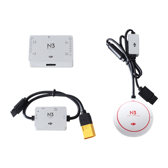
Page 6: N3-Ag Introduction
2. Support for multiple receiver types. If used with the DJI Datalink 3, the A3-AG has direct access to features in the DJI MG app such as intellignt planning and operation. 3. M1 to M8 are used to connect the ESCs of the aircraft and iESC for DJI Intelligent ESC communication. - Page 7 2. GNSS-Compass Status Indicator Indicates the status of the GNSS- Compass Module. 3. Extended CAN1 Port Dedicated DJI CAN-Bus port. Communicates with a DJI device. © 2017 DJI All Rights Reserved.
- Page 8 The LED Module has an integrated LED Indicator and Micro USB port. A. The LED is mainly for flight control system status indication during flight (e.g. Flight Mode). B. In addition, there is a Micro USB port for firmware upgrades via DJI Assistant 2. 1. Flight Status Indicator Indicates the status of the flight control system.
-
Page 9: Agriculture Management Unit (Amu) Introduction
Agriculture Management Unit (AMU) Introduction The Agriculture Management Unit (AMU) is equipped with essential expansion ports to support DJI modules such as Altitude Stabilization System, delivery pump, RTK. 12 13 4 5 6 1. 12V 2A 9. Pump Reserved power port, max operating Connected to the DJI integrated pump. -
Page 10: Installation
Installation Installation steps are similar for both the N3-AG and A3-AG. The descriptions in this chapter use the N3-AG as an example. Unless specified, the following context can also be applied to the A3- AG installation. Overview Installation Procedure Read this section carefully and follow the procedures below to install your flight control system, otherwise the flight control system may not normally work. - Page 11 DJI Assistant 2. DJI Datalink 3 DJI Datalink 3 lets you use DJI MG app to configure the flight control system parameters and utilize intelligent agricultural operation. DR16 The DR16 receiver does not support DJI MG app.
- Page 12 Mac App Store. 3. Locate the DJI Assistant 2 icon in the Finder, press the Control key and then click the DJI Assistant 2 icon (or right-click the DJI Assistant 2 icon using a mouse). Choose Open from the shortcut menu, click Open in the dialog box and the software will launch.
-
Page 13: Start The Installation
Make sure the module is parallel to the aircraft and then fix it onto the aircraft with double-faced adhesive tape. Configure the parameters in DJI Assistant 2 and select the direction in which you mounted the Flight Controller. We recommend mounting the Flight Controller with the Orientation Arrow pointing forward. - Page 14 GNSS-Compass bracket. Try to keep it parallel to the aircraft. Usage Requirements 1. The DJI logo should be facing the sky, with the orientation arrow pointing directly to the nose direction; otherwise you may experience take off failure. 2. Fly the aircraft in an open space without buildings or trees; otherwise the GPS satellite number may be affected.
- Page 15 LED module onto the aircraft. Mounting the PUM Module Mount the PMU module to an unobstructed position on the bottom of the aircraft’s upper plate for heat dissipation. © 2017 DJI All Rights Reserved.
- Page 16 Connecting to a Receiver Select the RF port or the S-Bus port for different types of receivers. DJI Datalink 3 Connect the DJI Datalink 3 receiver DBUS port to the Flight Controller RF Port with included RF Cable. RF Cable ©...
- Page 17 1. Connect the M1-M6 ports on the bottom board of the S900 to the M1-M6 ports on the Flight Controller in order. 2. The iESC port can connect to the DJI Smart ESC Communication Cable if using the DJI Intelligent ESC.
- Page 18 Connect to Expansion Devices Delivery Pump DJI delivery pump: used with the AMU. Mount the DJI delivery pump to the desired position, and then connect the power cable of the pump to the Pump port on the AMU. Other pumps: Connect the ESC signal cables of the pump to the F1 and F2 ports on the flight controller.
- Page 19 (30 seconds) of the data protection function. For the N3-AG: Connect the CAN cable of the module to the extended CAN1 port on the GNSS- Compass module. If using the AMU, connect it to the extended CAN1 port on the CAN-gimbal cable.
- Page 20 2 Connect the Micro USB port on the LED module to a PC via a Micro USB cable. 3 Run DJI Assistant 2. Note that you may be asked to register for first time use. 4 Follow the prompts to upgrade the firmware to the latest version*.
- Page 21 2 or 3 position Switch When using a 2 position switch, M+ function should be disabled in DJI Assistant 2, and then the two positions will be S and M. Spray Switch Channel 9 2 or 3 position To start or stop spraying.
- Page 22 A3-AG/N3-AG User Manual 2-position switch: P-mode and F-mode are by default. F-mode can be changed to A-mode in DJI Assistant 2. 4. Operation Mode Switch The flight controller features S, M and M+ operation modes (refer to System Functions for details).
-
Page 23: System Functions
GNSS signal is weak. If using the D-RTK*, it can provide centimeter-level positioning accuracy. If using Datalink 3, plan tasks in advance in the DJI MG app and the aircraft will automatically perform the selected task after entering F-mode with a strong GNSS signal. The DJI MG app will display “Route”. - Page 24 Manual Plus operation mode (M+): Users can control the movement of the aircraft, but flying speed is restricted and heading is locked. Use the C1 or C2 buttons on the remote controller to steer the aircraft left/right for one line spacing. If using the Datalink 3, the DJI MG app will display “M+ Route.”...
- Page 25 2. Configuring Aircraft Altitude If using the Altitude Stabilization System, configure the desired altitude in the DJI MG app and adjust the aircraft altitude to a value within the working range of the Altitude Stabilization System (2-3.5 m) by using the throttle stick before entering Smart operation mode.
- Page 26 Smart operation mode, when the aircraft regains a strong GNSS signal, it will automatically fly to the next turning point. The line spacing can be customized from 3-10 m in DJI Assistant 2. It is set to a length of 5 m by default.
- Page 27 Settings dial on the remote controller. The DJI MG app will display an icon of line spacing. Tap to adjust the value. The line spacing cannot be adjusted during operation. Switch to Manual or Manual Plus operation mode to adjust the value, then go back to Smart operation mode.
- Page 28 If you press the A or B buttons during operation, the data for Points A and B of the current route will be erased and the aircraft will hover in place. The line spacing can be customized from 3-10 m in DJI MG. It is set to a length of 5 m by default.
-
Page 29: Operation Resumption
Set the Operation Mode switch to M+ to enter Manual Plus operation mode. The aircraft's' Maximum flying speed is limited (customizable in DJI Assistant 2 or the DJI MG app), the heading is locked, and all other movement can be manually controlled in this mode. Press the C1 or C2 buttons on the remote controller to steer the aircraft left or right. - Page 30 If the aircraft is in the operating area, it will return to the operating route along a path vertical to the operating route. If the aircraft is out of the operating area, it will return straight to the breakpoint and resume operation. © 2017 DJI All Rights Reserved.
- Page 31 Smart operation mode — Set the Flight Mode switch to P and the Operation Mode switch to S. F-mode — Set the Flight Mode switch to F. Then Tap Resume on the lower right corner of the DJI MG app. 4. If obstacle avoidance is required during the return procedure, users can control the aircraft forwards, backwards, left, and right.
-
Page 32: Empty Tank Warning
(Manual operation mode or F-mode). * The feature for hovering at 3 m must be enabled in DJI Assistant 2 or the DJI MG app. If not enabled, the aircraft will hover in place at its current altitude and position until you manually control it. -
Page 33: Return To Home (Rth)
Smart RTH and regain control of the aircraft. Failsafe RTH Failsafe RTH must be enabled in the DJI Assistant 2 or DJI MG app. If Failsafe RTH is not enabled, the aircraft will hover in place when the remote controller signal is lost. - Page 34 The low battery RTH or critical low battery landing is triggered when the LiPo battery voltage is low. The Low Battery RTH is disabled by default. The Flight Status Indicator will blink red slowly when battery voltage is low. RTH or landing can be set in the DJI Assistant 2 or the DJI MG app.
-
Page 35: Attitude Control When One Motor Output Fails
1. During flight, the aircraft with this flight control system is attitude controllable when one motor output fails. 2. The motor will not start before take-off. (DJI Intelligent ESCs are required for communication.) Propulsion System Protection Low voltage and overweight aircraft warnings are provided. -
Page 36: Altitude Stabilization System
Stabilization System to maintain the same distance above the crops at all times. The radar module is enabled by default, and can be disabled in DJI Assistant 2. If it is enabled, the aircraft will fly above the crops at a constant spraying distance in Smart Operation Mode and Manual Plus Operation Mode. -
Page 37: Redundancy System
Blinks Once N3-AG with A3 Upgrade Kit With the A3 upgrade kit (IMU Pro and GPS-Compass Pro modules), the N3-AG Pro provides modular redundancy, improving the system’s anti-risk performance. System status is indicated by LEDs on the GNSS-Compass/GPS-Compass Pro, IMU Pro and Flight Controller modules. - Page 38 When the LED is blinking green. The module is functioning abnormally When the LED is blinking red. The module is functioning normally but not working as a part of the Blue system When the LED is blinking blue. © 2017 DJI All Rights Reserved.
-
Page 39: Flight
In A-mode, only the height limit prevents the aircraft from going above 50 meters. Maximum Height and Radius Limits Users can change the maximum height and radius limits in DJI Assistant 2 or the DJI MG app. Once complete, your aircraft will fly in a restricted cylinder that is determined by these settings. - Page 40 GNSS signal) afterwards, it will fly back within range automatically. No-Fly Zones Detailed no-fly zones are listed on the DJI official website at http://flysafe.dji.com/no-fly. No- fly zones are divided into airports and restricted areas. Airports include major airports and flying fields where manned aircraft operate at low altitudes.
-
Page 41: Pre-Flight Checklist
4. After successful calibration, the compass may become abnormal when you place the aircraft on the ground. This may be because of underground magnetic interference. Move the aircraft to another location and try again. © 2017 DJI All Rights Reserved. - Page 42 Flight Status Indicator blinks red, repeat the steps above to recalibrate the compass. Using DJI MG (Datalink 3 is required): Tap the Aircraft Status Bar in the Operation View of the DJI MG app and select Calibrate in the Aircraft Status List, then follow the on-screen instructions.
-
Page 43: Flight Control
Left Stick Right Stick You can customize or change these controls through the DJI MG app. Manual Landing Use the below method to stop the motors: When the aircraft has landed, push the throttle down and hold. The motors will stop after 3 seconds. -
Page 44: Dji Assistant 2
Configure settings of the remote controller and flying parameters, copy flight records, use the flight simulator, and update aircraft firmware in the DJI Assistant 2. Installation and Launching 1. Download the DJI Assistant 2 installation file from the MG-1S download page: http://www.dji.com/agriculture-solution/info#downloads 2. Install the software. - Page 45 (e.g., roll, pitch, yaw) will be shown on the right of the screen. Firmware Update A DJI account is required for firmware updates. Login with your DJI account or register for one. Flight Data You can use Data Viewer to view flight data, or enter SD card mode to copy it.
-
Page 46: Appendix
Multi modular redundancy (with the A3 upgrade kit) App Functions Intelligent Operation Planning (DJI MG App required) System DJI aerial platforms (e.g. S900, S1000, S1000+) Supported DJI Equipment DJI iOSD Mark II, DJI iOSD mini Peripheral 4-rotor: I4, X4 Supported Airframes... - Page 47 32° to 104° F (0° to 40° C) Altitude Stabilization System Detection Range 1.5 - 7 m (Varies when flying above different kinds of vegetation) Working Range 2 - 3.5 m Detection Accuracy < 10 cm © 2017 DJI All Rights Reserved.
-
Page 48: Flight Status Led Indicator Descriptions
Large IMU bias or IMU initialization second when performing CSC Critical error, refer to the 11th question under Solid Red FAQ chapter. Please contact with DJI Support —— if the problem is not solved. Blinking Red and Yellow Compass calibration required Alternatively ©... - Page 49 A3-AG/N3-AG User Manual Comparisons 1. What’s the difference between A3/N3 and A3-AG/N3-AG? The A3/N3 is used for aerial photography, while the A3-AG/N3-AG is used for agriculture. They use the same hardware basic. 2. What’s the biggest difference between A3-AG and N3-AG? The A3-AG supports RTK, while the N3-AG doesn’t.
- Page 50 9. How to copy the flight data? A data recorder is built-in the A3-AG/N3-AG. To copy the flight data, go to DJI Assistant 2 > Flight Data > Enter SD Card Mode. 10. In Dashboard page in the DJI Assistant 2, there are yellow exclamation points for IMU or GPS.
- Page 51 ESC abnormal Solutions: i. Go to DJI Assistant 2 > Basic Settings > ESC Settings to check if smart ESC is selected while a normal ESC is used (only Takyon Z14120 and E5000 is supported as a smart ESC).
- Page 52 The flight controller will reduce the gain value to land the aircraft, and the Flight Status Indicator will alert. Connect the flight controller to DJI Assistant 2 > Tools > Topology to view the error messages which will remind users to check the propulsion system.
- Page 53 DJI Support http://www.dji.com/support This content is subject to change. Download the latest version from http://www.dji.com/agriculture-solution If you have any questions about this document, please contact DJI by sending a message to DocSupport@dji.com. © Copyright 2017 DJI All Rights Reserved.
Need help?
Do you have a question about the N3-AG and is the answer not in the manual?
Questions and answers