Viking VGSO100 Service Manual
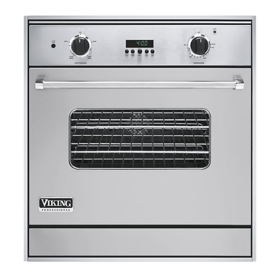
30” gas single wall oven
Hide thumbs
Also See for VGSO100:
- Installation manual (16 pages) ,
- Dimensions & specifications (4 pages) ,
- Quick reference manual (2 pages)
Table of Contents
Advertisement
Quick Links
Service
Preferred Service
Manual
This manual is to be used by qualified appliance technicians only.
Viking does not assume any responsibility for property damage
or personal injury for improper service procedures done by an
unqualified person.
30" Gas
This Base Manual covers general and
Single Wall Oven
specific information including, but not
limited to the following models:
VGSO100
SMC-0006
January 2009
Advertisement
Chapters
Table of Contents

Related Manuals for Viking VGSO100


Summary of Contents for Viking VGSO100
- Page 1 Service Preferred Service Manual This manual is to be used by qualified appliance technicians only. Viking does not assume any responsibility for property damage or personal injury for improper service procedures done by an unqualified person. 30” Gas This Base Manual covers general and Single Wall Oven specific information including, but not...
-
Page 2: Important Information
“DANGER”, “WARNING” or “CAUTION”. These words mean: CAUTION DANGER VIKING will not be responsible for any injury or property damage from improper service Immediate hazards which WILL result in severe procedures. If performing service on your personal injury or death. -
Page 3: Warranty Information
(12) months from the date of original retail purchase. Viking Range Corporation, warrantor, agrees to repair or replace, at its option, any part which fails or is found to be defective during the warranty period. -
Page 4: Warranty Service Information
The return of the Owner Registration Card is not a condition of warranty coverage. You should, however, return the Owner Registration Card so that Viking Range Corporation can contact you should any question of safety arise which could affect you. -
Page 5: Table Of Contents
High Limit Testing ...........20 Cooling Fan Limit Testing ........20 Convection Fan Motor Testing .......20 Control Testing ............21 Electronic Thermostat ..........21 Selector Switch ............22 DSI Module.............22 Test Procedures ............23 Bake/Broil Solenoids ..........24 Test Procedures ............24 Wiring Diagram ............25 © 2009 Viking Preferred Service... -
Page 6: General Information
2 ” 17-3/16” 18-5/8” (43.6 cm) (47.3 cm) 1/8”* 8 ” (.3 cm) - 7 / ( 6 3 1/2” 8 ” - 3 / Gas inlet (1.3 cm) ( 6 9 21-5/16” (54.1 cm) © 2009 Viking Preferred Service... -
Page 7: Warnings
The oven is designed specifically for natural gas or liquid propane (LP) gas. It is shipped from the factory adjusted for use with natural or propane (LP) gas. Before beginning installation verify that the model is compatible with the intended gas supply. © 2009 Viking Preferred Service... -
Page 8: Manual Shut-Off Valve
Removing the door must be done by your use a heavy-duty AGA design-certified flexible dealer, a qualified licensed plumber, or certified connector of at least 1/2” (1.3 cm) ID NPT (with gas installer. suitable strain reliefs) in compliance with ANSI Z21.41and Z21.69. © 2009 Viking Preferred Service... -
Page 9: Model - Serial Number Matrix
E=Electric S=Single D=Double O=Oven Serial Numbers 12 01 08 C0000000001 Month Serial Number Year of Manufacture The model and serial number tag is located on the inner frame to the lower left behind the door. © 2009 Viking Preferred Service... -
Page 10: Operation
BROIL (Infrared Broil) Convection Defrost (CONVECTION BAKE) Use this setting for broiling dark meats at 1” Use this function to defrost foods. thickness or less where rare or medium doneness is desired. © 2009 Viking Preferred Service... -
Page 11: Bake, Broil, Convect Bake, And Convect Broil
Use this setting for shrinkage. This even circulation of air equalizes broiling thick cuts of meats. the temperature throughout the oven cavity and eliminates the hot and cold spots found in conventional ovens. © 2009 Viking Preferred Service... -
Page 12: Service Diagnostics And Procedures
Broil Burner Broil Igniter Bake Burner Bake Igniter Convection Motor Assembly Oven Light Bulbs Oven Control Panel Clock Blower Motor High Temperature Cutout Door Hinge Receiver DSI Module Bake Solenoid Broil Solenoid Thermostat Selector Switch © 2009 Viking Preferred Service... -
Page 13: Parts Location - Control Panel
Parts Location – Control Panel OVEN BROIL BAKE OVEN LIGHT BROIL CONVECTION CONVECTION BROIL BAKE OVEN FUNCTION TEMPERATURE L1 115VAC Thermostat Neutral High Limit Thermostat Parts Location – Thermostat 245˚ F N.C. Selector Switch Main Control © 2009 Viking Preferred Service... -
Page 14: Parts Location - Rear Oven
Service Diagnostics and Procedures ® Parts Location – Rear Oven Power Cord Convection Motor 120VAC Broil Solenoid DSI Module Pressure Regulator Bake Solenoid © 2009 Viking Preferred Service... -
Page 15: Part Location - Main Oven
Service Diagnostics and Procedures ® Parts Location – Main Oven OVEN BROIL BAKE OVEN LIGHT BROIL CONVECTION CONVECTION BROIL BAKE OVEN FUNCTION TEMPERATURE Broil Burner Broil Igniter Bake Igniter Bake Burner Bake Igniter wire Service Plug © 2009 Viking Preferred Service... -
Page 16: Door Removal
Reinstall the hinge trim. Make sure to return the door pins to a safe place should the door need to be removed in the future. © 2009 Viking Preferred Service... -
Page 17: Component Testing Chart - Rtd Chart
Red to white at Motor motor Blower Motor 120 VAC White to black at blower High Limit 245 ˚F N.C. Blue to black at high limit Thermal Limit 160 ˚F Black to white at limit © 2009 Viking Preferred Service... -
Page 18: Component Troubleshooting Guide
Repair or replace defective wiring No lights Defective bulb Check for 120 VAC to the lights Oven light switch Verify light switch changes states when switch is pushed Defective or broken wiring Repair or replace defective wiring © 2009 Viking Preferred Service... -
Page 19: Rtd Temperature Sensor Testing
Note: When reinstalling the sensor, make sure the wire is pushed completely through insulation blanket. Failure to get the wires through the insulation blanket can overheat the wires resulting in defective wires. © 2009 Viking Preferred Service... -
Page 20: High Limit Testing
To access the limiter, remove the oven from installation. The main top will need to be removed and the limiter will be visible along the right hand side by the cooling fan. The limiter is normally open and closes at 160˚F. © 2009 Viking Preferred Service... -
Page 21: Control Testing
P7 red. Control should have 120 VAC from terminals L1 (double black wire) to L2/neutral (double white wire) and should supply 120 VAC to P7 black of thermostat. © 2009 Viking Preferred Service... -
Page 22: Selector Switch
Closed contacts CV to 3 supplies L1 power spark again. This process will continue until a flame to convection fan motor. is present. If the oven fails to ignite after three tries, © 2009 Viking Preferred Service... -
Page 23: Test Procedures
Brown 8 to 18 VDC Broil solenoid J1-4 White Neutral connection to DSI Module J1-6 Yellow 120 VAC from Selector BAKE J1-7 Red 120 VAC from Selector BROIL J1-10 Black Line Voltage to DSI module. © 2009 Viking Preferred Service... -
Page 24: Bake/Broil Solenoids
Test Procedures – Bake and Broil Solenoids Remove power to the unit. Set the Volt-Ohm meter to read resistance. Measure resistance at bake solenoid terminals. The Volt-Ohm meter should read 215 ohms +/- 30 ohms. © 2009 Viking Preferred Service... -
Page 25: Wiring Diagram
Wiring and Schematics ® © 2009 Viking Preferred Service...
Need help?
Do you have a question about the VGSO100 and is the answer not in the manual?
Questions and answers