Advertisement
Quick Links
Advertisement

Subscribe to Our Youtube Channel
Related Manuals for Olivetti d-color mf752plus


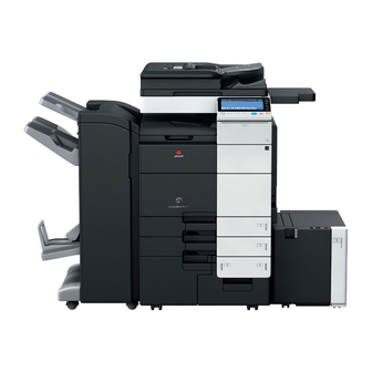
Summary of Contents for Olivetti d-color mf752plus
- Page 1 Multifuction Digital Copier d-Color MF752Plus, MF652Plus and Options SERVICE MANUAL Code: Y117760-6...
-
Page 2: Parts Layout Drawing
L PARTS/CONNECTOR LAYOUT DRAWING > 1. PARTS LAYOUT d-Color MF752Plus/MF652Plus DRAWING L PARTS/CONNECTOR LAYOUT DRAWING 1. PARTS LAYOUT DRAWING [12] [11] [10] Scanner motor (M201) Angle sensor (PS202) Original size sensor/2 (PS204) *1 CCD board (CCDB) Original cover sensor (RS201) - Page 3 L PARTS/CONNECTOR LAYOUT DRAWING > 1. PARTS LAYOUT d-Color MF752Plus/MF652Plus DRAWING [16] [17] [15] [14] [13] [12] [11] [10] IH power supply (IHPU) IH magnetic erasing board (IHMEB) Main power switch (SW1) Total counter (TCT) * Waste toner box set sensor (PS53)
- Page 4 L PARTS/CONNECTOR LAYOUT DRAWING > 1. PARTS LAYOUT d-Color MF752Plus/MF652Plus DRAWING [10] ERP board (ERPB) Printer control board (PRCB) Dual scan image processing board (DSIPB) Hard disk (HDD) DC power supply (DCPU) Paper feed/transport drive board (PFTDB) SSD board (SSDB)
- Page 5 L PARTS/CONNECTOR LAYOUT DRAWING > 1. PARTS LAYOUT d-Color MF752Plus/MF652Plus DRAWING High voltage unit/2 (HV2) High voltage unit/3 (HV3) High voltage unit/1 (HV1) Noise filter (NF1) Dehumidifier relay board (DEDB) Y117760-6 Service Manual...
- Page 6 L PARTS/CONNECTOR LAYOUT DRAWING > 1. PARTS LAYOUT d-Color MF752Plus/MF652Plus DRAWING [19] [17] [18] [16] [15] [14] [13] [12] [11] [10] Paper cooling fan/out (FM2) Transfer belt motor (M1) PC motor/K (M18) Ozone ventilation fan (FM6) Developing motor/K (M19) Charge cleaning motor/K (M15)
- Page 7 L PARTS/CONNECTOR LAYOUT DRAWING > 1. PARTS LAYOUT d-Color MF752Plus/MF652Plus DRAWING [10] [11] Fusing loop sensor/Rr (PS42) Fusing loop sensor/Fr (PS41) 1st transfer pressure sensor/K (PS51) Charging cleaner home sensor (PS43) Charging cleaner return sensor (PS44) Dehumidification heater switch (SW2)
- Page 8 L PARTS/CONNECTOR LAYOUT DRAWING > 1. PARTS LAYOUT d-Color MF752Plus/MF652Plus DRAWING PH relay board (PHRYB) [11] [10] Bypass lift-up motor (M28) Bypass paper feed motor (M27) Bypass sub tray set sensor (PS37) Bypass FD size sensor/3 (PS33) Bypass FD size sensor/2 (PS32)
- Page 9 L PARTS/CONNECTOR LAYOUT DRAWING > 1. PARTS LAYOUT d-Color MF752Plus/MF652Plus DRAWING [4] [5] [12] [11] [10] Tray 2 vertical transport motor (M7) Tray 2 paper feed clutch (CL2) Right bottom door sensor (PS17) Tray 2 upper limit sensor (PS14) Tray 2 vertical transport sensor (PS12)
- Page 10 L PARTS/CONNECTOR LAYOUT DRAWING > 1. PARTS LAYOUT d-Color MF752Plus/MF652Plus DRAWING [14] [15] [13] [12] [11] [10] Horizontal transport set sensor (PS58) Tray 4 paper feed clutch (CL7) Tray 4 upper limit sensor (PS27) Tray 4 paper empty sensor (PS24)
- Page 11 L PARTS/CONNECTOR LAYOUT DRAWING > 1. PARTS LAYOUT d-Color MF752Plus/MF652Plus DRAWING ADU paper passage sensor/1 (PS47) ADU paper passage sensor/2 (PS48) ADU transport motor/2 (M32) ADU door sensor (PS49) ADU transport motor/1 (M31) [14] [15] [13] [12] [11] [10] Switchback paper cooling fan (FM4)
- Page 12 L PARTS/CONNECTOR LAYOUT DRAWING > 1. PARTS LAYOUT d-Color MF752Plus/MF652Plus DRAWING DF control board (DFCB) CIS module (CIS) DF power supply (DFPU) [11] [10] Front side cleaning motor (M8) Reading roller pressure/retraction motor (M6) Stamp solenoid (SD1) * Lift-up motor (M5)
- Page 13 L PARTS/CONNECTOR LAYOUT DRAWING > 1. PARTS LAYOUT d-Color MF752Plus/MF652Plus DRAWING [23] [22] [21] [20] [19] [18] [17] [16] [15] [14] [13] [12] [10] [11] Length sensor/1 (PS10) Length sensor/3 (PS12) Length sensor/2 (PS11) Restriction plate positional volume (VR1) Lift up upper sensor (PS2)
- Page 14 L PARTS/CONNECTOR LAYOUT DRAWING > 1. PARTS LAYOUT d-Color MF752Plus/MF652Plus DRAWING Dehumidification heater (DH) Tray set sensor/2 (PS7) Paper feed sensor (PS3) Upper limit sensor (PS2) Tray set sensor/1 (PS1) [10] Lift-up motor (M1) [11] Paper feed motor (M2) [12]...
- Page 15 L PARTS/CONNECTOR LAYOUT DRAWING > 1. PARTS LAYOUT d-Color MF752Plus/MF652Plus DRAWING [15] [14] [13] [12] [11] [10] Main motor cooling fan (FM601) Punch shift motor (M605) Punch shift home sensor (PS605) ZU control board (ZUCB) Circuit breaker/2 (CBR2) Circuit breaker/1 (CBR1)
- Page 16 L PARTS/CONNECTOR LAYOUT DRAWING > 1. PARTS LAYOUT d-Color MF752Plus/MF652Plus DRAWING Punch motor (M604) Punch home sensor (PS606) Paper size detect board (PSDTB) Punch switchover switch (MS601) Punch switchover motor (M608) Punch clutch (CL601) [18] [19] [16] [17] [15] [14]...
- Page 17 L PARTS/CONNECTOR LAYOUT DRAWING > 1. PARTS LAYOUT d-Color MF752Plus/MF652Plus DRAWING [30] [31] [32] [29] [26] [27] [28] [25] [24] [23] [22] [21] [20] [19] [10] [18] [17] [12] [11] [14] [16] [13] [15] Shutter open/close switch (SW2) Leading edge paddle home sensor (PS16)
- Page 18 L PARTS/CONNECTOR LAYOUT DRAWING > 1. PARTS LAYOUT d-Color MF752Plus/MF652Plus DRAWING Punch drive motor (M301) PK punch hole position sensor/1 (PS307) PK punch scraps box set sensor (PS304) Punch control board (PKCB) PK punch hole scraps box full sensor (PS302)
- Page 19 L PARTS/CONNECTOR LAYOUT DRAWING > 1. PARTS LAYOUT d-Color MF752Plus/MF652Plus DRAWING [14] [13] [12] [10] [11] SD entrance sensor (PS1) Stacker paper sensor (PS3) Alignment home sensor (PS4) Paper receiving guide home sensor (PS2) Center fold change gate home sensor (PS11)
- Page 20 L PARTS/CONNECTOR LAYOUT DRAWING > 1. PARTS LAYOUT d-Color MF752Plus/MF652Plus DRAWING [1] [2] [3] [4] [23] [24] [22] [21] [20] [19] [10] [18] [13] [15] [17] [16] [14] [11] [12] PI drive board (PIDB) Transfer clutch /Lw (CL202) Registration clutch (CL203)
- Page 21 L PARTS/CONNECTOR LAYOUT DRAWING > 1. PARTS LAYOUT d-Color MF752Plus/MF652Plus DRAWING [31] [10] [30] [11] [12] [29] [28] [13] [14] [27] [32] [15] [26] [25] [16] [24] [17] [23] [22] [18] [21] [19] [20] Stacker motor sensor (PS25) Sub tray full detection sensor/out (PS9)
- Page 22 L PARTS/CONNECTOR LAYOUT DRAWING > 1. PARTS LAYOUT d-Color MF752Plus/MF652Plus DRAWING Punch dust full sensor/out (PS4) Punch dust full sensor/in (PS5) Punch motor sensor (PS3) Punch drive motor (M1) Punch position sensor (PS2) Punch home sensor (PS1) [10] Alignment motor (M3)
- Page 23 L PARTS/CONNECTOR LAYOUT DRAWING > 1. PARTS LAYOUT d-Color MF752Plus/MF652Plus DRAWING [13] [12] [11] [10] SD entrance sensor (PS1) Center staple/fold stacker paper detect sensor (PS3) Curl cover detection sensor (PS2) Alignment home sensor (PS4) Tri-folding gate home sensor (PS11)
-
Page 24: Connector Layout Drawing
L PARTS/CONNECTOR LAYOUT DRAWING > 2. CONNECTOR d-Color MF752Plus/MF652Plus LAYOUT DRAWING 2. CONNECTOR LAYOUT DRAWING Service Manual Y117760-6... - Page 25 L PARTS/CONNECTOR LAYOUT DRAWING > 2. CONNECTOR d-Color MF752Plus/MF652Plus LAYOUT DRAWING PJ15 (26pin) PJ01 (20pin) PJ27 (2pin) PJ23 PJ04 (8pin) (50pin) DIMM0 PJ21 PJ20 (88pin) (3pin) PJ22 DIMM1 PJ11 (7pin) PJ03 PJ05 (50pin) (N.C.) PJ12 (4pin) PJ07 (N.C.) PJ28 (3pin)
- Page 26 L PARTS/CONNECTOR LAYOUT DRAWING > 2. CONNECTOR d-Color MF752Plus/MF652Plus LAYOUT DRAWING n CN Service Manual Y117760-6...
- Page 27 L PARTS/CONNECTOR LAYOUT DRAWING > 2. CONNECTOR d-Color MF752Plus/MF652Plus LAYOUT DRAWING Y117760-6 Service Manual...
- Page 28 L PARTS/CONNECTOR LAYOUT DRAWING > 2. CONNECTOR d-Color MF752Plus/MF652Plus LAYOUT DRAWING Service Manual Y117760-6...
- Page 29 L PARTS/CONNECTOR LAYOUT DRAWING > 2. CONNECTOR d-Color MF752Plus/MF652Plus LAYOUT DRAWING 2 in Y117760-6 Service Manual...
- Page 30 L PARTS/CONNECTOR LAYOUT DRAWING > 2. CONNECTOR d-Color MF752Plus/MF652Plus LAYOUT DRAWING CN34 (6pin) CN35 (3pin) CN32 (8pin) CN33 (9pin) CN37 (6pin) CN36 (12pin) CN38 (11pin) CN301 CN300 (9pin) (3pin) Service Manual Y117760-6...
- Page 31 L PARTS/CONNECTOR LAYOUT DRAWING > 2. CONNECTOR d-Color MF752Plus/MF652Plus LAYOUT DRAWING CN2 (11pin) CN3 (6pin) CN10 (9pin) CN4 (19pin) CN9 (7pin) CN6 (4pin) CN11 (13pin) CN15 (12pin) CN8 (12pin) CN102 (40pin) CN5 (6pin) CN14 (6pin) CN1 (3pin) CN7 (4pin) CN11...
- Page 32 L PARTS/CONNECTOR LAYOUT DRAWING > 2. CONNECTOR d-Color MF752Plus/MF652Plus LAYOUT DRAWING (16pin) (10pin) (17pin) (3pin) (2pin) (24pin) (24pin) (32pin) (16pin) (8pin) (13pin) (10pin) (24pin) (2pin) (3pin) (6pin) (4pin) (4pin) (10pin) 2 in 2 in 1 1 1 (13pin) (4pin) (9pin)
- Page 33 L PARTS/CONNECTOR LAYOUT DRAWING > 2. CONNECTOR d-Color MF752Plus/MF652Plus LAYOUT DRAWING (13pin) (4pin) (9pin) (11pin) (13pin) (20pin) (6pin) (4pin) (4pin) (14pin) (10pin) 11 in Mark Meaning of mark Number of pin ○ Possible to confirm by removing external cover. The number in the mark represents the number of pin of the relay connector.
- Page 34 L PARTS/CONNECTOR LAYOUT DRAWING > 2. CONNECTOR d-Color MF752Plus/MF652Plus LAYOUT DRAWING [19] [18] [17] [16] [15] [14] [13] [12] [11] [10] Connector No. Location No. Connector No. Location No. CN321 CN174 CN180 10-R CN334 CN322 CN198 CN172 CN195<B> 11-S CN202...
- Page 35 L PARTS/CONNECTOR LAYOUT DRAWING > 2. CONNECTOR d-Color MF752Plus/MF652Plus LAYOUT DRAWING [27] [26] [25] [24] [23] [22] [21] [20] [19] [10] [18] [11] [17] [12] [15] [16] [14] [13] Connector No. Location No. Connector No. Location No. CN282 CN275 CN280...
- Page 36 L PARTS/CONNECTOR LAYOUT DRAWING > 2. CONNECTOR d-Color MF752Plus/MF652Plus LAYOUT DRAWING [16] [15] [14] [13] [12] [11] [10] Connector No. Location No. Connector No. Location No. CN297 22-E CN615 19-J CN511 20-D CN241 21-E CN165 10-J CN228 20-E CN702 CN378...
- Page 37 L PARTS/CONNECTOR LAYOUT DRAWING > 2. CONNECTOR d-Color MF752Plus/MF652Plus LAYOUT DRAWING [16] [15] [14] [13] [12] [11] [10] Connector No. Location No. Connector No. Location No. CN155<A> CN155<B> CN145 1 ~ 2-S CN279 CN613 19-I CN278 CN293 CN258 23 ~ 24-E...
Need help?
Do you have a question about the d-color mf752plus and is the answer not in the manual?
Questions and answers