Table of Contents
Advertisement
Quick Links
Advertisement
Table of Contents

Related Manuals for Cisco c240


Summary of Contents for Cisco c240
- Page 1 Cisco UCS C240 M4 Server Installation and Service Guide August 04, 2015 Cisco Systems, Inc. www.cisco.com Cisco has more than 200 offices worldwide. Addresses, phone numbers, and fax numbers are listed on the Cisco website at www.cisco.com/go/offices. Text Part Number: OL-32474-01...
- Page 2 Cisco and/or its affiliates in the United States and certain other countries. Cisco and the Cisco Logo are trademarks of Cisco Systems, Inc. and/or its affiliates in the U.S. and other countries. A listing of Cisco's trademarks can be found at www.cisco.com/go/trademarks.
-
Page 3: Table Of Contents
Connecting and Powering On the Server (Standalone Mode) 2-10 Local Connection Procedure 2-10 Remote Connection Procedure 2-11 Cisco IMC Configuration Utility Setup 2-12 NIC Modes and NIC Redundancy Settings 2-14 NIC Modes 2-14 NIC Redundancy 2-14 Cisco UCS C240 M4 Server Installation and Service Guide OL-32474-01... - Page 4 Replacing the Supercap Power Module (RAID Backup Battery) 3-34 Replacing a Software RAID 5 Key Module 3-36 Replacing the Motherboard RTC Battery 3-38 Replacing an Internal SD Card 3-39 Enabling or Disabling the Internal USB Port 3-40 Cisco UCS C240 M4 Server Installation and Service Guide OL-32474-01...
- Page 5 3-43 Replacing a PCIe Card 3-45 Special Considerations for Cisco UCS Virtual Interface Cards 3-47 Special Considerations for Cisco UCS Fusion ioDrive3 Storage Accelerator Cards 3-48 Installing Multiple PCIe Cards and Resolving Limited Resources 3-50 Installing an NVIDIA GPU Card...
- Page 6 A P P E N D I X Supported RAID Controllers and Required Cables Write-Cache Policy for Cisco 12G SAS Modular RAID Controller Support Matrix For Cisco UCS C240 M4 Server RAID Controllers Cisco UCS SAS 9300-8e HBA Considerations Mixing Rules...
- Page 7 Contents Installation for Cisco UCS Manager Integration A P P E N D I X Cisco UCS C240 M4 Server Installation and Service Guide OL-32474-01...
- Page 8 Contents Cisco UCS C240 M4 Server Installation and Service Guide viii OL-32474-01...
-
Page 9: Preface
Preface This preface describes the audience, organization, and conventions of the Cisco UCS C240 M4 Server Installation and Service Guide. It also provides information about how to obtain related documentation. Audience This guide is for experienced network administrators who configure and maintain Cisco servers. - Page 10 üblichen Verfahren zur Vorbeugung vor Unfällen vertraut. Suchen Sie mit der am Ende jeder Warnung angegebenen Anweisungsnummer nach der jeweiligen Übersetzung in den übersetzten Sicherheitshinweisen, die zusammen mit diesem Gerät ausgeliefert wurden. BEWAHREN SIE DIESE HINWEISE GUT AUF. Cisco UCS C240 M4 Server Installation and Service Guide OL-32474-01...
- Page 11 Använd det nummer som finns i slutet av varje varning för att hitta dess översättning i de översatta säkerhetsvarningar som medföljer denna anordning. SPARA DESSA ANVISNINGAR Cisco UCS C240 M4 Server Installation and Service Guide OL-32474-01...
- Page 12 Cisco UCS C240 M4 Server Installation and Service Guide OL-32474-01...
- Page 13 Brug erklæringsnummeret efter hver advarsel for at finde oversættelsen i de oversatte advarsler, der fulgte med denne enhed. GEM DISSE ANVISNINGER Cisco UCS C240 M4 Server Installation and Service Guide xiii OL-32474-01...
- Page 14 Cisco UCS C240 M4 Server Installation and Service Guide OL-32474-01...
-
Page 15: Related Documentation
Subscribe to What’s New in Cisco Product Documentation, which lists all new and revised Cisco technical documentation, as an RSS feed and deliver content directly to your desktop using a reader application. The RSS feeds are a free service. - Page 16 Cisco UCS C240 M4 Server Installation and Service Guide OL-32474-01...
-
Page 17: Chapter 1 Overview
C H A P T E R Overview This chapter provides an overview of the Cisco UCS C240 M4 server features: • External Features Overview, page 1-1 • Replaceable Component Locations, page 1-7 • Summary of Server Features, page 1-8 External Features Overview The figures in this chapter show an overview of external server features. - Page 18 SFF drives, 24-drive version of the server. This version of the server has a 24-drive backplane and an integrated expander. Figure 1-1 Cisco UCS C240 M4 Server (SFF Drives, 24-Drive) Front Panel Features Drive bays 1–24 (up to 24 2.5-inch drives) Temperature status LED...
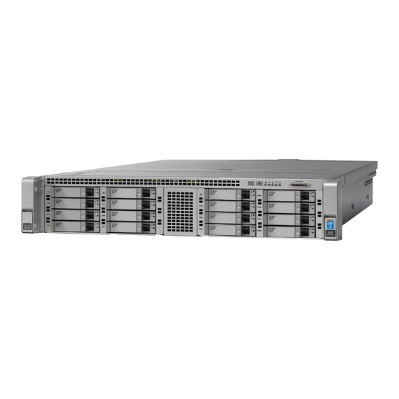
- Page 19 SFF drives, 16-drive version of the server. This version of the server has a 16-drive backplane and an integrated expander. Figure 1-2 Cisco UCS C240 M4 Server (SFF Drives, 16-Drive) Front Panel Features HDD01 HDD02...
- Page 20 SFF drives, 8-drive version of the server. This version of the server has a direct-connect, 8-drive backplane (no expander). Figure 1-3 Cisco UCS C240 M4 Server (SFF Drives, 8-Drive) Front Panel Features HDD01 HDD02...
- Page 21 LFF drives, 12-drive version of the server. This version of the server has a 12-drive backplane with an integrated expander. Figure 1-4 Cisco UCS C240 M4 Server (LFF Drives, 12-Drive) Front Panel Features HDD 01 HDD 02...
- Page 22 Power Specifications, page A-2 specifications and options. 10 Rear Unit Identification button/LED Modular LAN-on-motherboard (mLOM) card slot 11 Grounding-lug holes (for DC power supplies) USB 3.0 ports (two) 1-Gb dedicated management port Cisco UCS C240 M4 Server Installation and Service Guide OL-32474-01...
-
Page 23: Replaceable Component Locations
8 Trusted platform module (TPM) socket on 17 Supercap power module (RAID backup) motherboard, under PCIe riser 2 mounting location on air baffle (not shown) 9 PCIe riser 2 (PCIe slots 4, 5, 6) Cisco UCS C240 M4 Server Installation and Service Guide OL-32474-01... -
Page 24: Summary Of Server Features
Baseboard BMC, running Cisco Integrated Management Controller (Cisco IMC) firmware. management Depending on your Cisco IMC settings, Cisco IMC can be accessed through the 1-Gb dedicated management port, the 1-Gb Ethernet LOM ports, or a Cisco virtual interface card. Network and... - Page 25 This version holds up to 24 2.5-inch hard drives or solid state drives. Cisco UCS C240 M4—SFF drives with 16-drive backplane and integrated • expander. This version holds up to 16 2.5-inch hard drives or solid state drives.
- Page 26 Chapter 1 Overview Cisco UCS C240 M4 Server Installation and Service Guide 1-10 OL-32474-01...
- Page 27 Use the statement number provided at the end of each warning to locate its translation in the translated safety warnings that accompanied this device. Statement 1071 Cisco UCS C240 M4 Server Installation and Service Guide OL-32474-01...
-
Page 28: Chapter 2 Installing The Server
Invoice number of shipper (see the packing slip) • • Model and serial number of the damaged unit • Description of damage • Effect of damage on the installation Cisco UCS C240 M4 Server Installation and Service Guide OL-32474-01... -
Page 29: Preparing For Server Installation
Caution Avoid UPS types that use ferroresonant technology. These UPS types can become unstable with systems such as the Cisco UCS, which can have substantial current draw fluctuations from fluctuating data traffic patterns. Cisco UCS C240 M4 Server Installation and Service Guide... -
Page 30: Rack Requirements
This server supports one rail kit option: Cisco part UCSC-RAILB-M4= (ball-bearing rail kit). Do not attempt to use a rail kit that was for the Cisco UCS C240 M3 server; the rail kit for the Cisco UCS C240 M4 server has been designed specifically for it. -
Page 31: Installing The Server In A Rack
• Installing the Slide Rails This section describes how to install the server in a rack using the rack kits that are sold by Cisco. Warning To prevent bodily injury when mounting or servicing this unit in a rack, you must take special precautions to ensure that the system remains stable. - Page 32 Pull the inner slide rails on each assembly out toward the rack front until they hit the internal stops and lock in place. Cisco UCS C240 M4 Server Installation and Service Guide OL-32474-01...
- Page 33 The screw threads into the static part of the rail on the rack post and prevents the server from being pulled out. Repeat for the opposite slam latch. Cisco UCS C240 M4 Server Installation and Service Guide OL-32474-01...
-
Page 34: Installing The Cable Management Arm (Optional)
CMA tab on arm closest to the server and end Rear of server of inner slide rail attached to server Cisco UCS C240 M4 Server Installation and Service Guide OL-32474-01... -
Page 35: Reversing The Cable Management Arm (Optional)
180 degrees so that it points toward the rear of the server. Figure 2-5 Reversing the CMA CMA tab on end of width-adjustment slider Metal button for rotating Cisco UCS C240 M4 Server Installation and Service Guide OL-32474-01... -
Page 36: Initial Server Setup
Figure 1-4). This server node has a range of six MAC addresses assigned to the Cisco IMC. The MAC address printed on the label is the beginning of the range of six contiguous MAC addresses. Local Connection Procedure Step 1 Attach a power cord to each power supply in your server, and then attach each power cord to a grounded AC power outlet. -
Page 37: Remote Connection Procedure
Allow your preconfigured DHCP server to assign an IP address to the server node. Step 4 Use the assigned IP address to access and log in to the Cisco IMC for the server node. Consult with your DHCP server administrator to determine the IP address. -
Page 38: Cisco Imc Configuration Utility Setup
With this mode, the shared LOM and Cisco Card interfaces are both enabled. In this mode, DHCP replies are returned to both the shared LOM ports and the Cisco card ports. If the system determines that the Cisco card connection is not getting its IP address from a Cisco UCS Manager system because the server is in standalone mode, further DHCP requests from the Cisco card are disabled. - Page 39 Use a browser and the IP address of the Cisco IMC to connect to the Cisco IMC management interface. The IP address is based upon the settings that you made (either a static address or the address assigned by your DHCP server).
-
Page 40: Nic Modes And Nic Redundancy Settings
With this mode, the shared LOM and Cisco Card interfaces are both enabled. In this mode, DHCP replies are returned to both the shared LOM ports and the Cisco card ports. If the system determines that the Cisco card connection is not getting its IP address from a Cisco UCS Manager system because the server is in standalone mode, further DHCP requests from the Cisco card are disabled. -
Page 41: System Bios And Cisco Imc Firmware
When you upgrade the BIOS firmware, you must also upgrade Cisco IMC firmware to the same version Caution or the server will not boot. Do not power on the server until the BIOS and Cisco IMC firmware are matching or the server does not boot. -
Page 42: Accessing The System Bios
Follow the instructions on the Exit menu screen to save your changes and exit the setup utility (or Press Step 6 F10). You can exit without saving changes by pressing Esc. Cisco UCS C240 M4 Server Installation and Service Guide 2-16 OL-32474-01... -
Page 43: Chapter 3 Maintaining The Server
Server Monitoring and Management Tools Cisco Integrated Management Interface You can monitor the server inventory, health, and system event logs by using the built-in Cisco Integrated Management Controller (Cisco IMC) GUI or CLI interfaces. See the user documentation for your firmware release at the following URL: http://www.cisco.com/en/US/products/ps10739/products_installation_and_configuration_guides_list.html... -
Page 44: Status Leds And Buttons
Fan status LED Hard drive activity LED (on each drive tray) Temperature status LED Power button/power status LED Power supply status LED Unit Identification button/LED Network link activity LED System status LED Cisco UCS C240 M4 Server Installation and Service Guide OL-32474-01... - Page 45 Fan status • Green—All fan modules are operating properly. • Amber, steady—One or more fan modules breached the critical threshold. Amber, blinking—One or more fan modules breached the non-recoverable • threshold. Cisco UCS C240 M4 Server Installation and Service Guide OL-32474-01...
- Page 46 Off—The Ethernet link is idle. • Green—One or more Ethernet LOM ports are link-active, but there is no activity. • Green, blinking—One or more Ethernet LOM ports are link-active, with activity. Cisco UCS C240 M4 Server Installation and Service Guide OL-32474-01...
-
Page 47: Rear Panel Leds And Buttons
DC power supplies: Off—There is no DC power to the power supply. • Green, blinking—DC power OK; DC output not enabled. • Green, solid—DC power OK; DC outputs OK. • Cisco UCS C240 M4 Server Installation and Service Guide OL-32474-01... - Page 48 Green—Link is active. • Green, blinking—Traffic is present on the active link. • Unit Identification Off—The unit identification function is not in use. • Blue—The unit identification function is activated. • Cisco UCS C240 M4 Server Installation and Service Guide OL-32474-01...
- Page 49 Over-temperature protection (OTP) • • Solid on Blinking OTP warning • • • Solid on • Blinking OCP warning • Blinking • 12V main off (CR slave PSU is in sleep mode) Cisco UCS C240 M4 Server Installation and Service Guide OL-32474-01...
-
Page 50: Internal Diagnostic Leds
LED (under PCIe riser 1) Table 3-4 Internal Diagnostic LEDs, Definition of States LED Name State Internal diagnostic LEDs (all) Off—Component is functioning normally. • Amber—Component has a fault. • Cisco UCS C240 M4 Server Installation and Service Guide OL-32474-01... -
Page 51: Preparing For Server Component Installation
Emergency shutdown—Press and hold the Power button for 4 seconds to force the main power off and immediately enter standby mode. Step 3 Disconnect the power cords from the power supplies in your server to completely power off the server. Cisco UCS C240 M4 Server Installation and Service Guide OL-32474-01... -
Page 52: Removing And Replacing The Server Top Cover
Press the cover latch down to the closed position. The cover is pushed forward to the closed position as you push down the latch. If desired, lock the latch by using a screwdriver to turn the lock 90-degrees clockwise. Cisco UCS C240 M4 Server Installation and Service Guide 3-10 OL-32474-01... - Page 53 Chapter 3 Maintaining the Server Preparing for Server Component Installation Figure 3-4 Removing the Top Cover Front cover panel Locking cover latch Top cover Cisco UCS C240 M4 Server Installation and Service Guide 3-11 OL-32474-01...
-
Page 54: Serial Number Location
Hot-swap replacement—You do not have to precondition or shut down the component in the software before you remove it for the following components: – SAS/SATA drives – Cooling fan modules – Power supplies (when 1+1 redundant) Cisco UCS C240 M4 Server Installation and Service Guide 3-12 OL-32474-01... -
Page 55: Installing Or Replacing Server Components
Replacing Internal SATA Boot Drives, page 3-64 • Installing a Trusted Platform Module, page 3-66 • Replacing Power Supplies, page 3-69 • Replacing an mLOM Card, page 3-72 • Cisco UCS C240 M4 Server Installation and Service Guide 3-13 OL-32474-01... -
Page 56: Replaceable Component Locations
9 PCIe riser 2 (PCIe slots 4, 5, 6) The Technical Specifications Sheets for all versions of this server, which include supported component part numbers, are at Cisco UCS Servers Technical Specifications Sheets. Cisco UCS C240 M4 Server Installation and Service Guide 3-14 OL-32474-01... -
Page 57: Replacing Hard Drives Or Solid State Drives
The server is orderable in four different versions, each with one of four different front panel/backplane configurations: • Cisco UCS C240 M4—Small form-factor (SFF) drives with 24-drive backplane and expander. This version holds up to 24 2.5-inch hard drives or solid state drives. •... -
Page 58: Drive Replacement Procedure
With the ejector lever on the drive tray open, insert the drive tray into the empty drive bay. Push the tray into the slot until it touches the backplane, and then close the ejector lever to lock the drive in place. Cisco UCS C240 M4 Server Installation and Service Guide 3-16 OL-32474-01... - Page 59 Chapter 3 Maintaining the Server Installing or Replacing Server Components Figure 3-10 Replacing Drives Release button Drive tray securing screws (four) Ejector lever – Cisco UCS C240 M4 Server Installation and Service Guide 3-17 OL-32474-01...
-
Page 60: Replacing Fan Modules
Press down gently on the fan module until the latch clicks and locks in place. Step 6 Replace the top cover. Step 7 Replace the server in the rack. Cisco UCS C240 M4 Server Installation and Service Guide 3-18 OL-32474-01... - Page 61 Installing or Replacing Server Components Figure 3-12 Fan Modules Latch and Fault LED Riser 2 Riser 1 Finger latch (on each fan module) Fan module fault LED (on each fan module) Cisco UCS C240 M4 Server Installation and Service Guide 3-19 OL-32474-01...
-
Page 62: Replacing Dimms
DIMMs and their sockets are fragile and must be handled with care to avoid damage during installation. Caution Cisco does not support third-party DIMMs. Using non-Cisco DIMMs in the server might result in system problems or damage to the motherboard. -
Page 63: Front Of Server
NVIDIA GPUs can support only less than 1 TB of memory in the server. Therefore, do not install more than fourteen 64-GB DIMMs when using an NVIDIA GPU card in this server. • Observe the DIMM mixing rules shown in Table 3-5. Cisco UCS C240 M4 Server Installation and Service Guide 3-21 OL-32474-01... - Page 64 Furthermore, if memory mirroring is used, DRAM size is reduced by 50 percent for reasons of reliability. For details on populating recommended memory mirroring configurations, see the specification sheet for the server: Cisco UCS C240 M4 High Density Rack Server (Small Form-Factor Disk Drive Model) • Specification Sheet •...
-
Page 65: Dimm Replacement Procedure
Step 8 Replace the top cover. Step 9 Replace the server in the rack, replace cables, and then power on the server by pressing the Power button. Step 10 Cisco UCS C240 M4 Server Installation and Service Guide 3-23 OL-32474-01... -
Page 66: Replacing Cpus And Heatsinks
Use a Number 2 Phillips-head screwdriver to loosen the four captive screws that secure the heatsink. Alternate loosening each screw evenly to avoid damaging the heatsink or CPU. Note Cisco UCS C240 M4 Server Installation and Service Guide 3-24 OL-32474-01... - Page 67 Close the hinged CPU cover plate. Clip down the CPU retaining latch with the icon, and then clip down the CPU retaining latch with the icon. See Figure 3-14. Cisco UCS C240 M4 Server Installation and Service Guide 3-25 OL-32474-01...
- Page 68 Step 10 Step 11 Replace the top cover. Step 12 Replace the server in the rack, replace cables, and then power on the server by pressing the Power button. Cisco UCS C240 M4 Server Installation and Service Guide 3-26 OL-32474-01...
-
Page 69: Additional Cpu-Related Parts To Order With Rma Replacement Motherboards
Additional CPU-Related Parts to Order with RMA Replacement Motherboards When a return material authorization (RMA) of the motherboard or CPU is done on a Cisco UCS C-series server, additional parts might not be included with the CPU or motherboard spare bill of materials (BOM). -
Page 70: Replacing A Sata Interposer Board
Step 9 Replace the top cover. Step 10 Replace the server in the rack, replace cables, and then power on the server by pressing the Power button. Step 11 Cisco UCS C240 M4 Server Installation and Service Guide 3-28 OL-32474-01... - Page 71 Chapter 3 Maintaining the Server Installing or Replacing Server Components Figure 3-16 SATA Interposer Board Socket Location Riser 2 Riser 1 SATA interposer board socket on motherboard Cisco UCS C240 M4 Server Installation and Service Guide 3-29 OL-32474-01...
-
Page 72: Replacing A Cisco Modular Raid Controller Card
Chapter 3 Maintaining the Server Installing or Replacing Server Components Replacing a Cisco Modular RAID Controller Card The server has an internal, dedicated PCIe slot on the motherboard for a Cisco modular RAID controller card (see Figure 3-17). See also: Replacing a Modular RAID Controller Transportable Memory Module (TMM), page 3-32 •... - Page 73 Chapter 3 Maintaining the Server Installing or Replacing Server Components Figure 3-17 Modular RAID Controller Card Location Riser 2 Riser 1 Thumbscrews on card Cisco modular RAID controller bracket Cisco UCS C240 M4 Server Installation and Service Guide 3-31 OL-32474-01...
-
Page 74: Replacing A Modular Raid Controller Transportable Memory Module (Tmm)
Connect the cable from the supercap power module (RAID battery) to the connector on the TMM (see Figure 3-18). Align the two slots on the back of the RAID card bracket with the two pegs on the chassis wall. Cisco UCS C240 M4 Server Installation and Service Guide 3-32 OL-32474-01... - Page 75 Side view, socket on modular RAID card Guide pegs on bracket protruding through Side view, connector on underside of TMM guide holes on TMM SCPM cable connector on TMM Side view, securing clips Cisco UCS C240 M4 Server Installation and Service Guide 3-33 OL-32474-01...
-
Page 76: Replacing The Supercap Power Module (Raid Backup Battery)
Replace the top cover. Step 6 Replace the server in the rack, replace cables, and then power on the server by pressing the Power button. Step 7 Cisco UCS C240 M4 Server Installation and Service Guide 3-34 OL-32474-01... - Page 77 SCPM (RAID Backup Unit) Mounting Point and Cable Path Riser 2 Riser 1 SCPM mounting point on removable air baffle SCPM cable routing path (the red line) (air baffle not shown) Cisco UCS C240 M4 Server Installation and Service Guide 3-35 OL-32474-01...
-
Page 78: Replacing A Software Raid 5 Key Module
Hold the retention clips on the header open while you grasp the RAID key board and pull straight up (see Figure 3-21). Figure 3-20 RAID 5 Key Header Location on Motherboard Riser 2 Riser 1 Software RAID 5 key header (adds RAID 5 support) Cisco UCS C240 M4 Server Installation and Service Guide 3-36 OL-32474-01... - Page 79 Gently press down on the module until it is seated and the retention clip locks over the module (see Figure 3-21). Figure 3-21 Software RAID 5 Key Module Retention Clip Printed circuit board on module Motherboard header Retention clip on motherboard header Retention clip in installed position Cisco UCS C240 M4 Server Installation and Service Guide 3-37 OL-32474-01...
-
Page 80: Replacing The Motherboard Rtc Battery
The positive side of the battery marked “3V+” should face upward. Step 6 Replace the top cover. Step 7 Replace the server in the rack, replace cables, and power on the server by pressing the Power button. Cisco UCS C240 M4 Server Installation and Service Guide 3-38 OL-32474-01... -
Page 81: Replacing An Internal Sd Card
Replacing an Internal SD Card The server has two internal SD card bays on the motherboard. Dual SD cards are supported. RAID 1 support can be configured through the Cisco IMC interface. Step 1 Power off the server as described in Shutting Down and Powering Off the Server, page 3-9. -
Page 82: Enabling Or Disabling The Internal Usb Port
Step 5 Scroll to USB Port: Internal, press Enter, and then choose either Enabled or Disabled from the dialog box. Step 6 Press F10 to save and exit the utility. Cisco UCS C240 M4 Server Installation and Service Guide 3-40 OL-32474-01... -
Page 83: Replacing A Pcie Riser
Replace the top cover. Step 6 Replace the server in the rack, replace cables, and then power on the server by pressing the Power button. Step 7 Cisco UCS C240 M4 Server Installation and Service Guide 3-41 OL-32474-01... - Page 84 Installing or Replacing Server Components Figure 3-24 PCIe Riser Alignment Features Riser 2 Riser 1 Alignment peg locations on motherboard Alignment channel locations on chassis (two for each riser) (two for each riser) Cisco UCS C240 M4 Server Installation and Service Guide 3-42 OL-32474-01...
-
Page 85: Replacing A Pcie Card
Replacing a PCIe Card Caution Cisco supports all PCIe cards qualified and sold by Cisco. PCIe cards not qualified or sold by Cisco are the responsibility of the customer. Although Cisco will always stand behind and support the C-Series rack-mount servers, customers using standard, off-the-shelf, third-party cards must go to the third-party card vendor for support if any issue with that particular third-party card occurs. - Page 86 1. NCSI is supported in only one slot at a time in this riser version. If a GPU card is present in slot 5, NCSI support automatically moves to slot 4. Cisco UCS C240 M4 Server Installation and Service Guide...
-
Page 87: Replacing A Pcie Card
Cisco UCS Servers Technical Specifications Sheets. Note If you are installing a Cisco UCS Virtual Interface Card, there are prerequisite considerations. See Special Considerations for Cisco UCS Virtual Interface Cards, page 3-47. If you are installing a Fusion ioDrive2 card, there are prerequisite considerations. See... - Page 88 PCIe Riser Securing Features (Three-Slot Riser Shown) Securing plate hinge-tabs GPU card power connector Securing plate thumbscrew (knob not visible Card-tab retainer in open position on underside of plate) Cisco UCS C240 M4 Server Installation and Service Guide 3-46 OL-32474-01...
-
Page 89: Special Considerations For Cisco Ucs Virtual Interface Cards
PCIe slot for integration, but if an mLOM-style card is present it takes priority over the PCIe slot for integration. 4. For Cisco UCS VIC1385, always use the primary slots 2 and 5 for optimal performance. You can use the other supported slots, but you might see degraded performance. -
Page 90: Special Considerations For Cisco Ucs Fusion Iodrive3 Storage Accelerator Cards
Installing or Replacing Server Components Special Considerations for Cisco UCS Fusion ioDrive3 Storage Accelerator Cards Table 3-11 describes the requirements for the supported Cisco UCS Fusion ioDrive3 cards. Table 3-11 Cisco UCS C240 M4 Requirements for Fusion ioDrive2 Cards Slots That Slots That Support >25W... - Page 91 For example: options iomemory-vsl external_power_override=1149D0969,1159E0972 Step 3 Reboot the server or unload and then load the drivers to enforce the parameter changes. Cisco UCS C240 M4 Server Installation and Service Guide 3-49 OL-32474-01...
-
Page 92: Installing Multiple Pcie Cards And Resolving Limited Resources
If the system BIOS does not have sufficient memory space to load any PCIe option ROM, it skips loading that option ROM, reports a system event log (SEL) event to the Cisco IMC controller and reports the following error in the Error Manager page of the BIOS Setup utility:... - Page 93 VICs that are not required for the system boot configuration by using the Network Adapters page in Cisco IMC Web UI to free up some 16-bit I/O resources. Each VIC uses a minimum 16 KB of 16-bit I/O resource, so disabling PXE boot on Cisco VICs would free up some 16-bit I/O resources that can be used for other PCIe cards that are installed in the system.
-
Page 94: Installing An Nvidia Gpu Card
GPU cards are also supported in PCIe riser 2, slot 5. Caution Cisco C240 M4 LFF and C240 M4 SFF 24-drive servers only: When using NVIDIA GPU cards, you must preserve at least 10 mm of space between servers to ensure adequate air flow. When using GPU cards with this version of the server, the operating temperature range is 32°... - Page 95 Cisco UCS Manager Controlled Server If the server is integrated with Cisco UCS Manager and controlled by a service profile, this setting is not enabled by default in the service profile. You must enable it with a BIOS policy in your service profile.
- Page 96 Tighten the single thumbscrew that holds the securing plate. Close the card-tab retainer (see Figure 3-26). Position the PCIe riser over its socket on the motherboard and over its alignment features in the chassis (see Figure 3-24). Cisco UCS C240 M4 Server Installation and Service Guide 3-54 OL-32474-01...
- Page 97 Replace the server in the rack, replace cables, and then power on the server by pressing the Power button. Step 8 Continue with Installing Drivers to Support the NVIDIA GPU Cards, page 3-63. Cisco UCS C240 M4 Server Installation and Service Guide 3-55 OL-32474-01...
- Page 98 Installing or Replacing Server Components Installing an NVIDIA K80 GPU Card and Conversion Kit The NVIDIA K80 GPU card requires a special conversion kit for the Cisco UCS C240 M4 server. NVIDIA K80 GPU Card Conversion Kit The contents of the conversion kit are as follows: •...
- Page 99 Install the low-profile replacement heatsinks that come with the conversion kit: Step 11 Remove the protective tape from the pre-applied pad of thermal grease that is on the underside of the new heatsink. Cisco UCS C240 M4 Server Installation and Service Guide 3-57 OL-32474-01...
- Page 100 Set the three holes in the GPU card front support bracket over the three screw holes. Insert and tighten the three thumbscrews into the three screw holes to secure the front bracket to the GPU card. Cisco UCS C240 M4 Server Installation and Service Guide 3-58 OL-32474-01...
- Page 101 The white connector on the cable connects to the GPU POWER connector on the riser; the black connector on the cable connects to the GPU card. Close the card-tab retainer (see Figure 3-26). Cisco UCS C240 M4 Server Installation and Service Guide 3-59 OL-32474-01...
- Page 102 Figure 3-30 GPU Front Support Bracket Inserted to Air Baffle Latch Front end of GPU Lip on support bracket latch Front support bracket attached to GPU Latch release tab Cisco UCS C240 M4 Server Installation and Service Guide 3-60 OL-32474-01...
- Page 103 Set the module into the clips and gently press down until the clip closes over the module. Route the module’s cable through the opening in the air baffle (see Figure 3-31) so that it does not interfere with the server top cover. Cisco UCS C240 M4 Server Installation and Service Guide 3-61 OL-32474-01...
- Page 104 Replace the server in the rack, replace cables, and then power on the server by pressing the Power button. Step 22 Continue with Installing Drivers to Support the NVIDIA GPU Cards, page 3-63. Step 23 Cisco UCS C240 M4 Server Installation and Service Guide 3-62 OL-32474-01...
- Page 105 2. Updating the NVIDIA Drivers, page 3-63 • 1. Updating the C240 M4 Server BIOS Install the latest Cisco UCS C240 M4 server BIOS by using the Host Upgrade Utility for the Cisco UCS C240 M4 server. Note You must do this procedure before you update the NVIDIA drivers.
-
Page 106: Replacing Internal Sata Boot Drives
Tighten the single thumbscrew that holds the securing plate. Position the PCIe riser over its socket on the motherboard and over its alignment features in the chassis (see Figure 3-24). Cisco UCS C240 M4 Server Installation and Service Guide 3-64 OL-32474-01... - Page 107 Boot the server and press F2 when prompted to enter the BIOS Setup Utility. Select the Boot Options tab. Set the boot order for your SATA boot drives. Press F10 to exit the utility and save your changes. Cisco UCS C240 M4 Server Installation and Service Guide 3-65 OL-32474-01...
-
Page 108: Installing A Trusted Platform Module
Replace the server in the rack, replace cables, and then power on the server by pressing the Power button. Step 10 Continue with Enabling TPM Support in the BIOS, page 3-67. Cisco UCS C240 M4 Server Installation and Service Guide 3-66 OL-32474-01... -
Page 109: Enabling Tpm Support In The Bios
Choose Trusted Computing to open the TPM Security Device Configuration window. Verify that TPM SUPPORT and TPM State are Enabled. Continue with Enabling the Intel TXT Feature in the BIOS, page 3-68. Step 3 Cisco UCS C240 M4 Server Installation and Service Guide 3-67 OL-32474-01... -
Page 110: Enabling The Intel Txt Feature In The Bios
Return to the Intel TXT(LT-SX) Hardware Support window if you are not already there. Set TXT Support to Enabled. Press F10 to save your changes and exit the BIOS Setup utility. Step 5 Cisco UCS C240 M4 Server Installation and Service Guide 3-68 OL-32474-01... -
Page 111: Replacing Power Supplies
Note power off the server to replace power supplies because they are redundant as 1+1 and hot-swappable. Do not mix power supply types in the server. Both power supplies must be the same wattage and Cisco Note product ID (PID). -
Page 112: Wiring A Dc Power Supply
Be sure uninsulated conductors are not accessible when cover is in place. Statement 1075 Note The recommended wire gauge is 8 AWG. The minimum wire gauge is 10 AWG. Cisco UCS C240 M4 Server Installation and Service Guide 3-70 OL-32474-01... - Page 113 Step 8 with the power supply label “+ DC”. Figure 3-34 930 W, –48 VDC Power Supply Connector Block Wire retainer lever Orange plastic button on top of the connector Cisco UCS C240 M4 Server Installation and Service Guide 3-71 OL-32474-01...
-
Page 114: Replacing An Mlom Card
Step 7 Replace the top cover. Step 8 Replace the server in the rack, replace cables, and then power on the server by pressing the Power button. Step 9 Cisco UCS C240 M4 Server Installation and Service Guide 3-72 OL-32474-01... - Page 115 Chapter 3 Maintaining the Server Installing or Replacing Server Components Figure 3-35 mLOM Card Location Riser 2 Riser 1 mLOM card socket location on motherboard (under PCIe riser 1) Cisco UCS C240 M4 Server Installation and Service Guide 3-73 OL-32474-01...
-
Page 116: Service Dip Switches
• Clear CMOS—switch 4. Figure 3-36 Service DIP Switches Riser 2 Riser 1 DIP switch block SW8 Clear password switch 2 Clear CMOS switch 4 BIOS recovery switch 1 Cisco UCS C240 M4 Server Installation and Service Guide 3-74 OL-32474-01... -
Page 117: Using The Bios Recovery Dip Switch
Step 6 Wait for server to complete the BIOS update, and then remove the USB thumb drive from the server. During the BIOS update, Cisco IMC shuts down the server and the screen goes blank for about Note 10 minutes. Do not unplug the power cords during this update. Cisco IMC powers on the server after the update is complete. -
Page 118: Procedure 2: Use Bios Recovery Dip Switch And Recovery.cap File
Wait for server to complete the BIOS update, and then remove the USB thumb drive from the server. Note During the BIOS update, Cisco IMC shuts down the server and the screen goes blank for about 10 minutes. Do not unplug the power cords during this update. Cisco IMC powers on the server after the update is complete. -
Page 119: Using The Clear Password Dip Switch
Step 11 Replace the top cover, replace the server in the rack, replace power cords and any other cables, and then power on the server by pressing the Power button. Cisco UCS C240 M4 Server Installation and Service Guide 3-77 OL-32474-01... -
Page 120: Using The Clear Cmos Dip Switch
Step 11 Replace the top cover, replace the server in the rack, replace power cords and any other cables, and then power on the server by pressing the Power button. Cisco UCS C240 M4 Server Installation and Service Guide 3-78 OL-32474-01... -
Page 121: Appendix
31.5 in. (80.00 cm) handles Maximum Weight (fully loaded) SFF 8-drive: 52.9 lb. (24.0 Kg) SFF 16-drive: 58.9 lb. (26.7 Kg) SFF 24-drive: 62.7 lb. (28.4 Kg) LFF 12-drive: 67.5 lb. (30.6 Kg) Cisco UCS C240 M4 Server Installation and Service Guide OL-32474-01... -
Page 122: Power Specifications
1400 W AC Power Supply, page A-3 • • 930 W DC Power Supply, page A-4 You can get more specific power information for your exact server configuration by using the Cisco UCS Power Calculator: http://ucspowercalc.cisco.com 650 W AC Power Supply... - Page 123 Maximum input volt-amperes 1700 VA Maximum output power per PSU 1400 W at 200–240 VAC Maximum inrush current 35 A (sub-cycle duration) Maximum hold-up time 12 ms at 1200 W Cisco UCS C240 M4 Server Installation and Service Guide OL-32474-01...
-
Page 124: W Dc Power Supply
8 ms at 930 W Power supply output voltage 12 VDC Power supply standby voltage 12 VDC Efficiency rating > 92% at 50% load Form factor RSP1 Input connector Removable connector block UCSC-CONN-930WDC= Cisco UCS C240 M4 Server Installation and Service Guide OL-32474-01... -
Page 125: Environmental Specifications
(when the server is in storage or is transported) Sound power level Measure A-weighted per ISO7779 LwAd (Bels) Operation at 73°F (23°C) Sound pressure level Measure A-weighted per ISO7779 LpAm (dBA) Operation at 73°F (23°C) Cisco UCS C240 M4 Server Installation and Service Guide OL-32474-01... -
Page 126: Environmental Specifications
Appendix A Server Specifications Environmental Specifications Cisco UCS C240 M4 Server Installation and Service Guide OL-32474-01... -
Page 127: Appendix
Power Cord, 250 VAC 10 A M 2511 Plug Europe SFS-250V-10A-ID Figure B-5 Power Cord, 250 VAC 16A EL-208 Plug South Africa, United Arab Emirates, India SFS-250V-10A-IS Figure B-6 Power Cord, 250 VAC 10 A SI32 Plug Israel Cisco UCS C240 M4 Server Installation and Service Guide OL-32474-01... - Page 128 Cabinet Jumper Power Cord, 250 VAC 10 A, C13-C14 Connectors CAB-C13-C14-2M Figure B-14 Cabinet Jumper Power Cord, 250 VAC 10 A, C13-C14 Connectors CAB-C13-C14-AC Figure B-15 Cabinet Jumper Power Cord, 250 VAC 10 A, C13-C14 Connectors Cisco UCS C240 M4 Server Installation and Service Guide OL-32474-01...
-
Page 129: Appendix B Power Cord Specification
Length: 2500mm Connector: Plug: EL 701C EL 206 (IEC 60320/C15) A.S. 3112-2000) Figure B-3 SFS-250V-10A-CN Cordset rating 10A, 250V Plug: (2500 mm) EL 218 (CCEE GB2009) Connector: EL 701 (IEC60320/C13) Cisco UCS C240 M4 Server Installation and Service Guide OL-32474-01... - Page 130 SFS-250V-10A-ID Cordset rating 16A, 250V Plug: (2500mm) EL 208 Connector: EL 701 Figure B-6 SFS-250V-10A-IS Cordset rating 10A, 250V/500V MAX (2500 mm) Connector: EL 701B Plug: (IEC60320/C13) EL 212 (SI-32) Cisco UCS C240 M4 Server Installation and Service Guide OL-32474-01...
- Page 131 Connector: IEC 60320 C15 Figure B-9 CAB-9K10A-UK Cordset rating: 10 A, 250 V/500 V MAX Length: 2500mm Connector: EL 701C Plug: EL 210 (EN 60320/C15) (BS 1363A) 13 AMP fuse Cisco UCS C240 M4 Server Installation and Service Guide OL-32474-01...
- Page 132 CAB-N5K6A-NA Cordset rating: 10 A, 250 V Length: 8.2 ft Plug: NEMA 6-15P Connector: IEC60320/C13 Figure B-12 CAB-9K12A-NA Cordset rating 13A, 125V (8.2 feet) (2.5m) Plug: Connector: IEC60320/C15 NEMA 5-15P Cisco UCS C240 M4 Server Installation and Service Guide OL-32474-01...
- Page 133 CAB-C13-C14-2M, Jumper Power Cord (2 m) Cordset rating 10A, 250V (2.0 m) Connector: Plug: HS10S SS10A Figure B-15 CAB-C13-C14-AC, Jumper Power Cord (3 m) Cordset rating 10A, 250V (3.0 m) Connector: Plug: HS10S SS10A Cisco UCS C240 M4 Server Installation and Service Guide OL-32474-01...
-
Page 134: Power Cord Specifications
Appendix B Power Cord Specifications Supported Power Cords and Plugs Cisco UCS C240 M4 Server Installation and Service Guide OL-32474-01... -
Page 135: Appendix
Supported RAID Controllers and Required Cables, page C-2 • Write-Cache Policy for Cisco 12G SAS Modular RAID Controller, page C-3 • Support Matrix For Cisco UCS C240 M4 Server RAID Controllers, page C-4 • Cisco UCS SAS 9300-8e HBA Considerations, page C-4 •... -
Page 136: Supported Raid Controllers And Required Cables
(SFF 24-drive and LFF 12-drive server versions only) while you use a hardware RAID controller card to control the front-facing drives. Note Support Matrix For Cisco UCS C240 M4 Server RAID Controllers, page C-4 for information about controller support by server version and drive type. -
Page 137: Write-Cache Policy For Cisco 12G Sas Modular Raid Controller
Modular RAID controller is Write Through (irrespective of the presence of a charged Supercap power module or “good BBU”). This utilizes the optimal performance characteristics of the controller. If you have Cisco IMC 2.0(5) or later firmware installed to the M4 server, the write policy can be set to Write Back, if preferred. -
Page 138: Support Matrix For Cisco Ucs C240 M4 Server Raid Controllers
Setting the Preferred Boot Device for Cisco UCS 9300-8e, page C-5 Mixing Rules Do not mix the Cisco UCS 9300-8e HBA in the same server as the Cisco UCS 12G SAS Modular HBA. Cisco UCS 9300-8e Bad Drive and Predictive Failure Behavior The bad drive and predictive failure behavior for the Cisco UCS SAS 9300-e HBA cards is different than that for LSI MegaRAID cards. -
Page 139: Setting The Preferred Boot Device For Cisco Ucs 9300-8E
The preferred device that you selected in the LSI BIOS CU is listed at the top of the list. Step 6 Select the device at the top of the list as your boot option. Cisco UCS C240 M4 Server Installation and Service Guide OL-32474-01... -
Page 140: Mixing Drive Types In Raid Groups
The SCPM provides approximately three years of backup for the disk write-back cache DRAM in the case of a sudden power loss by offloading the cache to the NAND flash. For SCPM replacement instructions, see Replacing the Supercap Power Module (RAID Backup Battery), page 3-34. Cisco UCS C240 M4 Server Installation and Service Guide OL-32474-01... -
Page 141: Raid Controller Cabling
C-1. • The red line shows the recommended cable routing path from the Cisco modular RAID controller card or the embedded SATA RAID interposer board to the drive backplane or expander. Cable clips on the chassis wall secure the cables. -
Page 142: Cisco Ucs C240 M4 Server Raid Controller Cabling Instructions
Appendix C RAID Controller Considerations RAID Controller Cabling Cisco UCS C240 M4 Server RAID Controller Cabling Instructions This section contains cabling instructions for controlling front-facing drives in the four server versions and their supported cables: SFF 8-Drive Direct-Connect Backplane, No Expander, page C-8 •... -
Page 143: Sff 24-Drive Backplane With Expander Cabling
Y-cable with a mini-SAS HD double connector on one 240CBLHBA12= end and two mini-SAS HD single connectors on the other end. Make the following connections: Connect the mini-SAS double connector to the modular RAID controller card. Cisco UCS C240 M4 Server Installation and Service Guide OL-32474-01... - Page 144 RAID Controller Cabling Connect single connector PORT A to the PORT A connector on the backplane. Connect single connector PORT B to the PORT B connector on the backplane. Cisco UCS C240 M4 Server Installation and Service Guide C-10 OL-32474-01...
-
Page 145: Embedded Sata Raid Controller
LFF 12-drive or the SFF 24-drive version of the server. Only the LFF 12-drive and the SFF 24-drive versions of the server support internal boot SSDs. No cabling is required for managing the internal SSD boot drives. Cisco UCS C240 M4 Server Installation and Service Guide C-11 OL-32474-01... -
Page 146: Embedded Sata Raid: Two Sata Controllers
Embedded SATA RAID: Two SATA Controllers The embedded RAID Patsburgh controller hub (PCH) is split into two controllers: SATA and sSATA (secondary SATA). These two controllers are seen as separate RAID controllers in the Cisco IMC interface and are configurable separately. -
Page 147: Embedded Sata Raid Controller Considerations
This chip upgrades support to add embedded SATA RAID 5 support for front-facing drive control. To install a RAID 5 key module, see Replacing a Software RAID 5 Key Module, page 3-36. Cisco UCS C240 M4 Server Installation and Service Guide C-13 OL-32474-01... -
Page 148: Enabling The Embedded Raid Controller In The Bios
LSI SW RAID—In supported server versions, you can manage the internal SSD boot drives or the front-facing drives by using the server’s embedded SATA RAID controller. For support by server version, see Support Matrix For Cisco UCS C240 M4 Server RAID Controllers, page C-4. - Page 149 Appendix C RAID Controller Considerations Embedded SATA RAID Controller Press F10 to save your changes and exit the utility. Step 3 Cisco UCS C240 M4 Server Installation and Service Guide C-15 OL-32474-01...
-
Page 150: Disabling The Embedded Raid Controller In The Bios
Enabling SATA Mode and Selecting Option ROM Mode, page C-14. For information about using the Embedded MegaRAID software to configure your disk arrays, see the LSI Embedded MegaRAID Software User Guide. Cisco UCS C240 M4 Server Installation and Service Guide C-16 OL-32474-01... -
Page 151: Installing Lsi Megasr Drivers For Windows And Linux
See the following URL: http://www.cisco.com/cisco/software/navigator.html Click Unified Computing and Servers in the middle column. Click Cisco UCS C-Series Rack-Mount Standalone Server Software in the right-hand column. Click your model of server in the right-hand column. Click Unified Computing System (UCS) Drivers. - Page 152 Windows installation disk into the drive. Skip to Step • To install from remote ISO, log in to the server’s Cisco IMC interface and continue with the next step. Launch a Virtual KVM console window and click the Virtual Media tab.
- Page 153 Properties. On the Driver tab, click Update Driver to open the Update Device Driver wizard, and then follow the Step 4 wizard instructions to update the driver. Cisco UCS C240 M4 Server Installation and Service Guide C-19 OL-32474-01...
- Page 154 MegaRAID stack. Note The LSI MegaSR drivers that Cisco provides for Red Hat Linux and SUSE Linux are for the original GA versions of those distributions. The drivers do not support updates to those OS kernels. Preparing Physical Installation Disks For Linux This section describes how to prepare physical Linux installation disks from the driver image files, using either the Windows operating system or the Linux operating system.
- Page 155 Under Red Hat Linux and SUSE Linux, you can use a driver disk utility to create disk images from image files. The driver image is too large for a floppy disk, so use a USB thumb drive instead. Note Download the Cisco UCS C-Series drivers ISO, as described in Downloading the LSI MegaSR Drivers, Step 1 page C-17 and save it to your Linux system that has a disk drive.
- Page 156 RHEL installation disk into the drive. Then continue with Step To install from remote ISO, log in to the server’s Cisco IMC interface. Then continue with the next • step. Launch a Virtual KVM console window and click the Virtual Media tab.
- Page 157 Then return to Step 4 of this procedure. • To install from a virtual floppy disk, download and save the Cisco UCS C-Series drivers’ ISO, as described in Downloading the LSI MegaSR Drivers, page C-17. Then continue with the next step.
- Page 158 • first RHEL install disc into the drive. Skip to Step To install from remote ISO, log in to the server’s Cisco IMC interface and continue with the next • step. Launch a Virtual KVM console window and click the Virtual Media tab.
-
Page 159: Restoring Raid Configuration After Replacing A Raid Controller
F quickly enough when prompted. In this case, reboot the server and try the import operation again when you are prompted to press F. 0 Virtual Drive(s) found on host adapter. Cisco UCS C240 M4 Server Installation and Service Guide C-25 OL-32474-01... -
Page 160: For More Information
Full Avago Technologies/LSI documentation is also available: For hardware SAS MegaRAID—Avago Technologies/LSI 12 Gb/s MegaRAID SAS Software User’s • Guide, Rev. F For embedded software MegaRAID—LSI Embedded MegaRAID Software User Guide • Cisco UCS C240 M4 Server Installation and Service Guide C-26 OL-32474-01... - Page 161 Cisco UCS C-Series Server Integration with UCS Manager Guides Refer to the guide that is for the version of Cisco UCS Manager that you are using. Also refer to the release notes for Cisco UCS Manager software and C-Series software for any special considerations regarding integration in your release.
- Page 162 Appendix D Installation for Cisco UCS Manager Integration Cisco UCS C240 M4 Server Installation and Service Guide OL-32474-01...
Need help?
Do you have a question about the c240 and is the answer not in the manual?
Questions and answers