Table of Contents
Advertisement
INDOOR/OUTDOOR PRODUCTS
KEROSENE PORTABLE
FORCED AIR HEATERS
"USER'S MANUAL AND
OPERATING INSTRUCTIONS"
COMPLIES WITH UL733 AND
ANSI A10.10-1998
CAN/CSA/B140.0-03 AND CSA
B140.8-1967
MODEL : KFA80C, KFA135C, KFA220C
Before the first use of this heater, please read this USER'S MANUAL very
carefully. This USER'S MANUAL has been designed to instruct you as to
the proper manner in which to assemble, maintain, store, and most
importantly, how to operate the heater in a safe and efficient manner.
Please keep this manual for future reference.
CONSUMER : Retain this manual for future reference.
Questions, problems, missing parts? Before returning to your retailer, call our customer
service department at 877-447-4768 8:30 a.m. - 4:30 pm CST, Monday - Friday.
or email us at customerservice@ghpgroupinc.com
IMKFAC-HDA
Advertisement
Table of Contents

Related Manuals for Dyna-Glo KFA80C


Summary of Contents for Dyna-Glo KFA80C
-
Page 1: Operating Instructions
ANSI A10.10-1998 CAN/CSA/B140.0-03 AND CSA B140.8-1967 MODEL : KFA80C, KFA135C, KFA220C Before the first use of this heater, please read this USER’S MANUAL very carefully. This USER’S MANUAL has been designed to instruct you as to the proper manner in which to assemble, maintain, store, and most importantly, how to operate the heater in a safe and efficient manner. - Page 2 NEVER LEAVE THE HEATER UNATTENDED WHILE BURNING! DANGER: IMPROPER USE OF THIS HEATER CAN RESULT IN SERIOUS INJURY OR DEATH FROM BURNS, FIRE, EXPLOSION, ELECTRICAL SHOCK AND/OR CARBON MONOXIDE POISONING. WARNINGS: 1. RISK OF INDOOR AIR POLLUTION! • Use this heater only in well ventilated areas. Provide at least a three-square foot (2,800 sq. cm.) opening of fresh outside air for each 100,000 BTU/hr.
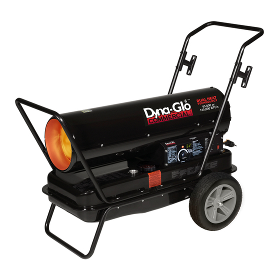
- Page 3 Front Guard Hot Air Outlet Upper Shell Handle Fan Guard Lower Shell BTU Control Switch Fuel Tank Cord Wrap Side Cover Pressure Gauge Lamp Fuel Gauge Thermostot Knob Fuel Cap Power/Reset Switch Power Cord (Piggy Back) Figure 1. KFA80C MODEL...
- Page 4 NEVER LEAVE THE HEATER UNATTENDED WHILE BURNING! Front Handle Rear Handle Upper Shell Hot Air Outlet Shell Lower Cord Wrap Fuel Gauge BTU Control Switch Fuel Cap Side Cover Pressure Gauge Lamp Fan Guard Thermostot Knob Room Temp. Display Power Cord Power/Reset Switch (Piggy Back) 10”...
-
Page 5: Unpacking And Assembly
KFA80C KFA135C KFA220C Wheel Support Frame Wheel Threaded Axle Front Handle Rear Handle Hardware kit : HW-KFA1016 Figure 4. KFA80C MODEL Handle Cord Wraps Figure 5. KFA135C/ KFA220C MODELS Screws Flange Screws Nuts Cap Nuts S Cap Nuts L Bushings Wheels (10"... - Page 6 NEVER LEAVE THE HEATER UNATTENDED WHILE BURNING! 2. ASSEMBLY Screw Handle Front Guard Remove Screws KFA80C Model only (Assembly time for this product is minutes) Wedged Portion Tools Required Slit Hole • Medium Phillips Screwdriver. 1) Lift front guard for arrow direction and Shell Upper make sure that guard’s wedged portion...
- Page 7 NEVER LEAVE THE HEATER UNATTENDED WHILE BURNING! Front Handle Screw Cap Nut S Rear Handle Hot Air Outlet Cord Wrap Flange Screw Fuel Tank Flange Air Inlet Wheel Support Frame Threaded Axle Wheel Bushing Wheel Cap Nut L Figure 7. Assembling Handle, Wheel and Cord wrap CAUTION : DO NOT OPERATE heater without support frame assembled to tank.
- Page 8 If this device activates and turns your heater off it may require service. Internal Shut-Off Temp. Reset Temperature MODELS Plus/Minus 10 Degrees Plus/Minus 10 Degrees KFA80C 158˚F/70˚C 104˚F/40˚C KFA135C 158˚F/70˚C 104˚F/40˚C KFA220C 194˚F/90˚C...
-
Page 9: Fueling Your Heater
NEVER LEAVE THE HEATER UNATTENDED WHILE BURNING! 6. FUELING YOUR HEATER NEVER FILL THE HEATER FUEL TANK IN THE LIVING SPACE : FILL THE TANK OUTDOORS. DO NOT OVERFILL YOUR HEATER AND BE SURE HEATER IS LEVELED. IMPORTANT NOTICE REGARDING FIRST IGNITION OF HEATER : The first time you light the heater, it should be done outdoors. -
Page 10: Long Term Storage Of Your Heater
Power Switch Thermostat Power Switch Relief Valve Control Knob Control Knob KFA80C Model KFA135C/220C Models Fan Guard Figure 8. Controls for All Models NOTICE : The major electrical components of this heater are protected by a safety fuse mounted to the PCBboard. -
Page 11: Maintenance
NEVER LEAVE THE HEATER UNATTENDED WHILE BURNING! 9. MAINTENANCE WARNING!! : NEVER SERVICE HEATER WHILE IT IS PLUGGED IN OR WHILE HOT! USE ORIGINAL EQUIPMENT REPLACEMENT PARTS. Use of third party or other alternate components will void warranty and may cause unsafe operating conditions. - Page 12 NEVER LEAVE THE HEATER UNATTENDED WHILE BURNING! E.) NOZZLE REMOVE DIRT IN NOZZLE AS NEEDED (SEE PAGE 16). Combustion Chamber (For KFA80C/135C Models Only) Screw - Remove upper shell (See page 10). Ignitor Wire - Remove fan blade (See page 10).
- Page 13 NEVER LEAVE THE HEATER UNATTENDED WHILE BURNING! F.) SPARK PLUG CLEAN AND REGAP EVERY 600 HOURS OPERATION OR REPLACE AS NEEDED. (For KFA80C/135C Models Only) - Remove upper shell (See page 10). - Remove fan (See page 10). Spark Plug Nozzle Adaptor - Remove ignitor wire from spark plug.
-
Page 14: Pump Pressure Adjustment
- Pull fuel line off fuel filter neck. - Turn fuel filter 90˚ to counter clockwise and pull to remove (KFA80C Model only). - Turn fuel filter 90˚ to clockwise and pull to remove (KFA135C/220C Models only). -
Page 15: Replacing Fuse
NEVER LEAVE THE HEATER UNATTENDED WHILE BURNING! 10. REPLACING FUSE NOTICE : This heater is fuse protected. If your heater fails to ignite, DO NOT RETURN YOUR HEATER TO THE STORE. Please follow the simple instruction below to inspect and change the fuse. PROCEDURE FOR REPLACING FUSE WARNING : SHOCK HAZARD To prevent personal injury, unplug the power cord before replacing fuse. -
Page 16: Troubleshooting Guide
NEVER LEAVE THE HEATER UNATTENDED WHILE BURNING! 11. TROUBLE SHOOTING GUIDE TROUBLE POSSIBLE CAUSE CORRECTIVE ACTION Heater ignites but MAIN PCB 1. Wrong pump pressure 1. See Pump Pressure Adjustment, assembly shuts heater off after Page 13. a short period of time. 2. -
Page 17: Wiring Diagram
ORANGE BLACK PUMP ROOM WHITE MOTOR SENSOR CAPACITOR GREEN THERMOSTAT CN2(AC2)/ (TEMP. CONTROL) EARTH CN1(AC1)/ BLACK PHOTO CELL BLACK MODEL CAPACITOR KFA80C 15uF/230VAC POWER LIMIT POWER KFA135C/220C 20uF/350VAC FUSE SWITCH CONTROL PLUG 8A/125VAC BLACK BLACK AC120V 60Hz GREEN WHITE EARTH... -
Page 18: Specifications
NEVER LEAVE THE HEATER UNATTENDED WHILE BURNING! 13. SPECIFICATIONS 32.0"(813mm) 11.7"(297mm) KFA80C Model KFA135C KFA220C 41.9"(1,063 ) 47.4"(1,205 ) 21.5"(547 ) 23.1"(587 ) 33.5"(850 ) 32.4"(824 ) KFA135C / KFA220C Models MODEL KFA80C KFA135C KFA220C HIGH 80,000 135,000 220,000 BTU/Hr. - Page 19 NEVER LEAVE THE HEATER UNATTENDED WHILE BURNING! EXPLODED PARTS DRAWING (KFA80C/135C Models Only) NOTE : SPECIFY MODEL NUMBER AND PART NUMBER WHEN ORDERING PARTS. BURNER HEAD ASSEMBLY 20-8 20-7 20-3 20-5 20-1 20-2 20-4 20-6 18 19 MOTOR AND PUMP ASSEMBLY...
-
Page 20: Parts List
NEVER LEAVE THE HEATER UNATTENDED WHILE BURNING! 15. PARTS LIST (KFA80C/135C Models Only) PART NO. Quantity KEY NO. DESCRIPTION KFA80C KFA135C Fuel Tank Assembly 2151-0047-01 2151-0048-01 Fuel Drain-Bolt 4329-0072-00 Fuel Gauge 2156-0049-00 2156-0051-00 Fuel Filter Assembly 2155-0005-00 2155-0001-00 Fuel Cap... - Page 21 NEVER LEAVE THE HEATER UNATTENDED WHILE BURNING! 15. PARTS LIST (KFA80C/135C Models Only) PART NO. Quantity KEY NO. DESCRIPTION KFA80C KFA135C 23-10 Insert See SP-KFA1000 See SP-KFA1000 23-11 End Pump Cover 3531-0027-00 3531-0027-00 23-12 Elbow 3231-0181-00 3231-0181-00 23-13 Lint Filter...
- Page 22 NEVER LEAVE THE HEATER UNATTENDED WHILE BURNING! EXPLODED PARTS DRAWING (KFA220C Model Only) NOTE : SPECIFY MODEL NUMBER AND PART NUMBER WHEN ORDERING PARTS. BURNER HEAD ASSEMBLY 18-8 18-3 18-7 18-1 18-5 18-2 18-4 18-6 20 11 22 10 MOTOR AND PUMP ASSEMBLY 21-2 21-5 21-6...
- Page 23 NEVER LEAVE THE HEATER UNATTENDED WHILE BURNING! 15. PARTS LIST (KFA220C Model Only) PART NO. Quantity KEY NO. DESCRIPTION KFA220C Fuel Tank Assmebly 2151-0049-01 Fuel Drain-Bolt 4329-0072-00 Fuel Gauge 2156-0052-00 Fuel Filter Assmbly 2155-0001-00 Fuel Cap 2151-0041-00 Power Cord 3980-0275-00 Shell Lower 3111-0504-03 Flange Screw...
- Page 24 NEVER LEAVE THE HEATER UNATTENDED WHILE BURNING! 15. PARTS LIST (KFA220C Model Only) PART NO. Quantity KEY NO. DESCRIPTION KFA220C 21-12 Elbow 3231-0181-00 21-13 Lint Filter See SP-KFA1005 21-14 Bolt Flange 4329-0016-00 21-15 Output Filter See SP-KFA1005 21-16 End Filter Cover 3221-0076-00 21-17 Ball...
-
Page 25: Parts List (Wheels And Handle)
NEVER LEAVE THE HEATER UNATTENDED WHILE BURNING! 15. PARTS LIST (WHEELS AND HANDLE) 1) KFA80C MODEL PART NO. Quantity KEY NO. DESCRIPTION KFA80C Handle 3231-0073-00 Cord Wrap 3221-0041-00 KFA135C/220C MODELS PART NO. Quantity KEY NO. DESCRIPTION KFA135C KFA220C Front Handle... - Page 27 Warranty LIMITED WARRANTY: This limited warranty is extended to the original retail purchaser of this Forced Air/Convection/Radiant Heater and warrants against any defect in materials and workmanship for a period of one (1) year from the date of retail sale.GHP Group, Inc., at it’s option, will either provide replacement parts or replace or repair the unit, when properly returned to the retailer where purchased or one of our service centers as directed by GHP Group,Inc., within one (1) year of retail purchase.
-
Page 28: Warranty Registration
WARRANTY REGISTRATION days of date of purchase. You can also register your warranty on the internet at www.ghpgroupinc.com. Complete the entire serial number. Retain this portion of the card for your records. GHP Group, Inc. 6440 W Howard St Niles, IL 60714-3302 Tel: (877) 447-4768 www.ghpgroupinc.com SAVE THIS CARD!
Need help?
Do you have a question about the KFA80C and is the answer not in the manual?
Questions and answers