Arcom RC210 Hardware Manual
Repeater controller
Hide thumbs
Also See for RC210:
- Operation manual (68 pages) ,
- Operation and programming manual (58 pages) ,
- Assembly manual (8 pages)
Table of Contents
Advertisement
Quick Links
Arcom Communications
24035 NE Butteville Rd
Aurora, Oregon 97002
(503) 678-6182
arcom@ah6le.net
http://www.arcomcontrollers.com/
RC210 Repeater Controller
Hardware Manual
Hardware Version 3.0a
April 25, 2005
Reproduction or translation of any part of this manual beyond that permitted by sections 107 or 108 of the 1976 United States Copyright Act (or its legal successor)
without the express written permission of Arcom Communications is unlawful as noted below. Requests for permission to copy or for further information should be
addressed to Arcom Communications. Except as noted above, permission is hereby granted for any non-profit group or individual to reproduce any portion of this
document provided that: the reproduction is not sold for profit; the intent of reproduction is to further disseminate information on the RC210 Repeater Controller kit; the
reproduction is not used for advertising or otherwise promoting any specific commercial product other than the RC210; and full credit is given to Arcom Communications
as the original source of information.
The information contained in the manual has been carefully checked for accuracy and is believed to be entirely reliable. However, no responsibility is assumed for
inaccuracies. Arcom Communications reserves the right to make changes in the RC210 Repeater Controller kit to improve reliability, function or design without obligation
to purchasers of previous equipment. Arcom Communications does not assume any liability arising out of the application or use of any product or circuit described herein;
neither does it convey license under its patent rights or the rights of others.
Advertisement
Table of Contents

Subscribe to Our Youtube Channel
Related Manuals for Arcom RC210


Summary of Contents for Arcom RC210
- Page 1 Arcom Communications. Except as noted above, permission is hereby granted for any non-profit group or individual to reproduce any portion of this document provided that: the reproduction is not sold for profit; the intent of reproduction is to further disseminate information on the RC210 Repeater Controller kit; the reproduction is not used for advertising or otherwise promoting any specific commercial product other than the RC210;...
- Page 2 (This page intentionally blank)
-
Page 3: Table Of Contents
........................... 18 UDIO ELAY XPANSION EADERS COS A PTT O ..........................18 HECKING PERATION ............................... 18 ETTING UDIO EVELS ARCOM COMMUNICATIONS NO-NONSENSE LICENSE AGREEMENT FOR THE OPERATING FIRMWARE OF THE RC210 REPEATER CONTROLLER .................... 19 PC BOARD COMPONENT PLACEMENT ..........................21... -
Page 4: Introduction
RC210 owner. Installing updates requires no more than a computer running Windows 95/98/NT/2000/XP with a serial (or USB) port. With the RC210, you just download the free update and upload it into your RC210... -
Page 5: Description Of Features
Control Receiver Because of the RC210's ability to control any Port from any other Port, there is no need for a special, dedicated control receiver port. By using the right combination of Macro Functions, you can easily and quickly disable or enable any function the RC210 is capable of performing. -
Page 6: A Word About Identification
All the command codes may be programmed to your own, special and unique code. This makes the RC210 very easy to incorporate into existing systems without users having to relearn code structures. -
Page 7: Hardware Reference
The RC210 requires anywhere from +11.5 to +15 vdc at 60 ma. This voltage source should be clean, filtered DC. Power connection is made through a Phoenix power connector and the mating plug is included with the RC210. There is no need to worry about using a fuse, as the RC210 is protected by an on-board, self-resetting fuse. -
Page 8: Sub-Audible Tone Decoder
If this option is used, the controller can be commanded to require users to use sub-audible tone with their transmissions on that port. The RC210 accomodates either a logic high (5 to 15 vdc) or a logic low (<... -
Page 9: Dtmf Decoders
LEDs do not have to be powered up, the push-on jumper on JP13 may be removed. If mounting the RC210 in a cabinet, a switch may be connected to JP13 to allow the operator to conveniently turn the LEDs on and off as needed. -
Page 10: Radio Connections
Radio Connections Each port connector provides all connections needed for your radios. The RC210 comes with two versions of connectors - DB9 computer style connectors or RJ45 modular jacks. 9-Pin RJ-45 Direction Name/Description -----► Control OUT CTCSS Encode Logic IN ◄-----... -
Page 11: I/O Connections
I/O Connections The RC210 supports connecting external devices (other than radios of course) by the use of a DB25 connector. The pinout is as follows: Name Description Name Description Analog Channel 1 Logic Output 6 Analog Channel 2 Logic Output 7... -
Page 12: Analog Inputs
Analog Inputs The RC210 allows you to connect external analog devices and readback their value on command. This is typically used for remote monitoring of such things as backup battery voltage, transmitter power, etc. There are 8 "meters" corresponding to the 8 Analog inputs. -
Page 13: Current
LM355 on ADC channels 1 & 2. This allows you to eliminate some external parts by installing 4.7K resistors right on the board. These resistors are not provided but if you install them, there are only 2 connections between the sensor and RC210 necessary. -
Page 14: Measuring Power
"compressed" at the high end. This is due to the fact that power is proportional to voltage or current squared (this is known as a logarithmic scale). The power meter face in the RC210 takes this into account when taking a measurement. -
Page 15: Logic Outputs
Logic Outputs The RC210 provides 7 general purpose outputs (expandable to 32) that you can use to switch electronic devices on and off at your repeater site. While these outputs are buffered by open collector transistors, care should be used so as not to exceed their across it. -
Page 16: Serial Data Input/Output
2 Gnd If your radio requires TTL level (it requires a level converter to connect to a computer), you can hook it directly to the RC210 without the need for an external converter by using J4, the A/D and I/O connector. Typical radios would be those such as the Icom IC-706MkIIg. - Page 17 If you remove the cover of the radio, you will see gold plated pads near the power connections. These pads are normally used in the E model (European) to connect a pigtail, which then provides the necessary signal access for packet use. These will supply the needed connections (other than programming) to the RC210 for remote base use as well. PAD NAME...
-
Page 18: Audio Delay Expansion Headers
Once connections are made, the next step is to verify that COS and PTT are operating properly. There are a series of LED's on the RC210 that are used to indicate the status of various functions. Their function is marked on the PC board. They may be turned off to save power when you don't need them by removing the jumper from JP13. -
Page 19: Arcom Communications No-Nonsense License Agreement For The Operating Firmware Of The Rc210 Repeater Controller
BY DOWNLOADING OR OTHERWISE USING THE FIRMWARE, YOU AGREE TO BE BOUND BY ALL OF THE TERMS AND CONDITIONS OF THIS LICENSE AGREEMENT. Upon your acceptance of the terms and conditions of the License Agreement, Arcom Communications grants you the right to use the Firmware in the manner provided below. -
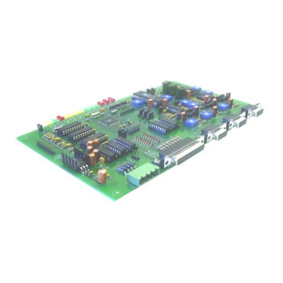
Page 21: Pc Board Component Placement
PC Board Component Placement...
Need help?
Do you have a question about the RC210 and is the answer not in the manual?
Questions and answers