Table of Contents
Advertisement
Available languages
Available languages
Quick Links
Download this manual
See also:
Instruction Manual
Advertisement
Table of Contents
Troubleshooting

Related Manuals for ESAB EPP-200


Summary of Contents for ESAB EPP-200
- Page 1 EPP-200 Precision Plasmarc Cutting Console Instruction Manual Instruction Manual Instruction Manual Instruction Manual Instruction Manual 0558004676 10 / 2007...
-
Page 2: User Responsibility
BE SURE THIS INFORMATION REACHES THE OPERATOR. YOU CAN GET EXTRA COPIES THROUGH YOUR SUPPLIER. CAUTION These INSTRUCTIONS are for experienced operators. If you are not fully familiar with the principles of operation and safe practices for arc welding and cutting equipment, we urge you to read our booklet, “Precautions and Safe Practices for Arc Welding, Cutting, and Gouging,”... - Page 3 TABLE OF CONTENTS SECTION SECTION SECTION SECTION SECTION TITLE TITLE TITLE TITLE TITLE PAGE PAGE PAGE PAGE PAGE PARAGRAPH PARAGRAPH PARAGRAPH PARAGRAPH PARAGRAPH SECTION 1 SECTION 1 SECTION 1 SECTION 1 SECTION 1 SAFETY SAFETY SAFETY SAFETY SAFETY ......................................................
- Page 4 TABLE OF CONTENTS TABLE OF CONTENTS TABLE OF CONTENTS TABLE OF CONTENTS TABLE OF CONTENTS...
-
Page 5: Safety Precautions
SECTION 1 SAFETY PRECAUTIONS 5. Do not use equipment beyond its ratings. For example, WARNING: hese Safety Precautions are for overloaded welding cable can overheat and create a fire your protection. They summarize precaution- hazard. ary information from the references listed in 6. - Page 6 SECTION 1 SAFETY PRECAUTIONS EQUIPMENT MAINTENANCE -- Faulty or im- FUMES AND GASES -- Fumes and properly maintained equipment can cause gases, can cause discomfort or harm, injury or death. Therefore: particularly in confined spaces. Do not breathe fumes and gases. Shield- 1.
- Page 7 SECTION 1 PRECAUCION DE SEGURIDAD usted esta entrenado para su uso. ADVERTENCIA: Estas Precauciones de Seguridad No use el equipo fuera de su rango de operación. Por ejemplo, son para su protección. Ellas hacen resumen de el calor causado por cable sobrecarga en los cables de soldar información proveniente de las referencias listadas pueden ocasionar un fuego.
- Page 8 SECTION 1 PRECAUCION DE SEGURIDAD HUMO Y GASES -- El humo y los gases, MANTENIMIENTO DEL EQUIPO -- Equipo pueden causar malestar o daño, defectuoso o mal mantenido puede causar particularmente en espacios sin daño o muerte. Por lo tanto: ventilación.
- Page 9 SECTION 1 PRÉCAUTIONS DE SÉCURITÉ observer les précautions suivantes: AVERTISSEMENT: Ces règles de sécurité ont pour objet a. Éloigner suffisamment tous les matériaux combustibles d’ assurer votre protection. Veillez à lire et à observer les du secteur où l’on exécute des soudures ou des coupes précautions énoncées ci-dessous avant de monter l’...
- Page 10 52529 “Precautions and Safe Practices for Arc Weld- formation poches d’hydrogène, lesquelles ing, Cutting and Gouging” publié par ESAB. Nous conseillons également de consulter les publications présentent un danger d’explosion; ce ventilateur ne sui-vantes, tenues à votre disposition par l’American fonctionne que si l’interrupteur correspondant du panneau avant se trouve placé...
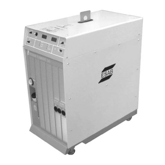
- Page 11 DESCRIPTION DESCRIPTION 2.1 Introduction The EPP 200 Power Console is designed for mechanized plasma applications. It can be used with other ESAB products such as the PT-24 and PT-600 torches, an optional plumbing box and a remote set-up pendant. •...
- Page 12 WARNING WARNING Electric Shock Can Kill! Use of torches not designed for this console could result in a hazardous electric shock. Use only torches designed for the EPP-200 Console. 2.3 Dimensions and Weight 22in. (550mm) 44 in. (1100mm) 42in. (1050mm)
- Page 13 SECTION 2 DESCRIPTION 2.4 EPP-200 Options and Accessories Options * Cooling Water Hoses (2) Control Cable Pilot Arc Lead Power Lead Console to Plumbing Box Plumbing Box to Console Plumbing Box to Console Console to Plumbing Box 5 ft. (1.5m)
- Page 14 SECTION 2 DESCRIPTION 2.5 Gas Hoses Gas Type 25 ft. 50 ft. 75 ft. 100 ft. 125 ft. (7.6m) (15.2m) (22.8m) (30.4m) (38.1m) Nitrogen (clear) 33122 33123 33124 33125 33126 Oxygen (clear - USA) 33117 33118 33119 33120 33121 Oxygen (blue - Euro) 0558002973 0558002974 0558002975 0558002976 0558002977 Argon/Hydrogen (H-35) (1) 33122* 33123*...
- Page 15 SECTION 2 DESCRIPTION 2.7 Basic Packages The EPP-200 system is available as a pre-engineered package or can be ordered as individual parts as listed. Basic Packages include: EPP-200 Console • Plasma Torch • Appropriate regulators for the gases indicated •...
- Page 16 SECTION 2 DESCRIPTION...
- Page 17 SECTION 3 SECTION 3 SECTION 3 SECTION 3 SECTION 3 INSTALLATION INSTALLATION INSTALLATION INSTALLATION INSTALLATION 3.1 General WARNING WARNING WARNING WARNING WARNING Failure To Follow Instructions Could Lead To Death, Injury Or Damaged Property Follow these instructions to prevent injury or property damage.
- Page 18 A minimum of 2 ft. (0.61m) clearance for cooling air flow. Plan for top panel and side panels having to be removed • for maintenance, cleaning and inspection. Locate the EPP-200 relatively close to a properly fused • electrical power supply. Plasma Keep area beneath power source clear for cooling air •...
- Page 19 INSTALLATION INSTALLATION 3.4.1 Primary Power Specifications EPP-200 is a 3-phase unit. Input power must be provided from a line (wall) disconnect switch that contains fuses or circuit breakers in accordance to local or state regulations. Recommended input conductor and line fuse sizes:...
- Page 20 SECTION 3 SECTION 3 INSTALLATION INSTALLATION SECTION 3 SECTION 3 SECTION 3 INSTALLATION INSTALLATION INSTALLATION 3.4.2 Primary Power Hookup Procedure The following procedure explains the proper installation steps for connecting primary electrical power to the plasma console. Input Power Cable Strain Relief NOTE: Safety codes specify the power ground wire be the last connection to break should the cable be pulled...
- Page 21 SECTION 3 SECTION 3 SECTION 3 SECTION 3 SECTION 3 INSTALLATION INSTALLATION INSTALLATION INSTALLATION INSTALLATION 9. Connect input conductors to line (wall) disconnect. 10. Replace side panel. Replace only if all connections have made. Output connections require this panel to be removed. 11.
- Page 22 SECTION 3 SECTION 3 SECTION 3 INSTALLATION INSTALLATION INSTALLATION INSTALLATION INSTALLATION 3.5 Connecting Plasma Torches to EPP-200 Console and Options 3.5.1 EPP-200 Output Cables, Hoses and Adapters (customer supplied) EPP-200: Lengths vary depending on system. Coolant Return • Coolant Supply •...
- Page 23 SECTION 3 SECTION 3 INSTALLATION INSTALLATION SECTION 3 SECTION 3 SECTION 3 INSTALLATION INSTALLATION INSTALLATION Coolant Installation WARNING WARNING WARNING WARNING WARNING Electric Current Is Hazardous. It is important to have a good earth ground connected to the workpiece or cutting table. CA UTION UTION UTION...
- Page 24 SECTION 3 SECTION 3 SECTION 3 SECTION 3 SECTION 3 INSTALLATION INSTALLATION INSTALLATION INSTALLATION INSTALLATION...
- Page 25 SECTION 4 SECTION 4 OPERATION OPERATION SECTION 4 SECTION 4 SECTION 4 OPERATION OPERATION OPERATION 4.1 Introduction – Operational Safety D D D D D ANGER ANGER ANGER ANGER ANGER Electric Shock Can Kill! Disconnect current supply at wall disconnect before servicing console, torch or plumbing box.
- Page 26 OPERATION OPERATION SECTION 4 SECTION 4 SECTION 4 OPERATION OPERATION OPERATION 4.2 Operating the EPP-200 Console 4.2.1 Console Controls Pilot Arc High/Low Switch Cutting Voltage and Cutting Current Meters Output Current Control Remote/Panel Selection Switch Gas Test Switch Fault Lights...
- Page 27 SECTION 4 SECTION 4 SECTION 4 SECTION 4 SECTION 4 OPERATION OPERATION OPERATION OPERATION OPERATION Gas Test Switch Cut – Allows for setup of cut gas pressure and flow. Start/ Shield – Setup of gas pressures and flows. Operate – Default position – Must be in this position for cutting.
- Page 28 SECTION 4 SECTION 4 OPERATION OPERATION SECTION 4 SECTION 4 SECTION 4 OPERATION OPERATION OPERATION 4.3 Sequence of Operation 1. Apply power by closing the line (wall) switch. Main power light will not illuminate until console power switch is turned ON.
- Page 29 Only trained personnel should perform maintenance or repairs CAUTION on this equipment. 5.2 Inspection and Cleaning Frequent inspection and cleaning of the EPP-200 and related equipment are recommended for safety and proper operation. Consider the following during inspection and cleaning: • Check work cable to workpiece connection.
- Page 30 SECTION 5 MAINTENANCE Flying Debris Hazard. WARNING Flying Debris Can Seriously Injure Eyes Wear protective eyewear when cleaning with compressed air. Use low pressure air only. Avoid Potential Equipment Damage CAUTION Water and/or oil can accumulate in compressed air lines. Be sure to direct the first air blast away from equipment to avoid damaging the junction box or flow control box.
- Page 31 SECTION 5 MAINTENANCE 5.3 Gas Manifold Pressure Switches Newer EPP-200 consoles are equipped with nonadjustable preset gas manifold pressure switches. Older ESP-200 consoles have adjustable pressure switches. Both type switches are preset for: • 17 psig (1.2 bar), shield and start gas switches • 22 psig (1.5 bar), cut gas switch 5.3.1 Pressure Switch Adjustment Procedure Turn main power switch OFF OFF.
- Page 32 SECTION 5 MAINTENANCE...
- Page 33 SECTION 6 TROUBLESHOOTING 6.1 Introduction Electric Shock Can Kill! WARNING Ensure all primary power to machine has been externally disconnected. Open line (wall) switch before attempting inspection or performing work inside the plasma console or plumbing box. Capacitors Can Store High Voltages. WARNING Disconnecting plasma console does not ensure capacitors are de- energized. Ensure console capacitors are grounded after removing power and prior to performing maintenance.
-
Page 34: Troubleshooting
SECTION 6 TROUBLESHOOTING 6.3 Front Panel Fault Lights Fault Indicator Lights • Coolant Flow – Will show low coolant flow. The light will briefly show a fault when console is turned on and then go out. • Plasma Gas Pressure — fault indicator – low plasma gas pressure. Torch will not fire when indicated. - Page 35 SECTION 6 TROUBLESHOOTING 6.4 Troubleshooting Guide SECTION 6 Troubleshooting High Voltages Can Cause Serious Injury or Death! 6.4 Troubleshooting Guide WARNING High Voltages Can Cause Serious Voltages in plasma cutting equipment are high enough to cause WARNING serious injury or death. Injury or Death! Only trained technicians should attempt diagnosis and repair of Voltages in plasma cutting equipment are high...
- Page 36 SECTION 6 TROUBLESHOOTING SECTION 6 Troubleshooting Problem Problem Problem Problem Possible Cause Possible Cause Possible Cause Possible Cause Corrective Action Corrective Action Corrective Action Corrective Action Power Source Temp fault Power Source Temp fault Power Source Temp fault Power Source Temp fault 1) Poor ventilation at rear of 1) Make sure that there is 2 feet of console.
- Page 37 SECTION 6 TROUBLESHOOTING SECTION 6 Troubleshooting Problem Problem Problem Problem Possible Cause Possible Cause Possible Cause Possible Cause Corrective Action Corrective Action Corrective Action Corrective Action LEDX on MOD1 not ON LEDX on MOD1 not ON LEDX on MOD1 not ON LEDX on MOD1 not ON LEDX on MOD2 not ON LEDX on MOD2 not ON...
- Page 38 SECTION 6 TROUBLESHOOTING...
- Page 39 The serial number is stamped on the unit nameplate. 7.2 Ordering To ensure proper operation, it is recommended that only genuine ESAB parts and products be used with this equipment. The use of non-ESAB parts may void your warranty. Replacement parts may be ordered from your ESAB Distributor.
- Page 40 SECTION 7 REPLACEMENT PARTS...
- Page 41 SECTION 7 REPLACEMENT PARTS...
- Page 42 SECTION 7 REPLACEMENT PARTS...
- Page 43 SECTION 7 REPLACEMENT PARTS...
- Page 44 SECTION 7 REPLACEMENT PARTS...
- Page 45 SECTION 7 REPLACEMENT PARTS...
- Page 46 SECTION 7 REPLACEMENT PARTS...
- Page 47 SECTION 7 REPLACEMENT PARTS...
- Page 48 SECTION 7 REPLACEMENT PARTS...
- Page 49 SECTION 7 REPLACEMENT PARTS...
- Page 50 SECTION 7 REPLACEMENT PARTS...
- Page 51 SECTION 7 REPLACEMENT PARTS...
- Page 52 SECTION 7 REPLACEMENT PARTS...
- Page 53 SECTION 7 REPLACEMENT PARTS...
- Page 54 SECTION 7 REPLACEMENT PARTS...
-
Page 55: Revision History
Revision History Original release February, 2004 May, 2004 - Converted Schematics and Wiring Diagrams to 11' x 17' page size and included at back of manual. June, 2004 - Updated Options, Accessories and Hose charts on Pages 13 and 14. November, 2004 - Changed bom item 69 from: clamp hose w/d .25d - .62d qty: 12 to: clamp hose w/d .31d - .88d qty: 6. February, 2006 - Updated Schematic and Replacement Parts per ECN #053186. November, 2006 - Updated Replacement Parts December, 2006 - Updated Replacement Parts October, 2007 - Updated conductor / fuse table in Subsection 3.4.1. Updated disclaimer page. - Page 62 ESAB Welding & Cutting Products, Florence, SC Welding Equipment COMMUNICATION GUIDE - CUSTOMER SERVICES A. CUSTOMER SERVICE QUESTIONS: Telephone: (800)362-7080 / Fax: (800) 634-7548 Hours: 8:00 AM to 7:00 PM EST Order Entry Product Availability Pricing Order Information Returns B. ENGINEERING SERVICE:...
Need help?
Do you have a question about the EPP-200 and is the answer not in the manual?
Questions and answers