Advertisement
Quick Links
Advertisement

Related Manuals for ESAB EPP-200


Summary of Contents for ESAB EPP-200
- Page 1 EPP-200 Precision Plasmarc Cutting System Instruction Manual 0558007005 10 / 2007...
- Page 2 BE SURE THIS INFORMATION REACHES THE OPERATOR. YOU CAN GET EXTRA COPIES THROUGH YOUR SUPPLIER. CAUTION These INSTRUCTIONS are for experienced operators. If you are not fully familiar with the principles of operation and safe practices for arc welding and cutting equipment, we urge you to read our booklet, “Precautions and Safe Practices for Arc Welding, Cutting, and Gouging,”...
- Page 3 TABLE OF CONTENTS SECTION TITLE PAGE SECTION 1 SAFETY ............................ 5 SECTION 2 DESCRIPTION ................................7 SECTION 3 INSTALLATION ..............................13 SECTION 4 OPERATION ................................21...
- Page 4 Plasma Cutting Console Brand name or trade mark Fabrikatnamn eller varumärke ESAB Type designation etc. Typbeteckning etc. EPP-200, (0558004315) Manufacturer or his authorised representative established within the EEA Name, address, telephone No, telefax No: Tillverkarens namn, adress, telefon, telefax: ESAB AB Esabvägen, SE-695 81 Laxå, Sweden...
-
Page 5: Safety
SAFETY PRECAUTIONS Safety Precautions Users of ESAB welding and plasma cutting equipment have the ultimate responsibility for ensuring that anyone who works on or near the equipment observes all the relevant safety precautions. Safety precautions must meet the requirements that apply to this type of welding or plasma cutting equipment. The following recommendations should be observed in addition to the standard regulations that apply to the workplace. - Page 6 SECTION 1 SAFETY PRECAUTIONS WELDING AND PLASMA CUTTING CAN BE INJURIOUS TO YOURSELF AND WARNING OTHERS. TAKE PRECAUTIONS WHEN WELDING OR CUTTING. ASK FOR YOUR EMPLOYER’S SAFETY PRACTICES WHICH SHOULD BE BASED ON MANUFACTURERS’ HAZARD DATA. ELECTRIC SHOCK - Can kill. - Install and earth (ground) the welding or plasma cutting unit in accordance with applicable standards.
-
Page 7: Description
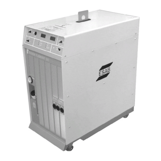
DESCRIPTION 2.1 Introduction The EPP-200 Power Console is designed for mechanized plasma applications. It can be used with other ESAB products such as the PT-24 and PT-600 torches, an optional plumbing box and a remote set-up pendant. power semiconductor components 2.2 General Specifications... - Page 8 Electric Shock Can Kill! WARNING Use of torches not designed for this console could result in a haz- ardous electric shock. Use only torches designed for the EPP-200 Console. 2.3 Dimensions and Weight 22in. (550mm) 44 in. (1100mm) 42in. (1050mm)
- Page 9 SECTION 2 DESCRIPTION 2.4 EPP-200 Options and Accessories Options * Cooling Water Hoses (2) Control Cable Pilot Arc Lead Power Lead Console to Plumbing Box Plumbing Box to Console Plumbing Box to Console Console to Plumbing Box 5 ft. (1.5m)
- Page 10 SECTION 2 DESCRIPTION 2.5 Gas Hoses Gas Type 25 ft. 50 ft. 75 ft. 100 ft. 125 ft. (7.6m) (15.2m) (22.8m) (30.4m) (38.1m) Nitrogen (clear) 33122 33123 33124 33125 33126 Oxygen (clear - USA) 33117 33118 33119 33120 33121 Oxygen (blue - Euro) 0558002973 0558002974 0558002975...
- Page 11 SECTION 2 DESCRIPTION 2.7 Basic Packages The EPP-200 system is available as a pre-engineered package or can be ordered as individual parts as listed. Basic Packages include: NOTE: Part Numbers in parenthesis apply to "CE"/European units only. Torch Coolant (25%) – 1 gallon (3.8 L) P/N 0558004297 25% PG coolant improves electrode life in applications using oxygen or (-40.0°...
- Page 12 SECTION 2 DESCRIPTION...
-
Page 13: Installation
SECTION 3 INSTALLATION 3.1 General Failure To Follow Instructions Could Lead To Death, WARNING Injury Or Damaged Property You must comply with local, state and national electrical and safety codes. 3.2 Unpacking Use Lifting Eye When Hoisting From Overhead CAUTION Use safe practices when transporting with overhead method. - Page 14 SECTION 3 INSTALLATION Do Not Restrict Air Flow CAUTION Restricting intake air with any type of filter on or around the Plasma console will result in overheating and may void the warranty. 3.3 Placement for maintenance, cleaning and inspection. electrical power supply. Plasma Console flow.
- Page 15 SECTION 3 INSTALLATION 3.4.1 Primary Power Specifications EPP-200 is a 3-phase unit. Input power must be provided from a line (wall) disconnect switch that contains fuses or circuit breakers in accordance to local or state regulations. Recommended input conductor and line fuse sizes:...
- Page 16 SECTION 3 INSTALLATION 3.4.2 Primary Power Hookup Procedure The following procedure explains the proper installation steps for connecting primary electrical power to the plasma console. Input Power Cable NOTE: Safety codes specify the power ground wire be the last Strain Relief connection to break should the cable be pulled out of the unit.
- Page 17 SECTION 3 INSTALLATION Electric Current Is Hazardous. WARNING It is important to have a good earth ground connected to the workpiece or cutting table. 9. Connect input conductors to line (wall) disconnect. Work ground to work piece 10. Replace side panel. Replace only if all connections have made. Output connections require this panel to be removed.
- Page 18 Lengths vary depending on system. See Description, Section 2 for part numbers. A remote SETUP Panel option is available on Avenger 1 and larger ESAB cut cutting machines. This panel operates the same as the pendant. Refer to your machine manual for replacement parts.
- Page 19 SECTION 3 INSTALLATION Coolant Installation Electric Current Is Hazardous. WARNING It is important to have a good earth ground connected to the workpiece or cutting table. Commercial Antifreeze Will Cause Torch To CAUTION Malfunction. Use special torch coolant. Do to high electrical conductivity, DO NOT use tap water or commercial automotive type antifreeze for torch cooling.
- Page 20 SECTION 3 INSTALLATION...
-
Page 21: Operation
SECTION 4 OPERATION 4.1 Introduction – Operational Safety Electric Shock Can Kill! DANGER Disconnect current supply at wall disconnect before servicing console, torch or plumbing box. removed/open. system unless power has been disconnected at the wall disconnect. This equipment can be hazardous if not properly WARNING operated and maintained. - Page 22 SECTION 4 OPERATION 4.2 Operating the EPP-200 Console 4.2.1 Console Controls Pilot Arc High/Low Switch Cutting Voltage and Cutting Current Meters Output Current Control Remote/Panel Selection Switch Gas Test Switch Main Power Switch Pilot Arc Switch Used to select pilot arc current range when Remote / Panel Switch is in the Panel position.
- Page 23 SECTION 4 OPERATION Gas Test Switch Cut – Allows for setup of cut gas pressure and flow. Start/Shield – Setup of gas pressures and flows. Operate – Default position – Must be in this position for cutting. Fault Indicator Lights Coolant Flow –...
- Page 24 SECTION 4 OPERATION 4.3 Sequence of Operation 1. Apply power by closing the line (wall) switch. Main power light will should flash and go out. 2. Select the Panel/Remote setting. If current is controlled from cutting machine CNC, place switch to Remote position. Consult cutting machine instructions for current setting.
- Page 25 Only trained personnel should perform maintenance or repairs CAUTION on this equipment. 5.2 Inspection and Cleaning Frequent inspection and cleaning of the EPP-200 and related equipment are recommended for safety and proper operation. Consider the following during inspection and cleaning: source chassis.
- Page 26 SECTION 5 MAINTENANCE Flying Debris Hazard. WARNING Flying Debris Can Seriously Injure Eyes Wear protective eyewear when cleaning with compressed air. Use low pressure air only. Avoid Potential Equipment Damage CAUTION Water and/or oil can accumulate in compressed air lines. Be sure damaging the junction box or flow control box.
- Page 27 SECTION 5 MAINTENANCE 5.3 Gas Manifold Pressure Switches Newer EPP-200 consoles are equipped with nonadjustable preset gas manifold pressure switches. Older ESP-200 consoles have adjustable pressure switches. Both type switches are preset for: 5.3.1 Pressure Switch Adjustment Procedure Remove right side panel...
- Page 28 SECTION 5 MAINTENANCE...
- Page 29 SECTION 6 TROUBLESHOOTING 6.1 Introduction Electric Shock Can Kill! WARNING Ensure all primary power to machine has been externally disconnected. Capacitors Can Store High Voltages. WARNING Disconnecting plasma console does not ensure capacitors are de- energized. Ensure console capacitors are grounded after removing power and prior to performing maintenance.
- Page 30 SECTION 6 TROUBLESHOOTING 6.3 Front Panel Fault Lights Fault Indicator Lights Coolant Flow – Will show low coolant flow. The light will briefly show a fault when console is turned on and then go out. Plasma Gas Pressure — fault indicator – low plasma Interlock Fault –...
- Page 31 SECTION 6 TROUBLESHOOTING 6.4 Troubleshooting Guide SECTION 6 Troubleshooting High Voltages Can Cause Serious Injury or Death! 6.4 Troubleshooting Guide WARNING High Voltages Can Cause Serious Voltages in plasma cutting equipment are high enough to cause WARNING serious injury or death. Injury or Death! Only trained technicians should attempt diagnosis and repair of Voltages in plasma cutting equipment are high...
- Page 32 SECTION 6 TROUBLESHOOTING SECTION 6 Troubleshooting Problem Problem Possible Cause Possible Cause Corrective Action Corrective Action Problem Problem Possible Cause Possible Cause Corrective Action Corrective Action Power Source Temp fault Power Source Temp fault Power Source Temp fault Power Source Temp fault 1) Poor ventilation at rear of 1) Make sure that there is 2 feet of console.
- Page 33 SECTION 6 TROUBLESHOOTING SECTION 6 Troubleshooting Problem Problem Possible Cause Possible Cause Corrective Action Corrective Action Problem Problem Possible Cause Possible Cause Corrective Action Corrective Action LEDX on MOD1 not ON LEDX on MOD1 not ON LEDX on MOD1 not ON LEDX on MOD1 not ON LEDX on MOD2 not ON LEDX on MOD2 not ON...
- Page 34 SECTION 6 TROUBLESHOOTING...
- Page 35 Always provide the serial number of the unit on which the parts will be used. The serial number is stamped on the unit nameplate. 7.2 Ordering parts and products be used with this equipment. The use of non-ESAB parts may void your warranty. Replacement parts may be ordered from your ESAB Distributor.
- Page 36 SECTION 7 REPLACEMENT PARTS...
- Page 37 SECTION 7 REPLACEMENT PARTS...
- Page 38 SECTION 7 REPLACEMENT PARTS...
- Page 39 SECTION 7 REPLACEMENT PARTS...
- Page 40 SECTION 7 REPLACEMENT PARTS...
- Page 41 SECTION 7 REPLACEMENT PARTS...
- Page 42 SECTION 7 REPLACEMENT PARTS...
- Page 43 SECTION 7 REPLACEMENT PARTS...
- Page 44 SECTION 7 REPLACEMENT PARTS...
- Page 45 SECTION 7 REPLACEMENT PARTS...
- Page 46 SECTION 7 REPLACEMENT PARTS...
- Page 47 SECTION 7 REPLACEMENT PARTS...
- Page 48 SECTION 7 REPLACEMENT PARTS...
- Page 49 SECTION 7 REPLACEMENT PARTS...
- Page 50 SECTION 7 REPLACEMENT PARTS...
- Page 51 Revision History...
Need help?
Do you have a question about the EPP-200 and is the answer not in the manual?
Questions and answers