Table of Contents
Advertisement
Quick Links
Download this manual
See also:
Instruction Manual
Advertisement
Table of Contents

Related Manuals for ESAB epp-600


Summary of Contents for ESAB epp-600
- Page 1 EPP-600 Plasma Power Source Instruction Manual 0558004600...
-
Page 2: User Responsibility
Be sure thIs InforMatIon reaches the operator. You can get extra copIes through Your supplIer. cautIon these InstructIons are for experienced operators. If you are not fully familiar with the principles of operation and safe practices for arc welding and cutting equipment, we urge you to read our booklet, “precautions and safe practices for arc Welding, cutting, and gouging,”... -
Page 3: Table Of Contents
4.5 EPP-600 V-I Curves........ -
Page 4: Section / Title Page
taBle of contents section / title page Troubleshooting ................. . . 287 6.1 General. -
Page 5: Safety Precautions
SAFETY PRECAUTIONS Safety Precautions Users of ESAB welding and plasma cutting equipment have the ultimate responsibility for ensuring that anyone who works on or near the equipment observes all the relevant safety precautions. Safety precautions must meet the requirements that apply to this type of welding or plasma cutting equipment. The following recommendations should be observed in addition to the standard regulations that apply to the workplace. - Page 6 SECTION 1 SAFETY PRECAUTIONS WELDING AND PLASMA CUTTING CAN BE INJURIOUS TO YOURSELF AND WARNING OTHERS. TAKE PRECAUTIONS WHEN WELDING OR CUTTING. ASK FOR YOUR EMPLOYER’S SAFETY PRACTICES WHICH SHOULD BE BASED ON MANUFACTURERS’ HAZARD DATA. ELECTRIC SHOCK - Can kill. - Install and earth (ground) the welding or plasma cutting unit in accordance with applicable standards.
-
Page 7: Description
The EPP power source is designed for high speed plasma mechanized cutting applications. It can be used with other ESAB products such as the PT-15 and PT-600 torches along with the Smart Flow II, a computerized gas regulation and switching system. -
Page 8: Dimensions And Weight
sectIon 2 DescrIptIon Dimensions and Weight 114.3 mm 94.6 mm 45.00” 37.25” 102.2 mm 40.25” Weight = 925.34 kg. (2040 lbs.) -
Page 9: Installation
Plan for top panel and side panels having to be removed for maintenance, cleaning and inspection. • Locate the EPP-600 relatively close to a properly fused electrical power supply. • Keep area beneath power source clear for cooling air flow. -
Page 10: Input Power Connection
Wall DIsconnect sWItch to turn poWer off. 3.4.1 primary power EPP-600 is a 3-phase unit. Input power must be provided from a line (wall) disconnect switch that contains fuses or circuit breakers in accordance to local or state regulations. -
Page 11: Input Conductors
Input conductors must be terminated with ring terminals. notIce Input conductors must be terminated with ring terminals sized for 12.7 mm (0.50”) hardware before being attached to the epp-600. 3.4.3 Input connection procedure 1. Remove left side panel of the EPP-600 2. -
Page 12: Output Connection
sectIon 3 InstallatIon electrIc shock can kIll! rIng terMInals Must have clearance BetWeen sIDe panel WarnIng anD MaIn transforMer. clearance Must Be suffIcIent to prevent possIBle arcIng. Make sure caBles Do not Inter- fere WIth coolIng fan rotatIon. IMproper grounDIng can result In Death or InjurY. WarnIng chassIs Must Be connecteD to an approveD electrIcal grounD. -
Page 13: Output Connection Procedure
sectIon 3 InstallatIon 3.5.2 output connection procedure 1. Remove access panel on the lower front of the power source. 2. Thread output cables through the openings at the bottom of the front panel or at the bottom of the power source im- mediately behind the front panel. - Page 14 Connect J1-A (common) of both power sources together and connect J1-B (0.00 - 10.00 VDC) of both power sources together. With both power sources operating, the output current can be predicted using the following formula: [output current (amps)] = [reference voltage] x [100] Connections for parallel installation of two EPP-600 power sources EPP-600 EPP-600...
- Page 15 Box. faIlure to Do thIs WIll leave the seconDarY electrI- callY “hot”. The EPP-600 does not have an ON/OFF switch. The main power is controlled through the line (wall) disconnect switch. Do not operate the epp-600 WIth covers reMoveD. hIgh voltage coMponents are exposeD IncreasIng shock WarnIng hazarD.
-
Page 16: Cnc Interface Cables
sectIon 3 InstallatIon 3.7 cnc Interface cables a - 0558005528 Interface Cable Connection Connection from 10 pin Plug J6 to CNC interface connector. B - 0558005530 Interface Cable Connection Connection from 19 pin Plug J1 to CNC interface connector. note: Interface cables are NOT supplied with the EPP- 600 Power Supply and are provided as reference information only. -
Page 17: Operation
sectIon 4 operatIon 4.1 Block Diagram circuit Description... - Page 18 4.1 Block Diagram circuit Description (con’t.) The power circuit utilized in the EPP-600 is commonly referred to as a Buck Converter or a Chopper. High speed electronic switches turn on and off several thousand times per second providing pulses of power to the output. A filter circuit, con- sisting primarily of an inductor (sometimes called a choke), converts the pulses to a relatively constant DC (Direct Current) output.
- Page 19 Each chopper contains IGBT’s, Free Wheeling Diodes, a Hall Sensor, a Filter Inductor, and Blocking Diodes. The IGBT’s are the electronic switches that, in the EPP-600, turn on and off 10,000 times per second. They provide the pulses of power filtered by the inductor.
-
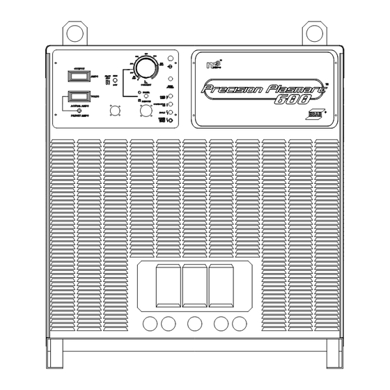
Page 20: Control Panel
Indicator illuminates when a serious fault is detected. Input power must be disconnected for at least 5 seconds and then reapplied. F - Current Dial (Potentiometer) EPP-600 dial shown. EPP-600 has a range of 12 to 600 A. Used only in panel mode. - Page 21 LOW is used. This can vary depending on gas, material and torch used. High/Low settings are specified in cutting data included in the torch manual. When the EPP-600 is set to marking mode, this switch must be in the low position.
- Page 22 sectIon 4 operatIon 4.2 control panel (con’t.) J - Meters Displays voltage and amperage when cutting. The ammeter can be activated when not cutting to view an estimation of the cutting current before cutting begins. K - Actual/Preset Switch The ACTUAL AMPS / PRESET AMPS spring return toggle switch, S42, defaults to the ACTUAL (UP) position.
- Page 23 7.50VDC. For signals over 8.00V, the power source internally limits the output current to a typical value of 680A. The EPP-600 defaults to the Cutting Mode of operation unless the command signal for Marking Mode is supplied. The power source is placed in Marking Mode with an external isolated relay or switch contact connecting J1-F (115VAC) to J6-A.
-
Page 24: Sequence Of Operation
4.3 sequence of operation 4.3 Sequence of Operation Apply power by closing the line (wall) switch. (The EPP-600 Apply Power does not have an on / off switch). The main power light will illuminate and the fault light will flash and then go out. -
Page 25: Electric Shock Can Kill
The time to achieve full current can be adjusted for a soft start. This feature uses a reduced current to start and then gradu- ally ramps up to full current. The EPP-600 is factory shipped with soft start enabled. The default settings are: Minimum Start Current . - Page 26 sectIon 4 operatIon 4.4.1 enable/Disable arc Initiation conditions Factory default setting shown. 1. Remove access panel on the upper-right corner of the front panel. Be sure to replace this panel after adjustments have been made. 2. Locate SW1 and PCB1 and push both rocker switches down to disable. To enable push both switches up. (If one switch is up and the other is down, arc initiation time is considered on.) 4.4.2 adjusting arc Initiation timer Factory default settings shown...
-
Page 27: Arc Initiation Controls
sectIon 4 operatIon 4.4.3 arc Initiation controls Start Current Potentiometer UP-Slope Timer 4.4.4 start current and up-slope timer Starting Current (%) and Pot Setting Relationship Start Current Set using potentiometer located above and to the left of center of PCB1. Factory default setting of 7 results in a starting current that is 50% of the cutting current.. -
Page 28: Epp-600 V-I Curves
4 operatIon 4.5 epp-600 v-I curves OUTPUT VOLTAGE (Volts) Output Voltage (volts) MIN MARK RATING Min. Marking Current = 0.150V = 0.150V Min. Cutting Current MIN CUT RATING = 0.625V = 0.625V = 1.000V = 1.000V = 2.000V = 2.000V = 3.000V...
Need help?
Do you have a question about the epp-600 and is the answer not in the manual?
Questions and answers