Advertisement
Quick Links
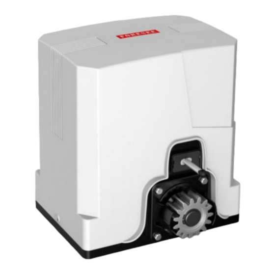
F550/F560
F550/F560
Specifications
Supply
220-240Vac 50Hz 2.5A
Pinion
Mod.4 15 teeth
Speed
16mm/sec
Duty cycle
25% 20 times/hr
F550 – 600kg
Gate size
F560 – 900kg
F550 – 110W
Motor power
F560 – 150W
Temp O/L
120°C
Temp'
-20°C to 50°C
Protection
IP44
Description
The F550 & F560 sets are based around the PICO 24Vdc sliding
gate motors. The F550 is for domestic gates. The F560 is for
light industrial gate applications such as an office development.
A toothed rack fixed to the gate engages with a pinion on the
motor. Drive is delivered through a worm drive gearbox. The gate
cannot be moved while the gearbox is engaged. A key override
disengages the motor from the drive pinion. Used in exceptional
circumstances, like power failure.
Two double button rolling code remotes are included. Buttons can
be programmed to open fully for vehicles or partial opening for
pedestrians. The 2
nd
button can open another gate. Up to 16
remotes can be registered. A safety photo beam is included to
detect vehicles. Further safety devices may be added.
Operation
On an input from a remote or an external control, the gate will
open fully or partially. The closed and fully open positions are
determined by limit switches acting on 'skis' fitted to the rack. If
the remote is activated while the gate is running, it will stop. The
next remote activation will re-start in the other direction.
For safety, the gate slows at ends of travel. If the automatic
close function is enabled, the gate will re-close after a delay.
If the photo beam is interrupted during closing, the gate stops
then re-opens. The gate will stay open while the beam is
interrupted. The motor has a stall sensor to detect physical
blocks in the gates path. If an obstacle is detected in either
direction, the gate will stop and reverse direction.
Safety warnings
Automatic gates can be hazardous. It is the responsibility
of the home owner to be aware of the risks and provide,
adequate warning of hazards. Users should be given instruction on
the safe use of the automatic gate.
This manual is written for engineers aware of construction criteria for
automatic gates and accident prevention criteria in force in the
automation industry. Only qualified persons may do installation or
maintain work on this barrier that may change its risk assessment.
Turn off the power before working on the gate. We recommended
signage to warn users and members of the public of risk of injury to
pedestrians. Do not permit public access to the gate area. Do not use
remotes when out of sight of the gate. Do not let children or untrained
people use remotes. Do not let unsupervised children near the gate.
PICO installation manual
Photobeam
Physical Protection
Gates must be of a robust construction to be automated without
attendance. Wheels on which the gate roll must be free running &
well maintained on clean level ground tracks. Support rollers must
be adjusted and maintained for smooth running. Gates must have
physical stops at both extremes to prevent derailment hazards.
Cables must be sufficiently protected against abrasion that could
lead to a hazard due to exposure of electrical conductors.
Electrical supplies must be protected by an earth leakage device.
There must a disconnect switch outside the gate area.
'Automatic gate' signs are required on both sides of the gate
warning against risk of contact injury. A pedestrian side gate is
preferred for regular pedestrian access.
User Instructions
It is the site owner or manager's responsibility to ensure that only
trained people operate the gate, and ensure all operators are
aware of gate hazards. Operators must take responsibility for the
safety of any person within the hazard area. Never let children
play near gates in motion.
Keep the gate area clear of objects. Examine the gate for
imbalance or signs of wear. Have gate properly maintained and
repaired by qualified personnel when necessary.
Manufacturers are not responsible for injury resulting from failure
to meet the requirements in this manual. An adequate clearance
must be provided around the gate to prevent entrapment.
B05
doc.
doc.
Description
User notices
Safety warnings
Warranty
Site preparation
Alignment
Motor & rack
Ducts & Cabling
Setup
Quick setup
Connections
DIP switches
Adjustment
Remotes
Wiring
Universal wiring
Examples
Certificate of conformity
Warranty
Remotes
B05
P1
iss V1.1
1
2
3
4
Advertisement

Related Manuals for Forematic F550


Summary of Contents for Forematic F550
- Page 1 Certificate of conformity Description Warranty The F550 & F560 sets are based around the PICO 24Vdc sliding gate motors. The F550 is for domestic gates. The F560 is for light industrial gate applications such as an office development. Photobeam...
- Page 2 F550/F560 SITE PREPARATION doc. Mechanical Near post Gates must be level and free running on a ground track, or on cantilever gate bearings. It is usual to Far post support the gate at the top with nylon rollers. Two gates mounted on the same track may slide from each side of an opening to meet in the centre.
- Page 3 F550/F560 SETUP doc. 1. Quick setup Motor must be engaged with the rack and skis set for short travel. Connect Mains supply to L & N terminals on power board. Connect together terminals IR, Stop & Gnd. Set all DIP switches down. Set LV, RV, Force anti-clockwise Hold down ST button for 5 secs until DL5 lights.
-
Page 4: Declaration Of Conformity
Machinery Directive with amending directives 2006/95/EC LV Directive 2004/108/EEC EMC Directive 1999/5/EC R&TTE Directive 23.03.2011 – FOREMATIC 9 Vanalloys Estate, Stoke Row, Mr H WYNN JONES Henley RG9 5QW, United Kingdom Director WARRANTY Forematic 3 year return to base warranty covers defective manufacture and material. The warranty does not cover accidental damage, misuse, or abnormal wear.
Need help?
Do you have a question about the F550 and is the answer not in the manual?
Questions and answers