
Related Manuals for Husqvarna AR19


Summary of Contents for Husqvarna AR19
- Page 1 Operator´s manual AR19 AR25 Please read these instructions carefully and make sure English you understand them before using the machine.
-
Page 3: Table Of Contents
TABLE OF CONTENTS Operator’s Manual for Lawn Aerator AR19, AR25 Introduction ............2 Replacing the air filter ........25 Congratulations ..........2 Cleaning the sludge reservoir ......26 Use ..............2 Idle adjustment ..........26 Insure your machine ......... 2 Adjusting the throttle cable ...... -
Page 4: Introduction
INTRODUCTION Congratulations Thank you for purchasing a Husqvarna lawn care product. Through your confidence in us, you have chosen an exceptionally high quality product. This manual is a valuable document. It describes your new Husqvarna machine. Read the manual carefully before attempting to use the machine. -
Page 5: What Is Aeration
INTRODUCTION What is aeration? For your lawn to grow at its best, the roots need to be surrounded by air pockets in the soil so that oxygen, water and nutrients can be absorbed. Air pockets in the lawn shrink as the earth is compacted by pedestrian traffic, rainfall, irrigation, or construction and landscaping work. -
Page 6: Symbols And Decals
Used also when there is a potential for misuse or misassembly. Decals and machine-bound instructions 8011-236 A. Model designation AR19 G. WARNING carbon monoxide B. Weights H. Husqvarna logotype C. Wheel removal (AR25) DANGER Mind your feet D1. -
Page 7: Location Of Decals
SYMBOLS AND DECALS Location of decals 8011-237 Translation of instructions Decal E Decal G Important information Warning Read and make sure you understand the Operator’s Engine exhaust, some of its constituents and Manual before use or maintenance. certain vehicle components contain or emit chemicals considered by the State of California to To obtain a replacement manual, please contact your cause cancer, birth defects or other reproductive... -
Page 8: Safety Instructions
SAFETY INSTRUCTIONS General WARNING! The object of this manual is to help you use your Husqvarna machine more safely and to give you Under no circumstances may the information about how to maintain your machine. original design of the machine be... -
Page 9: Children
• Never leave the machine unsupervised with the engine running. • Husqvarna original spare parts are designed and specified to maintain high quality and correct fit for optimal durability and lifespan. From a safety point of view, you should only use Husqvarna original spare parts. -
Page 10: Preparations
Protective clothing and protective equipment cannot eliminate the risk of accidents but wearing proper clothing and the correct equipment will reduce the degree of injury should an accident occur. Ask your dealer about approved protective clothing and approved protective equipment recommended by Husqvarna. 8 – English... -
Page 11: Running
SAFETY INSTRUCTIONS Running WARNING! The engine can become very hot. To avoid being burned, you must turn off the engine and wait until all parts have cooled before touching the engine. • Do not use the machine on grades of more than 20°. -
Page 12: Movement/Transport
SAFETY INSTRUCTIONS • Smoking, open flames or sparks in the vicinity of the machine are strictly forbidden. Gasoline is extremely flammable and can result in personal injury or fire. • Stop and inspect the equipment if you run over or into anything. If necessary, make repairs before beginning again. -
Page 13: Fuel System
SAFETY INSTRUCTIONS Fuel system WARNING! Gasoline and gasoline fumes are poisonous and extremely flammable. Be especially careful when handling gasoline, as carelessness can result in personal injury or fire. • Only store fuel in containers approved for the purpose. • Never remove the fuel cap and fill the fuel tank while the engine is running. -
Page 14: Maintenance
SAFETY INSTRUCTIONS Maintenance • Never allow persons not trained in the use of the machine to perform service on it. • Always park the machine on even ground before performing maintenance or making adjustments. • Never make adjustments with the engine running. -
Page 15: Presentation
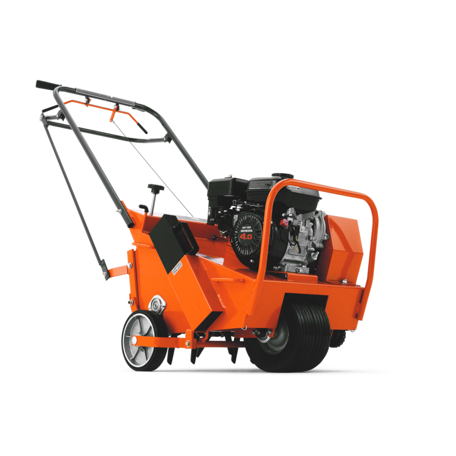
AR19 and AR25. Both machines are equipped with a 4 hp Honda four- cycle engine. AR19 is the smaller of the two machines (see illustration). It is recognizable for its collapsible handle. AR25 is broader and has a fixed handle. -
Page 16: Engine
PRESENTATION Engine Exterior engine components and operating instruments: Throttle Starter Starter handle Fuel valve Choke control Air filter Spark plug Muffler 8011-043 11. Oil dipstick engine 12. Oil drainage engine 13. Oil level guard 14. Engine switch 15. Fuel tank 16. - Page 17 PRESENTATION Starter The starter is of the magnapull type with spring return. To replace the return spring or starter cord, contact an authorized service workshop. Starter handle Misuse of the starter handle can damage the starter. Never twist the starter cord around your hand. Pull out the handle slowly until the gears mesh.
- Page 18 PRESENTATION Spark plug The engine spark plug is hidden under the ignition cable shoe. When performing service, it is important that the engine cannot start accidentally. For this reason, always remove the ignition cable shoe from the spark plug. To avoid pulling the cable, the cable shoe is equipped with a special handle;...
- Page 19 PRESENTATION Fuel tank Underneath the tank, there is a fuel filter combined with the fuel valve. The tank volume is 2.5 liters/ 0.66 US Gal. Fueling Read the safety instructions before fueling. Keep the fuel and fuel tank clean. Avoid filling the machine with dirty fuel.
-
Page 20: Controls On The Handle
PRESENTATION Controls on the handle Rear wheel control Pressing down the rear wheel control raises both rear wheels causing the tines to penetrate into the soil. 8011-086 Clutch handle Depressing the spring-loaded clutch handle towards you causes the machine to begin moving. 8011-087 Cam lock for the handle If the lever for the handle locking mechanism is... -
Page 21: Adjusting The Rear Wheels
PRESENTATION Adjusting the rear wheels You can improve stability and maneuverability by turning the knob for the rear wheel depth/stability clockwise (see illustration). Turning the knob counterclockwise determines aeration depth in the following ways: (A) The rear wheels can be adjusted to the level of your choice so that you can control the penetration of the tines to a margin of a few millimeters. -
Page 22: Running
RUNNING Starting the engine Check that all daily maintenance as described in the maintenance schedule has been performed. Check that there is sufficient fuel in the tank. Fuel valve Open the fuel valve. Turn the lever all the way to the right. -
Page 23: Cutting The Engine
RUNNING Throttle Adjust the engine speed with the throttle. Moving the lever to the left increases throttle and to the right decreases throttle. For machines with a throttle on the handle, the throttle on the engine should be set at idle position. 8011-034 Cutting the engine If the engine has been running full out, let it run... -
Page 24: Aeration Tips
Make sure that the collapsible handle is in IMPORTANT INFORMATION working position and locked in place with the cam lock (applies to model AR19). Clear the lawn of any extraneous objects. Clearly mark rocks and other fixed objects. Fit the weights if necessary. -
Page 25: Turning And Maneuvering The Lawn Aerator
RUNNING Turning and maneuvering the lawn aerator IMPORTANT INFORMATION You maneuver the machine by gradually controlling Never run over hard objects or surfaces the direction with the handle while operating the lawn (walkways, driveways, paved surfaces, etc.) aerator. We recommend setting engine speed so that with the tines down. -
Page 26: Maintenance
MAINTENANCE Maintenance schedule The following is a list of maintenance procedures that must be performed on the machine. For those points not described in this manual, visit an authorized service workshop. Daily Maintenance interval months/hours maint. Maintenance Page before 1/25 3/50 6/100 12/300... -
Page 27: Replacing The Air Filter
MAINTENANCE Replacing the air filter If the engine seems weak, produces black smoke or runs unevenly, the air filter may be clogged. For this reason, it is important to clean and replace the air filter regularly (see the maintenance schedule for the proper service interval). -
Page 28: Cleaning The Sludge Reservoir
MAINTENANCE Cleaning the sludge reservoir Close the fuel valve. 8011-036 Unscrew the sludge reservoir (2). Make sure not to misplace the o-ring (1). Clean the reservoir and the o-ring in e.g. white spirit and dry carefully. Put the o-ring in place in its track and replace the sludge reservoir. -
Page 29: Adjusting The Throttle Cable
MAINTENANCE Adjusting the throttle cable Only applies to model AR25. Start the engine and allow it to reach operating temperature. Adjust the throttle cable at the adjustable mounting (the left in the illustration) by turning the adjustment nut. The tighter the setting, the higher the engine speed. -
Page 30: Ignition System
MAINTENANCE Ignition system The engine is equipped with an electronic ignition system. Only the spark plug requires maintenance. For recommended spark plug, see ”Technical data”. IMPORTANT INFORMATION Fitting the wrong spark plug type can damage the engine. Remove the ignition cable shoe and clean around the spark plug. -
Page 31: Replacing The Engine
MAINTENANCE Replacing the engine Remove the weights to improve access. Remove the drive guard cover (1). Remove the drive belt. Remove the four engine screws (2). Two on each side. Remove the engine from the unit. IMPORTANT INFORMATION Lawn aerators of model AR25 have two pairs 8011-218 of shim plates under the engine. -
Page 32: Replacing And Adjusting The Drive Belt
Check that the lawn aerator rolls freely (with the handle collapsed on model AR19) when the drive belt is slack. Adjust the belt guide and the clutch cable length as necessary. -
Page 33: Cam Lock For The Handle
MAINTENANCE Cam lock for the handle Only applies to model AR19. The cam lock (3) on the handle should lock if you press it with moderate force using your hand. The frame of handle (2) should be properly affixed to the machine. -
Page 34: Wheels
Secure the handle so that the lawn aerator cannot tip over. Remove the nuts (1) and screws (2) (4 of each on model AR19 and 6 on model AR 25) for the wheel axle bearings. Remove the wheel axle with wheels and sprocket. - Page 35 MAINTENANCE Replacing the rear wheels Applies to model AR19. Make sure the machine is parked on level ground and that the engine is off. Lower the rear wheel control so that the lawn aerator is resting on the tines. Turn the depth adjustment knob for rear wheel...
-
Page 36: Tines And Tine Shaft
Tines and tine shaft Replacing the tines Turn off the engine and remove the weights. Collapse the handle (applies to model AR19). Note the direction of the tine screw. Remove and replace the tines by undoing the appropriate stop screw (1). Remove the setscrew (2) and the tine. - Page 37 Replacing the freewheeling tine assembly 8011-171 Model AR19 has one freewheeling tine assembly at each side but model AR25 has two. The illustration above shows model AR25. Perform steps 1 through 10 in the previous section ”Replacing the tine shaft bearings” and then the following:...
-
Page 38: Chain
(4) and the rotor sprocket on the tine shaft assembly. See the illustration for the dimension (3). Tighten the locking nut (2). IMPORTANT INFORMATION Husqvarna recommends replacing the 8011-074 sprockets at the same time as the drive chain. 36 – English... -
Page 39: Cleaning And Washing
MAINTENANCE Cleaning and washing Regular cleaning, washing and lubrication will increase the machine’s lifespan. Make it a habit to clean the machine directly after use, before the dirt sticks. Check before rinsing that the fuel tank lid is properly in place to avoid getting water in the tank. Use caution when using high-pressure spray because warning decals, instruction signs, bearings, the chain and the engine can be damaged. -
Page 40: Lubrication
LUBRICATION Lubrication schedule 8011-280 38 – English... -
Page 41: General
General Stop the engine and remove the ignition cable before attempting to lubricate the machine. Unless otherwise specified, when lubricating with grease use Husqvarna’s Universal Grease no. 5310038-01 or Husqvarna’s Lubrication Grease UL 21 no. 5310060-74. Wipe away excess grease after lubrication. -
Page 42: Oil Change In Reduction Gear 1:6
LUBRICATION Checking the engine’s oil level. Make sure that the machine is parked on even ground with the engine stopped when checking the oil level. Unscrew the dipstick and wipe it using paper towel or a lint-free rag. Replace the dipstick without screwing it in. Remove and check the level on the dipstick. -
Page 43: Chain
8011-132 4. Rear wheels Applies to model AR19. Lubricate both rear wheels with a grease gun in the single nipple on the outside of the rear wheels until the grease begins to squeeze out. -
Page 44: Adjustment For Rear Wheel Depth/Stability
LUBRICATION 7. Adjustment for rear wheel depth/stability Lubricate the threads regularly with grease to avoid binding or locking. It is particularly important to lubricate the threads after cleaning. 8011-271 8. Cam lock for the handle Lubricate the edge of the cam with a little grease. 8011-088 9. -
Page 45: Assembly Instructions
ASSEMBLY INSTRUCTIONS Assembly – Initial start-up Applies to model AR19. IMPORTANT INFORMATION Use eye protection. Remove the wooden blocks. Be careful for nails and slivers. Carefully cut along the side of the box. The lawn aerator is delivered with the handle collapsed. - Page 46 ASSEMBLY INSTRUCTIONS Applies to model AR25. Use eye protection. Remove the wooden blocks. IMPORTANT INFORMATION Be careful for nails and slivers. Carefully cut along the side of the box. The lawn aerator is delivered with the handle removed. Fit the handle using two wrenches (13 mm).
-
Page 47: Storage
”Lubrication/ Lubrication schedule”. Always use genuine Husqvarna spare parts. Store the machine in a clean, dry place and An annual check-up at an authorized service cover it for extra protection. -
Page 48: Wiring Diagram
WIRING DIAGRAM 8011-099 8011-050 Legend for color abbreviations in wiring diagram 1. Engine switch RD = Red 2. Transistor ignition unit SV = Black 3. Spark plug GL = Yellow 4. Oil level guard 46 – English... -
Page 49: Troubleshooting
TROUBLESHOOTING Symptom Cause Action The engine will not start • User error Fuel valve closed. Open the fuel valve. Choke valve open. Close the choke with cold engine. Engine switch in OFF position. Turn the engine switch to ON. • Fuel system Fuel tank empty. -
Page 50: Technical Data
TECHNICAL DATA Engine unit AR19 AR25 Engine Honda GX120 Honda GX120 Cylinder volume 119 cm (7.3 cu in) 119 cm (7.3 cu in) Power 4 hp (3 kW) at 3600 RPM 4 hp (3 kW) at 3600 RPM Torque 7.4 Nm at 2500 RPM 7.4 Nm at 2500 RPM... -
Page 51: Service Journal
SERVICE JOURNAL Action Date, stamp, signature Delivery service Break the packaging and make sure the machine has not been damaged in transport. Where applicable, assembly accompanying components. Check that the machine design corresponds to the customer order. Check that the right amount of oil is in the engine and transmission. - Page 52 SERVICE JOURNAL Action Date, stamp, signature ○ ○ ○ ○ ○ ○ ○ ○ ○ ○ ○ ○ ○ ○ ○ ○ ○ ○ ○ ○ ○ ○ ○ ○ ○ ○ ○ ○ ○ ○ ○ ○ ○ ○ ○...
- Page 53 SERVICE JOURNAL Action Date, stamp, signature ○ ○ ○ ○ ○ ○ ○ ○ ○ ○ ○ ○ ○ ○ ○ ○ ○ ○ ○ ○ ○ ○ ○ ○ ○ ○ ○ ○ ○ ○ ○ ○ ○ ○ ○...
- Page 54 SERVICE JOURNAL Date, stamp, signature Action ○ ○ ○ ○ ○ ○ ○ ○ ○ ○ ○ ○ ○ ○ ○ ○ ○ ○ ○ ○ ○ ○ ○ ○ ○ ○ ○ ○ ○ ○ ○ ○ ○ ○ ○...
- Page 55 8011-156 8011-157 8011-159 8011-158...
- Page 56 114 00 28-26 ´+H"r¶6=¨ 2001W35...
Need help?
Do you have a question about the AR19 and is the answer not in the manual?
Questions and answers