Table of Contents
Advertisement
Advertisement
Table of Contents

Subscribe to Our Youtube Channel
Related Manuals for Indian Motorcycle Chief Classic


Summary of Contents for Indian Motorcycle Chief Classic
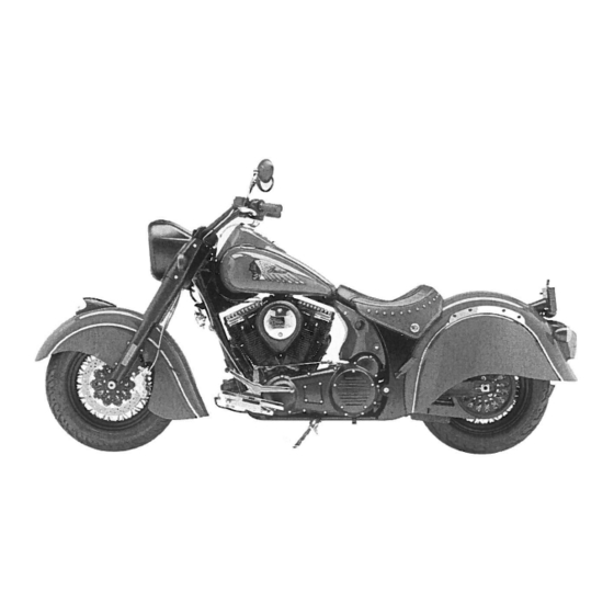
- Page 1 2014 RIDER’S MANUAL ® Indi Chief Cla ic ® Indi Chief Vintage ™ Indi Chieftain...
- Page 2 California Proposition 65 Warning This product contains or emits chemicals known to the state of California to cause cancer and birth defects or other reproductive harm.
- Page 3 2014 Rider’s Manual ® Indian Chief Classic ® Indian Chief Vintage Indian Chieftain™...
- Page 4 No liability can be accepted for omissions or inaccuracies. Indian Motorcycle Company reserves the right to make changes at any time, without notice and without incurring obligation to make the same or similar changes to motorcycles previously built. Any reprinting or reuse of the depictions and/or procedures contained within, whether whole or in part, is expressly prohibited.
-
Page 5: Table Of Contents
Table of Contents Introduction ......4 Safety ......5 Reporting Safety Defects . -
Page 6: Introduction
Some procedures are beyond the scope of this manual. See riders who have acquired a celebrated piece of American your dealer to purchase an INDIAN MOTORCYCLE Service history by choosing to own an INDIAN motorcycle. Manual. Some procedures provided in the service manual Your new motorcycle is the end result of true dedication and require specialized knowledge, equipment, and training. -
Page 7: Safety
WARNING manual, please see your authorized dealer. To locate the A WARNING indicates a hazardous situation that, if not avoided, could nearest authorized INDIAN MOTORCYCLE dealer, visit the result in death or serious injury. INDIAN MOTORCYCLE web site at www.indianmotorcycle.com. -
Page 8: Safe Riding Practices
This section contains safety information specific to the INDIAN motorcycle, as well as information about general motorcycle safety. Anyone who rides the motorcycle (operators and passengers) must follow these safety precautions. - Page 9 They can also affect your awareness and judgment. • If your motorcycle operates abnormally, correct the problem immediately. See the INDIAN MOTORCYCLE Service Manual or an authorized INDIAN MOTORCYCLE dealer.
- Page 10 Safety Safe Riding Practices • Reduce speed when: • Retract the sidestand fully before riding. If the sidestand is not fully retracted, it could contact the road surface and - The road has potholes or is otherwise rough or uneven. cause loss of control.
-
Page 11: Carrying A Passenger
Safety Safe Riding Practices Carrying a Passenger Do not carry a passenger unless the motorcycle is equipped with passenger seat and passenger footrests. To carry a passenger safely: • Do not exceed the gross vehicle weight rating (GVWR) for • Before riding, be sure your passenger knows safe riding your motorcycle. -
Page 12: Protective Apparel
Safety Safe Riding Practices Protective Apparel Wear protective apparel to decrease the risk of injury and increase riding comfort. • Always wear a helmet that meets or exceeds established • All riders should wear bright or light-colored and/or safety standards. Approved helmets in the USA and reflective clothing to improve visibility to other motorists. - Page 13 Safety Use of Accessories Because INDIAN MOTORYCLE cannot test and make • Do not install electrical accessories that exceed the specific recommendations concerning every accessory or capacity of the motorcycle’s electrical system. Never combination of accessories sold, the operator is responsible install higher wattage light bulbs than those supplied as for determining that the motorcycle can be safely operated original equipment.
-
Page 14: Parking The Motorcycle
Some modifications may not be legal in your • Distribute weight evenly on each side of the motorcycle. area of operation. If in doubt, contact your authorized INDIAN MOTORCYCLE dealer. • Do not exceed the individual weight limit of each saddlebag. - Page 15 Safety Carrying Cargo Use the following guidelines when attaching cargo or accessories to the motorcycle. Where applicable, these guidelines also refer to the contents of any accessories. • Keep cargo and accessory weight to a minimum, and • Do not attach large or heavy cargo such as sleeping bags, keep items as close to the motorcycle as possible to duffel bags or tents to the handlebars, front fork area or minimize a change in the motorcycle’s center of gravity.
-
Page 16: Transporting The Motorcycle
Safety Transporting the Motorcycle Fuel and Exhaust Safety If you must transport the motorcycle: Always heed these fuel safety warnings when refueling or servicing the fuel system. For fueling procedures, see page • Use a truck or trailer. Do not tow the motorcycle with another vehicle, as towing will impair the motorcycle's steering and handling. -
Page 17: Electromagnetic Interference
Failure to perform safety maintenance as recommended can result in difficult handling and loss of control, which could result in serious injury or death. Always perform the safety maintenance procedures as recommended in this manual. Perform maintenance and repairs promptly. See the INDIAN MOTORCYCLE Service Manual or an authorized INDIAN MOTORCYCLE dealer. • Before each ride, perform the Pre-Ride Inspections. See •... -
Page 18: Reporting Safety Defects
Refer to the Specifications section of this manual (page 124) individual problems between you, your INDIAN or the Manufacturing Information/VIN label on the MOTORCYCLE dealer or Indian Motorcycle Company. motorcycle frame for model-specific information. To contact NHTSA, or obtain other information about motor... - Page 19 Safety Safety and Information Labels Labels are model-specific and market-specific. Your motorcycle may not contain all of the labels shown. 1. Vehicle Identification Number (VIN) (on side of steering head) 2. Vehicle Emission Control Information (VECI) 6. Highway Bar Warning 3.
-
Page 20: Component Identification
Component Identification 1. Rear Brake Pedal CHIFTAIN shown 2. Right Front Turn Signal 3. Windshield (if equipped) 4. Auxiliary Lights 5. Left Front Turn Signal 6. Headlight 7. INDIAN MOTORYCLE War Bonnet 8. Passenger’s Foot Peg 9. Driver’s Footrest 10. Gear Shifter 11. - Page 21 Component Identification CHIEFTAIN shown...
-
Page 22: Engine Identification Number
Component Identification Engine Identification Number The engine number is stamped into the right crankcase beneath the balance shaft cover. The engine number is positioned behind the right floorboard with the engine installed in the frame. Record the number in the space provided on page 129. - Page 23 Component Identification Console 1. Clutch Lever 2. Fuel Gauge (CHIEF) 7. Front Brake Lever 3. Instrument Cluster 8. 12-Volt Outlet (CHIEFTAIN) 4. Power Switch/Security Light 9. Fuel Cap 5. Front Brake Master Cylinder 10. Ornamental Cap (Do not remove) 6. Throttle Control Grip CHIEF CHIEFTAIN...
-
Page 24: Instruments, Features & Controls
Instruments, Features and Controls Switches Engine Flasher (Hazard) Stop/Run High/Low Switch Left Control Right Control Light Switch Switch Turn Signal Switch Horn Engine Cruise Switch Starter Control Switch Switch Cruise CHIEFTAIN On/Off Windshield CHIEFTAIN Audio Switch Switches Control Switches RIGHT-TOGGLE Switch Left Control LEFT-TOGGLE Switch Right Control... - Page 25 Instruments, Features and Controls Switches CHIEF CHIEFTAIN Auxiliary Power Switch Auxiliary Light Switch Light Switch Power Switch Saddlebag Lock Switch...
- Page 26 Instruments, Features and Controls Switches Symbol Switch Description Emergency Flasher The hazard switch activates and cancels the emergency flashers. See page 25. Switch (Hazard Switch) High/Low Headlight The high/low headlight beam switch toggles the headlight between high beam and low beam. See page Beam Switch Auxiliary Light auxiliary...
-
Page 27: Hazard Switch
Instruments, Features and Controls Switches Power Switch Engine Stop/Run Switch The power switch is attached to the fuel tanks on the center Use the engine stop/run switch console. Press and release the power switch to enable or to turn the engine off quickly. Stop disable all electrical power to the vehicle. - Page 28 Instruments, Features and Controls Switches Engine Starter Switch Saddlebag Lock Switch Read the engine starting If your model is equipped with electric saddlebag locks, the procedures before starting the locks can be controlled by either the key fob or the lock engine.
- Page 29 Instruments, Features and Controls Switches Ignition/Light Switch High/Low Headlight Beam Switch The headlights automatically come on when the engine is The high/low headlight beam switch toggles the headlight started. between high beam and low beam. To activate the high beam, press the upper portion of the switch. To activate the WARNING! Motorcycle riders must remain as visible as possible at low beam, press the lower portion of the switch.
- Page 30 Instruments, Features and Controls Instrument Cluster (CHIEF) Indicator Lamps The instrument cluster includes the speedometer, indicator lamps and Multi-Function Display (MFD). Lamp Indicates Condition Speedometer Indicator Lamps Turn The turn signal indicator flashes when the left, Signal right, or both turn signals (hazard) are active. If there is a problem in the signal system, the lamps will flash at twice the normal rate.
- Page 31 Instruments, Features and Controls Instrument Cluster (CHIEF) Multi-Function Display (MFD) The power switch must be ON to access the MFD. Use the Trip Odometers mode switches to toggle through the modes of the multi- The trip odometers (Trip 1 and Trip 2) display total distance function display and to change settings in the display.
- Page 32 Instruments, Features and Controls Instrument Cluster (CHIEF) Multi-Function Display (MFD) Display Units (Standard/Metric) Clock Tip: The clock must be reset any time the battery has been The display can be changed to display either standard or disconnected or discharged. metric units of measurement. 1.
- Page 33 Instruments, Features and Controls Instrument Cluster (CHIEF) Multi-Function Display (MFD) Diagnostic Functionality Certain conditions will cause an error message to display in the screen. If this occurs, please see your authorized dealer. Message Location Indicates DC Voltage Screen Voltage remains below 11.0 volts for more than 10 seconds DC Voltage Screen Voltage remains above 15.0 volts for more than 10 seconds ERROR...
- Page 34 Instruments, Features and Controls Instrument Cluster (CHIEF) Multi-Function Display (MFD) Low Oil Pressure Display “LO OIL” displays under the following conditions. Condition Indicates Action Required Engine oil pressure Oil pressure is below a Stop the engine as soon as safely possible has dropped while the safe operating pressure.
- Page 35 Instruments, Features and Controls Instrument Cluster (CHIEFTAIN) Speedometer The instrument cluster includes the speedometer, tachometer, fuel gauge, indicator lamps and multi-function The speedometer displays forward vehicle speed in either display (MFD). miles per hour or kilometers per hour. Tachometer Indicator Lamps Speedometer The tachometer displays engine speed in revolutions per Tachometer...
-
Page 36: Indicator Lamps
Instruments, Features and Controls Instrument Cluster (CHIEFTAIN) Indicator Lamps Lamp Indicates Condition Neutral The transmission is in neutral and the power switch is ON. When standard mode is selected, speed displays in miles per hour. Vehicle Speed When metric mode is selected, speed displays in kilometers per hour. High Beam The headlight switch is set to high beam. - Page 37 Instruments, Features and Controls Instrument Cluster (CHIEFTAIN) Indicator Lamps Lamp Indicates Condition Low Battery This lamp illuminates when battery voltage is low. Turn non-essential accessories off to conserve power. Make Voltage sure the charging system is operating properly. See page 119. This lamp also illuminates with the security light and/or power switch when the key fob battery is low, and with the TPMS lamp when the TPMS sensor battery is low.
- Page 38 Instruments, Features and Controls Instrument Cluster (CHIEFTAIN) Multi-Function Display (MFD) Infotainment Display The power switch must be on or the engine must be running There are four zones in the to view or change settings in the MFD. Use the LEFT- center display.
- Page 39 Instruments, Features and Controls Instrument Cluster (CHIEFTAIN) Zone Three Information The following items can be displayed in Zone Three on the Trip 1 Hours/Distance infotainment display: Trip 1 Hours/Distance will display the total hours and distance in miles or • Trip 1 Hours/Distance kilometers.
- Page 40 Instruments, Features and Controls Instrument Cluster (CHIEFTAIN) Zone Three Information Fuel Economy Engine Hours/Oil Life This screen will display the current This screen will display the total instant and average miles per gallon engine hours accumulated when the (MPG) or liters per 100 kilometers. engine is running.
- Page 41 Instruments, Features and Controls Instrument Cluster (CHIEFTAIN) Zone Three Information Average Speed/Battery Voltage Heated Grips (if equipped) This screen displays the average If heated grips are installed on the motorcycle speed and current battery motorcycle, the Heated Grips display voltage. will show the current heated grip power level setting.
- Page 42 Instruments, Features and Controls Instrument (CHIEFTAIN) Zone Three Information Diagnostic Trouble Codes (DTCs) Retrieving Error Codes If the CHECK ENGINE indicator is If the CHECK ENGINE indicator illuminates, you can retrieve illuminated on the instrument cluster, the error codes from the DTC display. this screen will display, indicating LEFT-TOGGLE 1.
- Page 43 Instruments, Features and Controls Instrument Cluster (CHIEFTAIN) Instrument Cluster Setup The instrument cluster setup menus allow the following Setting the Clock actions: 1. With SET CLOCK highlighted on the setup menu, press LEFT- • Set clock TOGGLE • Set units (volume, temperature, clock LEFT-TOGGLE type, pressure) 2.
- Page 44 Instruments, Features and Controls Instrument Cluster (CHIEFTAIN) Instrument Cluster Setup Set Units Set Units - Distance Setting Use the SET UNITS menu to set the Use the DISTANCE menu to change following items: the speedometer and distance units. Select either miles or •...
- Page 45 Instruments, Features and Controls Instrument Cluster (CHIEFTAIN) Instrument Cluster Setup Set Units - Volume Settings Set Units - Temperature Settings Use the VOLUME menu to change Use the TEMPERATURE menu to the instrument cluster volume change the instrument cluster units. Select gallon, imperial gallon temperature units.
- Page 46 Instruments, Features and Controls Instrument Cluster (CHIEFTAIN) Instrument Cluster Setup Set Units - Clock Type Set Units - Pressure Use the CLOCK TYPE menu to Use the PRESSURE menu to change change the clock format. Select 12- the pressure display format. Select hour or 24-hour format.
- Page 47 Instruments, Features and Controls Instrument Cluster (CHIEFTAIN) Instrument Cluster Setup Set Bottom Screen Menu Trip 1 Distance Display Use the SET BOTTOM SCREEN menu to display one of the following items in ZONE FOUR of the display screen: • Trip 1 Distance Instant Fuel Display •...
- Page 48 System (TPMS) Setup The instrument cluster hardware and software part and serial The TPMS setup menu allows your numbers are displayed on the authorized INDIAN MOTORCYCLE Gauge Information menu. dealer to register new tire pressure sensors. 1. With GAUGE INFORMATION...
- Page 49 Instruments, Features and Controls Instrument Cluster (CHIEFTAIN) Instrument Cluster Setup Set Brightness METHOD 2: 1. With SET BRIGHTNESS The brightness level of the instrument cluster and display highlighted on the setup menu, screen can be adjusted. There are two methods to enter the LEFT-TOGGLE press Set Brightness menu.
-
Page 50: Throttle Control Grip
Instruments, Features and Controls Throttle Control Grip Clutch Lever The throttle control grip is The clutch lever is Decrease Clutch Lever Speed located on the right located on the left handlebar. Use the throttle handlebar. Disengage the control grip to control clutch before shifting engine speed. -
Page 51: Gear Shift Lever
Instruments, Features and Controls Gear Shift Lever Mirrors The gear shift lever is located on the left side of the Your vehicle is equipped with convex mirrors. Objects seen motorcycle. Operate the lever with your foot. in a mirror may be closer than they appear. Always adjust mirrors before riding. - Page 52 Instruments, Features and Controls Sidestand Saddlebags The sidestand is equipped with a safety switch that prevents Do not exceed the weight limit of each saddlebag. Always operation of the motorcycle if the sidestand is deployed. distribute weight evenly in each of the saddlebags. Hard bag capacity is 22 pounds (10 kg) of cargo per side.
- Page 53 Instruments, Features and Controls Saddlebags Hard Bag Removal 1. Unlock the electric 7. To reinstall, place the hard bag in a fully seated position saddlebag locks (if on the muffler. equipped). NOTICE: To prevent damage to components, always make sure Tip: The provided key can also be saddlebags are fully seated onto the muffler before used in the latch release buttons...
- Page 54 Instruments, Features and Controls Windshield Windshield Removal (CHIEF) (if equipped) Windshield Adjustment (CHIEFTAIN) 1. If equipped with a Use the windshield switch to adjust windshield quick-latch windshield, height for the best wind deflection. rotate the two latches • Press the top of the switch to adjust the upward.
- Page 55 Instruments, Features and Controls Brakes Anti-Lock Brake System (ABS) The anti-lock brake system automatically reduces or increases brake pressure as needed to provide optimum braking control, reducing the chance of wheel lock-up during hard braking events or when braking on rough, uneven, slippery or loose surfaces.
- Page 56 • If the lamp continues to illuminate after vehicle speed exceeds 6 MPH (10 km/h), the ABS system is not functioning. See your INDIAN MOTORCYCLE dealer promptly for service. • Operating with non-recommended tires or improper tire pressure may reduce the effectiveness of the anti-lock brake system.
- Page 57 Instruments, Features and Controls Brakes Rear Brake Pedal The front brake lever activates the front brake calipers. The rear brake pedal activates the rear brake caliper. For The rear brake pedal is located Rear Brake maximum brake effectiveness, apply the front brake lever on the right side of the Pedal and the rear brake pedal together.
-
Page 58: Fuel Cap
Instruments, Features and Controls Fuel Cap The fuel filler cap is located on the right side of the console. An ornamental cap is located on the left side of the console. Do not attempt to remove the ornamental cap. Ornamental Cap Fuel (Do not remove) 1. -
Page 59: Pre-Ride Inspections
• refer to the maintenance section of this manual (page 79) see your authorized INDIAN MOTORCYCLE dealer for service. • refer to the INDIAN MOTORCYCLE Service Manual WARNING! Read the entire Instruments, Features and Controls section of this manual before riding your motorcycle. - Page 60 Pre-Ride Inspections Turn the power switch on and move the stop/run switch to RUN before performing the following electrical inspections. Turn the power switch off after completing these inspections. If inspection of any electrical item reveals component failure, repair or replace the component before operating the motorcycle. Item Inspection Procedure Electrical...
- Page 61 Pre-Ride Inspections Item Inspection Procedure General Engine Oil Check the oil level. See page 60. Fuel Check the fuel level. See page 65. Fluid Leaks Check the vehicle and the ground/floor for any fuel, oil or hydraulic fluid leaks. Tires Inspect condition, pressure and tread depth.
-
Page 62: Engine Oil Level
Pre-Ride Inspections Engine Oil Level With the semi-dry sump lubrication system, the engine oil 1. Start the engine and allow it to run until it reaches level on the dipstick will fluctuate, depending on the normal operating temperature. motorcycle's position and engine speed when the engine is 2. - Page 63 If inspection reveals cuts, punctures, cracks or other result in a tire failure. Always use the correct size and type of tires specified by INDIAN MOTORCYCLE for your vehicle. Always maintain wear or damage, replace the tire before riding. Always use proper tire pressure as recommended in the rider’s manual and on...
- Page 64 Pre-Ride Inspections Front Brake Fluid Level Front Brake Lever 1. Straddle the motorcycle and bring it to the fully upright 1. Pull the front brake lever toward the handlebar and hold position. Position the handlebars so that the fluid it. The lever should move freely and smoothly. The lever reservoir is level.
- Page 65 Tighten any leaking vehicle. connections to the proper torque values and replace components as necessary. See the INDIAN MOTORCYCLE 1. Position the motorcycle on level ground in the fully Service Manual or an authorized INDIAN MOTORCYCLE upright position.
- Page 66 Pre-Ride Inspections Throttle Mechanical Clutch 1. Squeeze the clutch lever toward the handlebar and Rotate the throttle control grip. It should rotate smoothly release it. It should move freely and smoothly, and it from the rest position to the completely open position. It should return to the rest position quickly when released.
-
Page 67: Front Suspension
Pre-Ride Inspections Front Suspension Rear Drive Belt 1. Check drive belt tension. See pages 86-87. Inspect the front forks for oil leaks or damage, and verify smooth suspension operation. See page 92. Tip: The drive belt system must be cool, clean and dry to accurately measure belt tension (deflection). - Page 68 2. Move the sidestand up to the stored position and down 2. Tighten loose fasteners to the proper torque. See the to the fully extended position several times. It should INDIAN MOTORCYCLE Service Manual or an authorized move smoothly and quietly. Make sure the return spring INDIAN MOTORCYCLE dealer.
-
Page 69: Operation
Operation Engine Break-In The operation section of this manual describes how to ensure maximum performance and longevity through the The engine break-in period for your motorcycle is the first proper care and operation of your motorcycle. 500 miles (800 km) of operation. During this break-in Important areas covered by the operation section include: period, critical engine parts require special wear-in procedures so they seat and mate properly. - Page 70 Perform the break-in maintenance outlined in the maintenance section of this manual. Break-in maintenance should be performed by an authorized INDIAN MOTORCYCLE dealer. Break-in maintenance must include inspection, adjustments, fastener tightening and an engine oil and filter change. Performing break-in mainte- nance at the required odometer reading helps ensure peak engine performance, minimal exhaust emissions and maximum service life of the engine.
- Page 71 Operation Fueling Always dismount the motorcycle and refuel on level ground 3. Add fuel to the tank until it touches the bottom edge of with the sidestand down. Review the fuel warnings. See the filler neck. The tank is full at this level. page 14.
-
Page 72: Starting The Engine
Operation Starting the Engine The starter interlock system allows the engine to be started 6. Press and hold the starter switch to engage the one- only when the transmission is in neutral, or when the touch starting feature, which activates the electrical transmission is in gear with the clutch disengaged (clutch system and starts the engine. - Page 73 Operation Starting the Engine 9. Leave the throttle closed and allow the engine to idle. Idle speed will gradually slow to normal as the engine warms to operating temperature. Tip: Do not rev the engine or put the transmission in gear immediately after starting the engine.
-
Page 74: Shifting Gears
Operation Shifting Gears Shifting to neutral is easiest if the motorcycle is rolling WARNING! Forced shifting (with clutch engaged) could cause damage to the engine, transmission and drive train. Such damage slowly. To shift from first gear to neutral, gently lift the toe could cause loss of control, which could result in serious injury or lever a half stroke. - Page 75 Operation Shifting Gears Shifting Gears While Driving 1. Start the engine. See page 70. Tip: Within the recommended speed ranges (see Recommended Shift Points chart), you can downshift to slow the motorcycle or 2. With the engine at idle speed, apply the front brakes. to increase power.
- Page 76 Operation Shifting Gears Recommended Shift Points Upshifting (Accelerating) Downshifting (Decelerating) Gear Change Recommended Speed Gear Change Recommended Speed 1 to 2 15 MPH (24 km/h) 6 to 5 40 MPH (64 km/h) 2 to 3 25 MPH (40 km/h) 5 to 4 35 MPH (56 km/h) 3 to 4 35 MPH (56 km/h)
-
Page 77: Stopping The Engine
Operation Braking Accelerating Always allow sufficient stopping distance so that brakes can Accelerate by opening the throttle (rolling the throttle be applied gradually. control grip rearward). For even acceleration, open the throttle with a smooth, continuous motion. When you reach Tip: Applying slightly more front brake than rear brake generally the recommended speed for upshifting, shift up one gear. - Page 78 Operation Using Cruise Control Cruise Control Tips The cruise control switches are located on the right handlebar. Read this section and understand how to safely • Cruise control can be set in gears 4-6. operate this feature before using the cruise control. •...
- Page 79 Operation Using Cruise Control Set Speed Decelerate 1. Press and release the cruise on/off While cruise control is engaged, switch. The amber cruise control tap and release the SET/DEC Cruise indicator will illuminate in the switch to decrease speed in On/Off instrument cluster.
-
Page 80: Parking On A Slope
Operation Parking Parking on a Soft Surface Choose a firm level surface to park the motorcycle. If parking on a soft surface is unavoidable, place a sidestand footrest under the foot of the sidestand to provide a firm 1. When fully stopped, shift into neutral. surface. -
Page 81: Maintenance
Maintenance Safety During Service Procedures WARNING Failure to follow all recommended precautions and procedures could result in severe injury or death. Always heed all safety precautions and follow all operation, inspection and maintenance procedures outlined in this manual. • Improperly installed or adjusted components can make the •... -
Page 82: Major Maintenance
Pay tools and training and should be performed by your dealer. special attention to the proper fit and operation of all See the INDIAN MOTORCYCLE Service Manual or an serviced components. Make any corrections or additional authorized INDIAN MOTORCYCLE dealer. -
Page 83: Periodic Maintenance
Periodic Maintenance Inspect, clean, lubricate, adjust and replace parts as necessary. When inspection reveals the need for replacement parts, use genuine INDIAN MOTORCYCLE parts available from your dealer. Record service and maintenance information in the Maintenance Log beginning on page 141. - Page 84 Maintenance Periodic Maintenance Table Odometer Reading in Miles (Kilometers) Component See table key below Page Key Fob Battery** Engine Compression Engine Oil & Filter* Crankcase Vent Engine Mount Fasteners Oil Lines/Oil System Inspection Air Filter Exhaust System Spark Plugs Battery/Connections Brake Fluid** 98-99 Brake Lines/Brake Pads...
- Page 85 Maintenance Periodic Maintenance Table Component See table key below Page Fasteners Front Brake Lever ABS Components Front Fork Oil** Front Fork/Axle Fuel System/Lines/Fittings Fuel Filter Gear Shift Lever Headlamp Rear Suspension Rocker Rear Shock Unit 65, 88 Rear Wheel Alignment Rear Brake Pedal Road Test Sidestand/Sidestand Safety Switch...
- Page 86 Maintenance Engine Oil/Filter Change Change the engine oil at the intervals specified in the 3. Clean the area around periodic maintenance table beginning on page 82. Change the two drain plugs. the oil more frequently if the motorcycle is subjected to Place a drain pan under severe use, especially operation in cold weather.
-
Page 87: Fuel Filter
Maintenance Engine Oil/Filter Change 8. Using a clean dry cloth, clean the filter sealing surface 15. To ensure the oil level is within the safe operating range, on the engine. re-check the oil level as outlined on page 60. 9. Lubricate the o-ring on the new filter with a film of fresh NOTICE: After an oil change, the low oil pressure indicator may engine oil. -
Page 88: Air Filter
Maintenance Air Filter The air box is located on the left side of motorcycle. Inspect 7. Reinstall the three screws. Torque to specification. the air filter often if riding in unusually wet or dusty Torque: 5 ft-lbs (7 Nm) conditions. Replace the filter at the intervals specified in the 8. - Page 89 No matter its condition, the drive belt should be replaced at periodic intervals. See the INDIAN MOTORCYCLE Service Manual or an authorized INDIAN MOTORCYCLE dealer. DO NOT attempt to check belt tension if the belt has been exposed to rain or washing within a 24 hour period or if the vehicle has been run at operating temperature within the last four hours.
- Page 90 Maintenance Rear Shock Preload (Ride Height) Inspection Periodically inspect rear shock preload. For the most 5. Using a suitable lift, raise the motorcycle until the rear comfortable ride and proper ground clearance, adjust shock is completely extended. preload if ride height is out of specification. 6.
- Page 91 Remove all riders and cargo. 2. Remove the seat. See page 106. Lock Nut (upper) Tip: Using the INDIAN MOTORCYCLE spanner wrench PV-46993 will make rear suspension adjustment significantly easier. Adjuster Nut (lower) 3. The upper spanner nut on the shock is the lock nut. The lower spanner nut is the adjuster nut.
- Page 92 Maintenance Shock Air Pressure (Ride Height) Adjustment (CHIEFTAIN) For riding comfort and to ensure proper ground clearance, Air Suspension Adjustment adjust rear shock air pressure. Refer to the label located on Total Cargo & Air Pressure MAX PRESSURE: the inside of the left side cover. The label shows Occupant Weight (psi) 150 PSI...
- Page 93 Maintenance Shock Air Pressure (Ride Height) Swing Arm/Rear Axle Inspection Adjustment (CHIEFTAIN) 1. Sit in the operator's seat and slowly bounce the rear suspension a few times. Make sure the suspension 1. Park the motorcycle with the sidestand down on a firm, moves freely without binding.
- Page 94 Maintenance Front Fork/Suspension Inspection 1. Place the motorcycle on the sidestand and inspect the 2. Clean the fork tubes to remove bugs, tar or buildup front forks. If fork oil is present on the outer tube, do not which may cause seal wear or leakage. Inspect the outer ride the motorcycle.
-
Page 95: Steering Head Inspection
Maintenance Steering Head Inspection Crankcase Breather Hoses 1. Elevate and support the motorcycle with the front tire slightly off the floor. See page 116. Inspect both breather hoses along their length and at both CAUTION! Make sure the motorcycle is stable when elevated. ends. -
Page 96: Evaporative Emission Control System
See the INDIAN MOTORCYCLE Service Manual or an authorized INDIAN MOTORCYCLE dealer. Evaporative Emissions Canister (California Models) -
Page 97: Throttle Control Inspection
3. Service the throttle system if throttle operation is not smooth or if throttle grip does not return properly. See the INDIAN MOTORCYCLE Service Manual or an authorized INDIAN MOTORCYCLE dealer. Clutch Sidestand Lubrication .02-.059 in. - Page 98 Maintenance Mechanical Clutch Lever Lubrication Mechanical Clutch Cable Lubrication 1. The clutch cable adjuster nut is located alongside the Lubricate control cable ends at the intervals recommended left down-tube. Slide the rubber protective cover away in the periodic maintenance table beginning on page 82. from the adjuster.
-
Page 99: Brake Fluid Precautions
Tighten any leaking malfunction. connections and replace components as necessary. See the INDIAN MOTORCYCLE Service Manual or an authorized An over-full reservoir may cause brake drag or brake lock-up, which could result in serious injury or death. Maintain brake fluid at the INDIAN MOTORCYCLE dealer. -
Page 100: Rear Brake Fluid
Maintenance Rear Brake Fluid Change the brake fluid at the intervals recommended in the 5. Remove the cover and diaphragm. The fluid level should periodic maintenance table beginning on page 82. Always be above the minimum indicator mark on the reservoir add brake fluid from a new, unopened container. -
Page 101: Front Brake Fluid
Maintenance Front Brake Lever 2. If the fluid level is low, inspect brake pads as outlined on page 100. If pads are not worn beyond the service limit, 1. See page 55 for front brake inspect the brake system for leaks. lever reach adjustments. -
Page 102: Brake Pads
Maintenance Brake Disc Inspection/Cleaning Brake Pads 1. Inspect brake discs for nicks, Inspect each front brake pad on both Friction scratches, cracks or other sides of the front disc. Inspect each Material damage. Inspect the thickness of rear brake pad on both sides of the each brake disc at four or more rear disc. - Page 103 Maintenance Brake Pads Anti-Lock Brake System (ABS) Tone Ring/Sensor Inspection Front Brake Pad Inspection 1. Remove the two acorn nuts 1. Visually inspect for and one screw securing damaged teeth on the the protective caliper front and rear ABS covers. Remove the tone rings.
-
Page 104: Front Wheel Installation
Maintenance Wheel Spokes Front Wheel Installation Inspect both wheels for loose, bent, broken or missing If the front wheel is spokes (if equipped). To identify loose spokes, grasp each removed for any Left Right Fork spoke and try to move it side to side or up and down. All reason, it must be Fork Tube... - Page 105 Manual or an authorized INDIAN MOTORCYCLE dealer. failure. Always use the correct size and type of tires specified by INDIAN MOTORCYCLE for your vehicle. Always maintain proper tire Tire Tread Depth pressure as recommended in the rider’s manual and on safety labels.
- Page 106 Maintenance Tires Tire Pressure Always check and adjust tire pressure when tires are cold. Do not adjust tire pressure immediately after riding. Wait at least 3 hours after riding to check pressure. If pressure checked and adjusted while tires are warm, the pressure will drop as tires cool and result in underinflation.
-
Page 107: Spark Plugs
Maintenance Spark Plugs Inspect spark plugs after the break-in period and every 4. To prevent debris from entering the spark plug holes, 15,000 miles (24,000 km) thereafter. Replace spark plugs use compressed air to clean the area around the plugs every 30,000 miles (48,000 km). -
Page 108: Seat Removal
Maintenance Seat Removal Remove the seat to access the battery. 1. Remove the left side cover to access the tool kit. 2. Locate the seat mount brackets under the edge of the driver’s seat. Remove the seat mount bolt from each side of the seat. 3. -
Page 109: Headlight Aim Inspection
Maintenance Headlight Aim Inspection On high beam, the center of highest intensity (appearing as a diamond shape) should be 7.5 in. (19 cm) lower than the headlamp bulb and centered 25 ft. (7.6 m) straight ahead at 25 feet (7.6 m). 1. -
Page 110: Headlight Aim Adjustment
Maintenance Headlight Aim Adjustment The headlamp adjustment screws are located inside the headlamp housing. Adjustment Screws 1. CHIEFTAIN only: Remove the two headlight bezel screws and remove the bezel from the fairing. Reinstall the bezel after adjusting the headlamp. Tool: M4 hex wrench or universal tool 2. - Page 111 Maintenance Headlight Lamp Replacement (CHIEFTAIN) 1. Remove the two bolts securing the front trim bezel to the fairing. Pull this Retaining Ring piece forward to access the headlight. 2. Remove the four screws securing the headlamp retaining ring. Remove the Step 2 retaining ring.
-
Page 112: Battery Removal
Maintenance Battery Battery Removal 1. Remove the seat. See page 106. The motorcycle battery is a sealed, maintenance-free battery. Do not remove the battery cap strip for any reason. WARNING! Improperly connecting or disconnecting battery Keep the battery connections clean and tight at all times. cables can result in an explosion and cause serious injury or death. -
Page 113: Battery Installation
Maintenance Battery Installation 4. Make sure the positive (+) WARNING! Improperly connecting or disconnecting battery Positive (+) Cable cables can result in an explosion and cause serious injury or death. cable is routed horizontally When removing the battery, always disconnect the negative (black) and perpendicular to the long cable first. -
Page 114: Battery Charging
If your motorcycle will not be used for a period of four (4) weeks or longer, a maintenance charger should be connected to the battery. A maintenance charger can be purchased through your authorized INDIAN MOTORCYCLE dealer. 1. Following the charger manufacturer’s instructions, use a battery charger designed for use with 12-volt batteries. -
Page 115: Fuse Replacement
Maintenance Fuse Replacement High-Current Fuses NOTICE: Use fuses with the recommended amperage to avoid damage to the electrical system. The JCASE® fuse box Standard Fuses contains the high-current fuses for the chassis, vehicle The standard fuse box is control module and anti-lock located under the left side brake system. -
Page 116: Electrical Precautions
INDIAN MOTORYCLE instructions that come with the kit. • DO NOT back-probe electrical connectors on the vehicle unless directed to do so by the INDIAN MOTORCYCLE Service Manual. • DO NOT power any accessories from the diagnostic... - Page 117 Maintenance Changing Your Security System PIN To change your PIN, you must have either the key fob or your Entering Your New PIN existing valid PIN available to gain access to the security 5. Enter your new 4-digit PIN. system. If the key fob is not detected or is not available and 6.
-
Page 118: Road Test
Some procedures and fastener torques are not listed in this weight from the component being inspected. Elevate the manual. See the INDIAN MOTORCYCLE Service Manual or an motorcycle by placing a stable, flat platform jack or lift authorized INDIAN MOTORCYCLE dealer. -
Page 119: Troubleshooting
Maintenance Troubleshooting For your personal safety, do not attempt inspection or repairs not fully described in this rider’s manual. Contact an authorized dealer for service if you cannot determine the cause of a problem or if the inspection/repair exceeds your mechanical ability or tool resources. - Page 120 Maintenance Troubleshooting Engine Starts But Misses or Runs Poorly Tip: Turn engine OFF before inspecting any of these items. Possible Cause Possible Remedy/Action Battery Discharged Fully charge the battery. See page 112. Battery Cables Loose or Corroded Inspect battery cables and connections. Spark Plug(s) Fouled Inspect spark plugs.
- Page 121 Maintenance Troubleshooting Battery Charging Rate Low or Battery Discharges Possible Cause Possible Remedy/Action Loose/Corroded Charging Circuit Connection Check/clean battery cable connections. Check/clean charging circuit connections. Please see your dealer. Accessory Load Exceeds Charge Rate Limit accessory operation when the engine is off. Improperly Wired Accessory (Current Draw) Please see your dealer to check charging system output and current draw.
-
Page 122: Cleaning And Storage
Water may seep in and deteriorate wheel bearings, brake polish and preserve every surface of your beautiful new caliper assemblies, brake master cylinders, electrical INDIAN motorcycle. We recommend the use of our new connectors, steering head bearings, and transmission INDIAN MOTORCYCLE cleaning and polishing products seals. -
Page 123: Windshield Care
Cleaning and Storage Windshield Care Storage Area Preparation Rinse the windshield with clean water to remove loose dirt Choose a dry, well-ventilated storage location, inside a and dust. garage or other structure if possible. The location should have a firm, flat surface and allow enough space for the NOTICE: Do not use glass cleaners, water or soil repellents, and motorcycle. -
Page 124: Clean And Protect The Motorcycle
Cleaning and Storage Clean and Protect the Motorcycle Battery Care 1. Remove the battery. See page 110. To prepare the motorcycle for storage, begin by cleaning it as outlined beginning on page 120. Wax painted surfaces 2. Clean the battery terminals first with a wire brush to and polish chromed and other metal surfaces. -
Page 125: Removal From Storage
Cleaning and Storage Rodents Removal From Storage 1. Install a fully charged battery. Mice and other rodents are often the worst enemy of a stored motorcycle. If the motorcycle will be stored in an area where 2. Check the oil level. If the motorcycle was stored in an mice are a concern (particularly in rural areas, barns, sheds, area subject to wide swings in temperature and etc.) be sure to take extra measures to deter their... -
Page 126: Specifications
Specifications Model Year 2014 CHIEF CHIEFTAIN Dimensions (Dimensions and specifications may vary with features, options and accessories) Overall Length 102.7 in. (2609 mm) Classic 101.0 in. (2565 mm) 103.3 in. (2625 mm) Vintage Overall Width 39.8 in. (1012 mm) 39.8 in. (1012 mm) Overall Height 49.9 in. - Page 127 Specifications Model Year 2014 CHIEF CHIEFTAIN Capacities Engine Oil 5.5 qts. (5.2 l) with filter at oil change 5.5 qts. (5.2 l) with filter at oil change Fuel 5.5 gal. (20.8 l) 5.5 gal. (20.8 l) Fuel Reserve (fuel light on) 1.0 gal.
- Page 128 Specifications Model Year 2014 CHIEF / CHIEFTAIN Drive System Primary Drive Gear Drive Wet Clutch Crank Gear 55 Teeth Clutch Gear 86 Teeth Clutch Type Wet, Multi-Plate Primary Reduction Ratio 1.564:1 Transmission Type 6 Speed/Constant Mesh/Foot Shift 1st Gear Ratio 2.733:1 2nd Gear Ratio 1.864:1...
- Page 129 Specifications Model Year 2014 CHIEF CHIEFTAIN Wheels And Tires Front Wheel Size/Type 3.5 in. x 16 in. 40 Spoke 3.5 in. x 16 in. Cast Aluminum Rear Wheel Size/Type 5 in. x 16 in. 40 Spoke 5 in. x 16 in. Cast Aluminum Front Tire Type/Size White 130/90-B16 67H American Elite Black 130/90-B16 73H Dunlop Elite 3...
-
Page 130: Fuel Recommendation
Fork Oil We recommend the use of INDIAN MOTORCYCLE Fork Oil for your motorcycle. Brake Fluid We recommend the use of INDIAN MOTORCYCLE DOT 4 Brake Fluid for both brake master cylinders. -
Page 131: Identification Number Record
Specifications Identification Number Record Record important identification numbers below. Vehicle Identification Number (VIN) (see page 17) Engine Identification Number (see page 20) -
Page 132: Warranty
REGISTRATION At the time of sale, the Warranty Registration Form must be completed by your dealer and submitted to INDIAN MOTORCYCLE within ten days of purchase. Upon receipt of this registration, INDIAN MOTORCYCLE will record the registration for warranty. No verification of registration will be sent to the purchaser as the copy of the Warranty Registration Form will be your proof of warranty coverage. - Page 133 LIMITATIONS OF WARRANTIES AND REMEDIES This INDIAN MOTORCYCLE limited warranty excludes any failures that are not caused by a defect in material or workmanship. THIS WARRANTY DOES NOT COVER CLAIMS OF DEFECTIVE DESIGN. This warranty also does not cover acts of God, accidental damage, normal wear and tear, abuse or improper handling.
- Page 134 INDIAN MOTORCYCLE Warranty Policy LUBRICANTS AND FLUIDS 1. Mixing oil brands or using non-recommended oil may cause engine damage. We recommend the use of INDIAN MOTORCYCLE engine oil. 2. Damage or failure resulting from the use of non-recommended lubricants or fluids is not covered by this warranty.
- Page 135 If you purchase from a private party: If you purchase an INDIAN motorcycle from a private party, to be kept and used outside of the country in which the motorcycle was originally purchased, all warranty coverage will be denied. You must nonetheless register your motorcycle under your name and address with a local INDIAN MOTORCYCLE dealer in your country to ensure that you receive safety information and notices regarding your motorcycle.
- Page 136 IS SOLD OUTSIDE THE COUNTRY OF THE SELLING DEALER’S AUTHORIZED LOCATION. This policy does not apply to vehicles that have received authorization for export from INDIAN MOTORCYCLE. Dealers may not give authorization for export. You should consult an authorized dealer to determine this vehicle’s warranty or service coverage if you have any questions. This policy does not apply to vehicles registered to government officials or military personnel on assignment outside the country of the selling dealer’s authorized location.
-
Page 137: Motorcycle Noise Regulation
Noise Emission Warranty INDIAN MOTORCYCLE warrants that this exhaust system, at the time of sale, meets all applicable U.S. EPA Federal noise standards. This warranty extends to the first person who buys this exhaust system for purposes other than resale, and to all subsequent buyers. - Page 138 Class III motorcycles (280cc and larger): for a period of use of five (5) years or 30,000 kilometers (18,641 miles), whichever first occurs. If an emission-related part on your motorcycle is defective, the part will be repaired or replaced by INDIAN MOTORCYCLE. This is your...
- Page 139 You are responsible for presenting your motorcycle to an INDIAN MOTORCYCLE dealer as soon as a problem exists. The warranty repairs should be completed in a reasonable amount of time, not to exceed 30 days.
- Page 140 In the State of California only, Emission Control System emergency repairs, as provided for in the California Administrative Code, may be performed by other than an authorized INDIAN MOTORCYCLE dealer. An emergency situation occurs when an authorized INDIAN MOTORCYCLE dealer is not reasonably available, a part is not available within 30 days or a repair is not complete within 30 days. Any replacement part can be used in an emergency repair.
- Page 141 • Accident • Misuse • Repairs improperly performed or replacements improperly installed • Use of replacement parts or accessories not conforming to INDIAN MOTORCYCLE specifications which adversely affect performance and/or • Use in competitive racing or related events. Inspections, replacement of parts, and other services and adjustments necessary for required maintenance...
- Page 142 III. Limited Liability A. The liability of INDIAN MOTORCYCLE under this Emission Control System Warranty is limited solely to the remedying of defects in material or workmanship by an authorized INDIAN MOTORCYCLE dealer at its place of business during customary business hours.
-
Page 143: Maintenance Log
Maintenance Log Maintenance Performed Miles/Km Notes Performed... - Page 144 Maintenance Log Maintenance Performed Miles/Km Notes Performed...
-
Page 145: Audio System (Chieftain)
Audio System Audio System Introduction iPod / iPhone Device Compatibility Not all motorcycles are equipped with an audio system. Motorcycles equipped with an audio system may not be Your radio will connect with the following iPod and iPhone equipped with all components discussed in the audio models. - Page 146 Audio System Audio System Introduction Radio Frequencies Japan/Taiwan Sources • FM North America • AM • AM 520 to 1720 kHz • USB • FM 87.9 to 107.9 MHz • NAV • WX 7 Channels • BT Europe Australia Sources •...
-
Page 147: Audio Controls
Audio System Audio System Introduction Audio Controls 1. Radio On/Off The audio controls are located on the left handlebar. VOL (+) Volume +/- Menu Scroll VOL (-) 2. Tuner TUNE (+) Music Track Select Menu Navigation TUNE (-) 3. Preset Button PRESET (Select/Enter Menus) 4. - Page 148 Audio System Audio System Introduction Instrument Cluster Audio Display USB Connector The audio system information is displayed in the center A USB connector cord is display on the instrument cluster. All audio system located on the right side information is displayed in zones two (2) and three (3). of the lower front fairing.
-
Page 149: Power And Volume Controls
Audio System Power and Volume Controls Audio System Power Audio System Volume Turn the power switch ON to Audio is active in either the speakers or the headsets. The use the audio system. The volume controls will adjust the volume in the speakers or in screen will display “RADIO the driver’s Bluetooth headset. - Page 150 Audio System Mute/Push-To-Talk (PTT) Low Voltage Mute If the battery voltage drops to 10.5 Press once to mute the audio system volume. +/- 0.5 volts, the radio will mute to reduce voltage drain on the battery. Press to un-mute the audio system Full volume will be restored when volume.
- Page 151 Audio System Selecting Audio Sources WX (Weather) source: Press repeatedly to choose the desired audio source. Each press changes the audio source as follows: North America models only • FM • AM USB sources: • MW (Europe only) • LW (Europe only) All models •...
- Page 152 Audio System Selecting Audio Sources MW (Medium Wave) FM/AM/MW/LW Tuning source: MW and LW radio sources are in Europe only. Europe models only 1. Press repeatedly to choose the desired audio source. LW (Long Wave) source: 2. Use the tune buttons on the left control to tune radio Europe models only stations.
- Page 153 Audio System Selecting Audio Sources FM/AM/MW/LW Tuning Memory Presets 6. The station will be stored. Tip: If the desired preset location The audio system features 15 user-defined presets for each already contains a stored tuner source for storing favorite stations. radio station, it will be 1.
- Page 154 Audio System Selecting Audio Sources Weather Band (WX) USB Audio Source Weather band channels are broadcast by the National Connect the USB memory stick to the USB connector cable. Oceanic and Atmospheric Administration (NOAA). NOAA The following music files are recognized by the radio: operates more than 940 transmitters covering the United •...
- Page 155 Audio System Selecting Audio Sources USB Audio Source - iPod / iPhone Connected Category Select 1. Connect a compatible iPod or iPhone device to the USB 1. Press and hold until the connector cable. category list appears. Tip: Pandora will appear only if device is 2.
- Page 156 Audio System Selecting Audio Sources USB Audio Source - Pandora Internet Radio 3. To give a “THUMBS UP” for Pandora ® internet radio is available only when the user the current song, press and connects a compatible iPhone or iPod device to the radio using the USB connector.
- Page 157 Audio System Selecting Audio Sources USB Audio Source - Pandora Internet Radio 5. To skip forward to the next 9. Press to scroll through the list. song, press and release 10. Press and release to make a selection. 11. When Pandora is selected, a list of available channels is 6.
- Page 158 Audio System Selecting Audio Sources Navigation MP3 Operation Tips NAV Source • Signals coming from the NAV MP3 unit will override any source of the motorcycle’s audio system to ensure navigation Please read this manual and the GARMIN ZUMO 660 NAV instructions are communicated when needed.
- Page 159 Audio System Selecting Audio Sources Bluetooth Sources When a device is paired to a BT Press and release until “BT DRIVE DEVICE” is source and is in the process of displayed on the screen. connecting to the radio, Tip: Make sure the BT volume on your device is turned all the way “CONNECTING”...
- Page 160 Audio System Voice Recognition Mode The radio features voice recognition when a driver headset When the call is answered, the is connected and turned on. Radio Bluetooth functionality is screen will display “CONNECTED”. dependent on the capabilities of the device. Please see your Press and release to end the device’s user manual.
- Page 161 Audio System Voice Recognition Mode Siri Eyes Free Error Messages Your radio’s voice command mode supports the Siri Eyes Free feature on select iPhone models so you can use Siri If your phone receives an incoming without having to look at the screen. For example: call, but you do not have your “Play songs by...”...
- Page 162 Audio System Audio Mode Menus Exiting Mode Menu Entering Mode Menu Exit the screen and return to the default display in one of two ways: 1. Press and hold until the system enters the audio 1. Wait 10 seconds. The system will automatically exit. system mode menus.
- Page 163 Audio System Audio Mode Menus Fader Setting Audio Output Select Use the audio output select menu 1. Press to adjust speaker fader balance. to direct the audio output to either 2. Use the fader adjustment the external speakers or headsets. menu to control audio sound •...
- Page 164 Audio System Audio Mode Menus Bluetooth Setup Bluetooth Setup Menu Tip: The Bluetooth setup menu is not The Bluetooth Setup Menu provides the following selections: available when the motorcycle is • DRIVE H-SET: Pair/unpair driver moving or when the screen is set to headset(s) display Diagnostic Trouble Codes (DTCs).
- Page 165 Audio System Audio Mode Menus Bluetooth Setup Menu Bluetooth Setup Notes • The Bluetooth Setup Menu will display “C” next to each position when there is either a headset or device connected. • Each Bluetooth position can have a maximum of three devices paired to that location.
- Page 166 Audio System Audio Mode Menus Bluetooth Setup Menu Driver Headset Pairing 7. When the headset is found, its name will be displayed. Incoming phone calls cannot be answered if driver headset 8. Press and release to pair the is not connected. Press and release to send headset with the radio.
- Page 167 Audio System Audio Mode Menus Bluetooth Setup Menu Driver Device Pairing The radio can be paired with Bluetooth devices such as 7. Press and release to pair smart phones. the device with the radio. Tip: If prompted to enter a pairing 1.
- Page 168 Audio System Audio Mode Menus Bluetooth Setup Menu Unpairing/Reconnecting Devices 5. To unpair individual devices in the DRIVE H-SET location, press Tip: The following steps reference the DRIVE H-SET as an example. Unpairing other devices follows the same procedures. and release to select 1.
- Page 169 Audio System Audio Mode Menus Bluetooth Driver Device Radio Broadcast Data System (RBDS) 1. Press to turn the 1. Press to turn the DRIVER BT device source ON Radio Broadcast Data System or OFF. (RBDS). When on, the screen will display artist, song title, •...
- Page 170 Audio System Audio System Diagnostics The audio system diagnostic menu allows the following actions for you or your INDIAN MOTORCYCLE dealer: • View radio software version • Perform left hand audio control key pad tests • Set radio tuner location •...
- Page 171 Audio System Audio System Diagnostics Key Pad Diagnostics Tuner Location Settings Key pad diagnostics allows the user to the test the function of The radio tuner can be set to the each button on the left hand audio control block. geographical location where the motorcycle will be driven.
-
Page 172: Audio Compliance Information
Audio System Audio System Diagnostics Audio Compliance Information Speed Diagnostic FCC and Industry Canada Compliance Statement This equipment complies with FCC radiation exposure The Speed Diagnostic menu limits set forth for an uncontrolled environment. This displays vehicle speed. equipment should be installed and operated with minimum Use this menu to verify the radio distance of 20 cm between the radiator and your body. -
Page 173: Index
Index About the Rider’s Manual ....5 Brake Pedal Lubrication ....97 Clutch Lever ..... . . 48 ABS . - Page 174 Index Fastener Inspection....66, 116 Gasoline Handling Safety ... . . 14 Maintenance Fastener Torques....116 Gear Shift Lever .
- Page 175 Index Rear Axle Inspection....91 Sidestand Lubrication ....95 Tachometer, CHIEFTAIN .
- Page 176 To locate your nearest dealer, visit www.indianmotorcycle.com Indian Motorcycle Company 2100 Hwy 55 Medina, MN 55340 Phone 877-204-3697 Part No. 9925048 Rev 01 Printed in USA...
Need help?
Do you have a question about the Chief Classic and is the answer not in the manual?
Questions and answers