Table of Contents
Advertisement
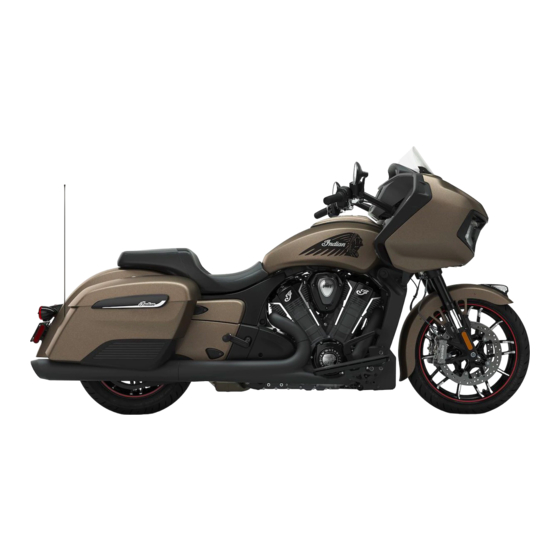
2020-2024 Indian Challenger / Pursuit
Service Manual
FOREWORD
The information printed within this publication includes the latest product information at time of print. The most
recent version of this Service Manual is available in electronic format at www.polarisdealers.com.
This Service Manual is designed primarily for use by certified Indian Motorcycle Master Service Dealer
®
technicians in a properly equipped shop and should be kept available for reference. All references to left and
right side of the vehicle are from the operator's perspective when seated in a normal riding position.
Some procedures outlined in this manual require a sound knowledge of mechanical theory, tool use, and shop
procedures in order to perform the work safely and correctly. Technicians should read the text and be familiar
with the service procedures before starting any repair. Certain procedures require the use of special tools. Use
only the proper tools as specified. If you have any doubt as to your ability to perform any of the procedures
outlined in this Service Manual, contact an authorized dealer for service.
We value your input and appreciate any assistance you can provide in helping make these publications more
useful. Please provide any feedback you may have regarding this manual. Authorized dealers can submit
feedback using 'Ask Polaris'. Click on 'Ask Polaris', and then click on 'Service Manual / Service Literature
Question'.
Publication Printed November 2023 (PN 9941349 R04)
© Copyright 2023 All information contained within this publication is based on the latest product information at the time of publication. Due to constant
improvements in the design and quality of production components, some minor discrepancies may result between the actual vehicle and the information
presented in this publication. Depictions and/or procedures in this publication are intended for reference use only. No liability can be accepted for omissions or
inaccuracies. Any reprinting or reuse of the depictions and/or procedures contained within, whether whole or in part, is expressly prohibited. Printed in U.S.A.
Advertisement
Table of Contents
Troubleshooting

Related Manuals for Indian Motorcycle Challenger 2020


Summary of Contents for Indian Motorcycle Challenger 2020
- Page 1 The information printed within this publication includes the latest product information at time of print. The most recent version of this Service Manual is available in electronic format at www.polarisdealers.com. This Service Manual is designed primarily for use by certified Indian Motorcycle Master Service Dealer ®...
-
Page 2: Safety Warnings
Torx®, is a registered Trademark of Textron. Garmin®, is a registered trademark of Garmin, Ltd. Some Indian Motorcycle factory publications can be downloaded from www. polarisindustries. com, purchased from www.purepolaris.com or by contacting the nearest Indian Motorcycle dealer. REVISION INDEX... -
Page 3: Feedback Form
DATE CHANGES Updated battery charging, ignition coil test, and camshaft timing 12/11/2023 procedures Added front and rear master cylinder diaphragm return to neutral images 2/22/2024 FEEDBACK FORM A feedback form has been created for the technician or consumer to provide Polaris with an overall satisfaction rating for this service manual, provide comments on your experience or upload pictures/video. - Page 5 2020-2024 Indian Challenger / Pursuit Service Manual Chapter Summary CHAPTER 1 : GENERAL / SPECIFICATIONS CHAPTER 2 : MAINTENANCE CHAPTER 3 : ENGINE / COOLING / EXHAUST CHAPTER 4 : FUEL DELIVERY / EFI CHAPTER 5 : CLUTCH / PRIMARY / SHIFT CHAPTER 6 : TRANSMISSION / CRANKSHAFT CHAPTER 7 :...
-
Page 7: Chapter 1 General / Specifications
GENERAL / SPECIFICATIONS CHAPTER 1 GENERAL / SPECIFICATIONS VEHICLE INFORMATION................1.2 . - Page 8 GENERAL / SPECIFICATIONS V V E E H H I I C C L L E E I I N N F F O O R R M M A A T T I I O O N N M M O O D D E E L L N N U U M M B B E E R R D D E E S S I I G G N N A A T T I I O O N N Example: N21LCACCA1 TYPE MODEL...
- Page 9 GENERAL / SPECIFICATIONS E E N N G G I I N N E E N N U U M M B B E E R R L L O O C C A A T T I I O O N N M M A A N N U U F F A A C C T T U U R R E E R R L L A A B B E E L L The engine number is stamped into the bottom of...
- Page 10 GENERAL / SPECIFICATIONS G G E E N N E E R R A A L L S S P P E E C C I I F F I I C C A A T T I I O O N N S S 2 2 0 0 2 2 0 0 M M O O D D E E L L S S P P E E C C I I F F I I C C A A T T I I O O N N S S NOTICE Challenger Premium Shown.
- Page 11 GENERAL / SPECIFICATIONS Rear: 41 psi (283 kPa) CHASSIS Front Suspension Type / Inverted Telescopic Fork / 5.12” (130 mm) Travel Front Suspension Diameter 43 mm Rear Suspension Type / Single shock with hydraulic adjuster / 4.5” (114 mm) Travel Front Brakes Dual / 320 mm Semi-floating Rotor / 4 Piston Caliper Rear Brakes...
- Page 12 GENERAL / SPECIFICATIONS Overall Gear Ratio 1st Gear 10.169:1 2nd Gear 6.933:1 3rd Gear 5.151:1 4th Gear 4.105:1 5th Gear 3.508:1 6th Gear 3.017:1 9941349 R04 - 2020-2024 Indian Challenger / Pursuit Service Manual © Copyright...
- Page 13 GENERAL / SPECIFICATIONS 2 2 0 0 2 2 1 1 M M O O D D E E L L S S P P E E C C I I F F I I C C A A T T I I O O N N S S NOTICE Challenger Dark Horse Shown.
- Page 14 GENERAL / SPECIFICATIONS CHASSIS Front Suspension Type / Inverted Telescopic Fork / 5.12” (130 mm) Travel Front Suspension Diameter 43 mm Rear Suspension Type / Single shock with hydraulic adjuster / 4.5” (114 mm) Travel Front Brakes Dual / 320 mm Semi-floating Rotor / 4 Piston Caliper Rear Brakes Single / 298 mm Floating Rotor / 2 Piston Caliper MODEL 2021...
- Page 15 GENERAL / SPECIFICATIONS 1st Gear 10.169:1 2nd Gear 6.933:1 3rd Gear 5.151:1 4th Gear 4.105:1 5th Gear 3.508:1 6th Gear 3.017:1 9941349 R04 - 2020-2024 Indian Challenger / Pursuit Service Manual © Copyright...
- Page 16 GENERAL / SPECIFICATIONS 2 2 0 0 2 2 2 2 M M O O D D E E L L S S P P E E C C I I F F I I C C A A T T I I O O N N S S NOTICE Pursuit Limited Shown.
- Page 17 GENERAL / SPECIFICATIONS Rear Wheel Size / 16” x 5” Cast Type Front Tire Type / 130/60B19 66H / Metzeler Cruisetec Size Rear Tire Type / 180/60R16 80H (I) / Metzeler Cruisetec Size Front: 36 psi (248 kPa) Tire Pressures Rear: 41 psi (283 kPa) CHASSIS Front Suspension...
- Page 18 GENERAL / SPECIFICATIONS 3rd Gear Ratio 1.385:1 4th Gear Ratio 1.103:1 5th Gear Ratio 0.943:1 6th Gear Ratio 0.811:1 1 Down / 5 Up Gear Shift Pattern Final Drive Type Belt Drive , 152 Tooth Final Drive Ratio 2.379:1 Overall Gear Ratio 1st Gear 10.169:1 2nd Gear...
- Page 19 GENERAL / SPECIFICATIONS 2 2 0 0 2 2 3 3 M M O O D D E E L L S S P P E E C C I I F F I I C C A A T T I I O O N N S S NOTICE Challenger Base Shown.
- Page 20 GENERAL / SPECIFICATIONS Rear Wheel Size / 16” x 5” Cast Type Front Tire Type / 130/60B19 66H / Metzeler Cruisetec Size Rear Tire Type / 180/60R16 80H (I) / Metzeler Cruisetec Size Front: 36 psi (248 kPa) Tire Pressures Rear: 41 psi (283 kPa) CHASSIS Front Suspension...
- Page 21 GENERAL / SPECIFICATIONS MODEL 2023 ALL MODELS ENGINE Engine Type Power Plus 108 Displacement 108 cid (1768 cc) Compression Ratio 11.0:1 Valve Train 4 Valves per cylinder, SOHC, Hydraulic lifters Bore and Stroke 108 mm x 96.5 mm Fuel System / Throttle Body Closed loop fuel injection / 52 mm dual bore Bore Exhaust System...
- Page 22 GENERAL / SPECIFICATIONS 2 2 0 0 2 2 4 4 M M O O D D E E L L S S P P E E C C I I F F I I C C A A T T I I O O N N S S NOTICE Challenger Dark Horse Shown.
- Page 23 GENERAL / SPECIFICATIONS Rear Wheel Size / 16” x 5” Cast Type Front Tire Type / 130/60B19 66H / Metzeler Cruisetec Size Rear Tire Type / 180/60R16 80H (I) / Metzeler Cruisetec Size Front: 36 psi (248 kPa) Tire Pressures Rear: 41 psi (283 kPa) CHASSIS Front Suspension...
- Page 24 GENERAL / SPECIFICATIONS MODEL 2024 ALL MODELS ENGINE Engine Type Power Plus 108 Displacement 108 cid (1768 cc) Compression Ratio 11.0:1 Valve Train 4 Valves per cylinder, SOHC, Hydraulic lifters Bore and Stroke 108 mm x 96.5 mm Fuel System / Throttle Body Closed loop fuel injection / 52 mm dual bore Bore Exhaust System...
- Page 25 GENERAL / SPECIFICATIONS V V E E H H I I C C L L E E L L O O A A D D I I N N G G G G R R O O S S S S V V E E H H I I C C L L E E W W E E I I G G H H T T R R A A T T I I N N G G ( ( G G V V W W R R ) ) WARNING Exceeding the gross vehicle weight rating of your motorcycle can reduce stability and handling and...
- Page 26 GENERAL / SPECIFICATIONS E E M M M M I I S S I I O O N N S S I I N N F F O O R R M M A A T T I I O O N N E E M M I I S S S S I I O O N N C C O O N N T T R R O O L L S S Y Y S S T T E E M M S S 6.
- Page 27 Special tools may be required while servicing this vehicle. Some of the tools listed or depicted are mandatory, while other tools may be substituted with a similar tool, if available. Indian Motorcycle recommends use of the Special Tools referenced in the chapters of this service manual when servicing any Indian Motorcycle product.
- Page 28 GENERAL / SPECIFICATIONS S S P P E E C C I I A A L L T T O O O O L L S S I I N N D D E E X X ABS Tool (Brake Lever Reserve) Battery Tester Bearing Removal Kit PV-50104...
- Page 29 GENERAL / SPECIFICATIONS Crankshaft Rotation Tool Damper Rod Holder Electrical Tester Kit PV-49453 PF-51239 PV-43526 Engine Stand Adapter Fork Spring Compressor Adapter Fork Oil Level Tool PF-51240 PV-49464 PV-59000-A Inverted Fork Seal Installer Fork Spring Compressor Fuel Pressure Adapter PV-47035 PV-49463 PV-48656 Spanner Socket (Stem)
- Page 30 GENERAL / SPECIFICATIONS Swing-Arm Bushing Tool TPMS Activation Tool TPMS Activation Tool PF-51237 PF-51288 PF-51288-A Relay Bypass Tool Output Shaft Seal Tool USB to Serial Adapter PU-49466 PF-51243 PU-50621 Rocker Arm Compression Tool Oil Pressure Gauge Valve Spring Compressor Tool PF-52939 PV-43531 PV-1253...
- Page 31 GENERAL / SPECIFICATIONS Straightedge, Feeler Gauge Seal Guide (43mm) MultiLink XP Commercially Available PV-47037 PU-52792 9941349 R04 - 2020-2024 Indian Challenger / Pursuit Service Manual 1.25 © Copyright...
- Page 32 GENERAL / SPECIFICATIONS D D I I G G I I T T A A L L W W R R E E N N C C H H D D I I G G I I T T A A L L W W R R E E N N C C H H I I I I U U S S E E R R M M A A N N U U A A L L D D I I G G I I T T A A L L W W R R E E N N C C H H D D I I A A G G N N O O S S T T I I C C C C O O N N N N E E C C T T O O R R Review the Digital Wrench II user manual for The diagnostic connector...
- Page 33 GENERAL / SPECIFICATIONS R R E E F F E E R R E E N N C C E E M M A A S S T T E E R R T T O O R R Q Q U U E E T T A A B B L L E E Cooling Fan Fastener 35 in-lbs (4 N·m) CHAPTER 2: MAINTENANCE...
- Page 34 GENERAL / SPECIFICATIONS 88 in-lbs (10 N·m) Intake Manifold Sidestand Switch 44 in-lbs (5 N·m) Fasteners (left-hand Fastener side) Speaker Assembly 35 in-lbs (4 N·m) Intake Manifold Fastener 80 in-lbs (9 N·m) Fasteners (right-hand side installed with Sprag Clutch Fastener 88 in-lbs (10 N·m) special tool 5264374) 88 in-lbs (10 N·m)
- Page 35 GENERAL / SPECIFICATIONS CHAPTER 4: FUEL DELIVERY / EFI CHAPTER 5: CLUTCH / PRIMARY / SHIFT ITEM TORQUE ITEM TORQUE Airbox Hatch Cover Clutch Cable Mount 88 in-lbs (10 N·m) 88 in-lbs (10 N·m) Fastener Fastener Airbox Filter Cover Cold Start Cover 88 in-lbs (10 N·m) 88 in-lbs (10 N·m) Fastener...
- Page 36 GENERAL / SPECIFICATIONS CHAPTER 7: FRAME / BODY Fog Light Bracket 35 in-lbs (4 N·m) Fastener ITEM TORQUE Footpeg Fastener 35 ft-lbs (47 N·m) ABS Mount Bracket 88 in-lbs (10 N·m) Fastener (Allen Head) 45 ft-lbs (61 N·m) Front Downcast Fastener ABS Mount Bracket Fuel Tank Mount Bracket 88 in-lbs (10 N·m)
- Page 37 GENERAL / SPECIFICATIONS Ride Command Display Visor Top Fastener 35 in-lbs (4 N·m) 35 in-lbs (4 N·m) Fastener 15 in-lbs (2 N·m) VCM2 Fastener Saddlebag Fastener 18 ft-lbs (24 N·m) 15 in-lbs (2 N·m) Wire Cover Fastener Saddlebag Lock Fastener 62 in-lbs (7 N·m) Wire Guide Fastener 15 in-lbs (2 N·m)
- Page 38 GENERAL / SPECIFICATIONS CHAPTER 8: STEERING / SUSPENSION Steering Lock Fastener 18 ft-lbs (24 N·m) ITEM TORQUE Swing-Arm Pivot Shaft 96 in-lbs (11 N·m) Axle Nut (Rear) 65 ft-lbs (84 N·m) Swing-Arm Pivot Jam Nut 75 ft-lbs (101 N·m) 96 in-lbs (11 N·m) Belt Guard Fastener Swing-Arm Pivot Nut 65 ft-lbs (88 N·m)
- Page 39 GENERAL / SPECIFICATIONS Master Cylinder Clamp Starter Solenoid 44 in-lbs (5 N·m) 96 in-lbs (11 N·m) Fastener (Front) Terminal Fastener 88 in-lbs (10 N·m) Starter Terminal Fastener Master Cylinder Cover 18 in-lbs (2 N·m) Fastener (Front) Tail Light Mount Bracket 88 in-lbs (10 N·m) Fastener Master Cylinder Cover...
- Page 40 GENERAL / SPECIFICATIONS S S A A E E T T A A P P D D R R I I L L L L S S I I Z Z E E S S M M E E T T R R I I C C T T A A P P D D R R I I L L L L S S I I Z Z E E S S THREAD SIZE / DRILL THREAD SIZE / DRILL DECIMAL...
- Page 41 GENERAL / SPECIFICATIONS D D E E C C I I M M A A L L E E Q Q U U I I V V A A L L E E N N T T S S 1/64 in = .0156 in 39/64 in = .6094 in 1/32 in = .0312 in [1 mm = .0394 in] 5/8 in = .625 in [16mm=.
- Page 42 GENERAL / SPECIFICATIONS F F A A H H R R E E N N H H E E I I T T T T O O C C E E L L S S I I U U S S C to F: 9 ( C + 40) ¸...
- Page 43 GENERAL / SPECIFICATIONS M M E E A A S S U U R R E E M M E E N N T T C C O O N N V V E E R R S S I I O O N N C C H H A A R R T T UNIT OF MULTIPLIED COVERTS TO...
- Page 44 GENERAL / SPECIFICATIONS NOTES 9941349 R04 - 2020-2024 Indian Challenger / Pursuit Service Manual 1.38 © Copyright...
-
Page 45: Maintenance Intervals
........2.3 INDIAN MOTORCYCLE SERVICE PRODUCTS AND LUBRICANTS . - Page 46 50/50 Premix Extended Life 2.5 qts (2.4L) Coolant Antifreeze 2020: 16.4 oz (485 cc) per leg Indian Motorcycle Fork Oil Fork Oil 2021-2022: 18.1 oz (535 cc) per leg Total Usable: 6.0 gal (22.7 L) / Reserve 91 Octane (Recommended) Fuel 1.0 gal (3.8 L)
- Page 47 MAINTENANCE I I N N D D I I A A N N M M O O T T O O R R C C Y Y C C L L E E S S E E R R V V I I C C E E P P R R O O D D U U C C T T S S A A N N D D L L U U B B R R I I C C A A N N T T S S MAINTENANCE PRODUCT PART NUMBERS PART...
- Page 48 IMPORTANT Indian Motorcycle recommends performing a Engine Oil & Filter change every 12 months regardless of milage. XU - Perform these procedures more often for vehicles subjected to severe use. D - Have an authorized Indian Motorcycle dealer perform these services.
-
Page 49: Cooling System / Radiator
MAINTENANCE COOLING SYSTEM / RADIATOR INSPECT Lubricate with proper lubricant as directed Sidestand Steering Bearings Inspect Suspension Linkage, Rear Inspect Swing Arm and Rear Axle Inspect Inspect tread depth, sidewall cracking, wear patterns Tires / Wheels 9941349 R04 - 2020-2024 Indian Challenger / Pursuit Service Manual ©... - Page 50 MAINTENANCE 2,500 MILE (4,000 KM) SERVICE ITEM REMARKS Inspect; clean Air Filter Cooling System / Radiator Inspect Crankcase Ventilation System Inspect; tighten, clean, adjust Visual inspection for cracks or deformation is required whenever the rear Damper, Cushion Drive wheel is removed. Replace if damage is found. Inspect;...
- Page 51 MAINTENANCE 5,000 MILE (8,000 KM) SERVICE ITEM REMARKS Inspect; clean Air Filter Cooling System / Radiator Inspect Crankcase Ventilation System Inspect; tighten, clean, adjust Visual inspection for cracks or deformation is required whenever the rear Damper, Cushion Drive wheel is removed. Replace if damage is found. Inspect;...
- Page 52 MAINTENANCE 10,000 MILE (16,000 KM) SERVICE ITEM REMARKS Replace Air Filter Cooling System / Radiator Inspect Crankcase Ventilation System Inspect; tighten, clean, adjust Visual inspection for cracks or deformation is required whenever the rear Damper, Cushion Drive wheel is removed. Replace if damage is found. Inspect;...
- Page 53 MAINTENANCE 15,000 MILE (24,000 KM) SERVICE ITEM REMARKS Inspect; clean Air Filter Cooling System / Radiator Inspect Crankcase Ventilation System Inspect; tighten, clean, adjust Visual inspection for cracks or deformation is required whenever the rear Damper, Cushion Drive wheel is removed. Replace if damage is found. Inspect;...
- Page 54 MAINTENANCE 20,000 MILE (32,000 KM) SERVICE ITEM REMARKS Replace Air Filter Cooling System / Radiator Inspect Crankcase Ventilation System Inspect; tighten, clean, adjust Visual inspection for cracks or deformation is required whenever the rear Damper, Cushion Drive wheel is removed. Replace if damage is found. Inspect;...
- Page 55 MAINTENANCE 25,000 MILE (40,000 KM) SERVICE ITEM REMARKS Inspect; clean Air Filter Cooling System / Radiator Inspect Crankcase Ventilation System Inspect; tighten, clean, adjust Visual inspection for cracks or deformation is required whenever the rear Damper, Cushion Drive wheel is removed. Replace if damage is found. Inspect;...
- Page 56 MAINTENANCE 30,000 MILE (48,000 KM) SERVICE ITEM REMARKS Replace Air Filter Cooling System / Radiator Inspect Crankcase Ventilation System Inspect; tighten, clean, adjust Visual inspection for cracks or deformation is required whenever the rear Damper, Cushion Drive wheel is removed. Replace if damage is found. Replace Drive Belt Engine Coolant...
- Page 57 MAINTENANCE 35,000 MILE (52,000 KM) SERVICE ITEM REMARKS Inspect; clean Air Filter Cooling System / Radiator Inspect Crankcase Ventilation System Inspect; tighten, clean, adjust Visual inspection for cracks or deformation is required whenever the rear Damper, Cushion Drive wheel is removed. Replace if damage is found. Inspect;...
- Page 58 MAINTENANCE 40,000 MILE (64,000 KM) SERVICE ITEM REMARKS Replace Air Filter Cooling System / Radiator Inspect Crankcase Ventilation System Inspect; tighten, clean, adjust Visual inspection for cracks or deformation is required whenever the rear Damper, Cushion Drive wheel is removed. Replace if damage is found. Inspect;...
- Page 59 MAINTENANCE 45,000 MILE (72,000 KM) SERVICE ITEM REMARKS Inspect; clean Air Filter Cooling System / Radiator Inspect Crankcase Ventilation System Inspect; tighten, clean, adjust Visual inspection for cracks or deformation is required whenever the rear Damper, Cushion Drive wheel is removed. Replace if damage is found. Inspect;...
- Page 60 MAINTENANCE 50,000 MILE (80,000 KM) SERVICE ITEM REMARKS Replace Air Filter Cooling System / Radiator Inspect Crankcase Ventilation System Inspect; tighten, clean, adjust Visual inspection for cracks or deformation is required whenever the rear Damper, Cushion Drive wheel is removed. Replace if damage is found. Inspect;...
-
Page 61: Break-In Procedure
When inspection reveals the need for follow all break-in procedures to ensure the long-term replacement parts, use genuine Indian Motorcycle performance and durability of the engine. parts available from your Indian Motorcycle dealer. IMPORTANT CAUTION Service and adjustments are critical. If you’re not... - Page 62 MAINTENANCE R R O O U U T T I I N N E E M M A A I I N N T T E E N N A A N N C C E E P P R R O O C C E E D D U U R R E E S S E E N N G G I I N N E E O O I I L L &...
- Page 63 Approximately 3/4 turn after seal has contacted the filter adapter. 11. Remove the dipstick. Add only 4 qts (3.8 L) of Indian Motorcycle 15–W60 oil. Do NOT overfill. 12. Reinstall the dipstick securely. 13. With the unit in an upright, centered position. Start the engine and idle for 30 seconds.
- Page 64 MAINTENANCE E E N N G G I I N N E E O O I I L L L L E E V V E E L L 6. Add the recommended oil as needed to bring the level between the ADD and FULL marks. Do not With the semi-dry sump lubrication system, the add oil if between the ADD and FULL marks.
- Page 65 MAINTENANCE M M I I N N I I M M U U M M T T R R E E A A D D D D E E P P T T H H ( ( A A L L L L M M O O D D E E L L S S ) ) 4.
- Page 66 MAINTENANCE 2. View fluid level through reservoir sight glass 6. Carefully add enough DOT 4 brake fluid to bring The fluid should be clear and at a level between level to the upper edge of the sight glass. UPPER and LOWER level marks. 7.
- Page 67 MAINTENANCE 4. Measure electrode gap with a wire gauge Adjust gap if necessary by carefully bending the grounding electrode until the specified gap is achieved. Spark Plug Type: NGK LZMAR8AI-10 Spark Plug Gap: 0.039 in (1.0 mm) 9941349 R04 - 2020-2024 Indian Challenger / Pursuit Service Manual 2.23 ©...
- Page 68 Indian Motorcycle recommends using the BatteryMINDer® 2012 AGM - 2 AMP battery charger (PN 2830438) to charge and maintain AGM batteries. The charger can be found on the Polaris and Indian Motorcycle PG&A websites and ordered in DEX – Item Availability.
- Page 69 MAINTENANCE A A G G M M B B A A T T T T E E R R Y Y C C H H A A R R G G I I N N G G R R E E C C O O M M M M E E N N D D A A T T I I O O N N S S The battery will self-discharge when disconnected from a vehicle, and will discharge at a faster rate when connected.
- Page 70 MAINTENANCE A A G G M M B B A A T T T T E E R R Y Y C C H H A A R R G G I I N N G G R R E E C C O O M M M M E E N N D D A A T T I I O O N N S S – – D D E E E E P P L L Y Y D D I I S S C C H H A A R R G G E E D D ( ( B B E E L L O O W W 3 3 V V O O L L T T S S ) ) NOTICE If the automatic charger's manual does not include instructions on how to charge deeply discharged batteries, then use the following procedure.
- Page 71 MAINTENANCE A A G G M M B B A A T T T T E E R R Y Y M M A A I I N N T T E E N N A A N N C C E E T T I I P P S S 1.
- Page 72 MAINTENANCE F F U U S S E E R R E E P P L L A A C C E E M M E E N N T T 3. If any fuse is blown, turn off main switch. Install new fuse of specified amperage.
- Page 73 MAINTENANCE H H E E A A D D L L I I G G H H T T A A I I M M A A D D J J U U S S T T M M E E N N T T 7.
-
Page 74: Maintenance Procedure
MAINTENANCE M M A A J J O O R R M M A A I I N N T T E E N N A A N N C C E E P P R R O O C C E E D D U U R R E E S S IMPORTANT Reference the Maintenance Intervals page 2.4 for details on how often to perform each procedure. - Page 75 MAINTENANCE MAINTENANCE PROCEDURE LOCATION Front Brake Lever Reach page 9.5 Front Brake Lever Reach Brake Pedal Inspection Brake Pedal Inspection page 9.5 Brake Pedal Lubrication page 9.5 Brake Pedal Lubrication Front Brake Pad Inspection Front Brake Pad Inspection page 9.6 Rear Brake Pad Inspection Rear Brake Pad Inspection page 9.6 Battery Removal...
- Page 76 MAINTENANCE NOTES 9941349 R04 - 2020-2024 Indian Challenger / Pursuit Service Manual 2.32 © Copyright...
- Page 77 ENGINE / COOLING / EXHAUST CHAPTER 3 ENGINE / COOLING / EXHAUST ENGINE / COOLING / EXHAUST MAINTENANCE ........... . 3.4 .
- Page 78 ENGINE / COOLING / EXHAUST ............. . .3.33 OIL PUMP REMOVAL / INSTALLATION .
- Page 79 ENGINE / COOLING / EXHAUST ................3.92 VALVE SEAT INSPECTION .
-
Page 80: Hot Components
ENGINE / COOLING / EXHAUST E E N N G G I I N N E E / / C C O O O O L L I I N N G G / / E E X X H H A A U U S S T T S S P P A A R R K K P P L L U U G G R R E E M M O O V V A A L L M M A A I I N N T T E E N N A A N N C C E E CAUTION... - Page 81 ENGINE / COOLING / EXHAUST S S P P A A R R K K P P L L U U G G I I N N S S T T A A L L L L A A T T I I O O N N 1.
- Page 82 ENGINE / COOLING / EXHAUST E E N N G G I I N N E E C C O O M M P P R R E E S S S S I I O O N N T T E E S S T T 12.
- Page 83 The crankcase ventilation system routes blow–by IMPORTANT gasses from the engine back into the intake tract. Indian Motorcycle strongly recommends using the cylinder leakdown method to determine how well the combustion chamber is sealing. 1. Pour 3-5 cc of clean engine oil into each cylinder through spark plug hole.
- Page 84 ENGINE / COOLING / EXHAUST A A I I R R C C L L E E A A N N E E R R S S E E R R V V I I C C E E A A I I R R F F I I L L T T E E R R R R E E P P L L A A C C E E M M E E N N T T I I N N L L E E T T A A D D A A P P T T E E R R R R E E M M O O V V A A L L / / I I N N S S T T A A L L L L A A T T I I O O N N R R E E M M O O V V A A L L NOTICE...
- Page 85 ENGINE / COOLING / EXHAUST I I N N L L E E T T T T U U B B E E R R E E P P L L A A C C E E M M E E N N T T 1.
-
Page 86: Specifications
ENGINE / COOLING / EXHAUST E E N N G G I I N N E E R R E E M M O O V V A A L L / / I I N N S S T T A A L L L L G G E E N N E E R R A A L L I I N N F F O O R R M M A A T T I I O O N N S S E E R R V V I I C C E E S S P P E E C C I I F F I I C C A A T T I I O O N N S S –... - Page 87 ENGINE / COOLING / EXHAUST A A S S S S E E M M B B L L Y Y V V I I E E W W S S E E N N G G I I N N E E B B R R A A C C K K E E T T S S / / F F A A S S T T E E N N E E R R S S LEFT SIDE BRACKETS / FASTENERS TORQUE ITEM...
- Page 88 ENGINE / COOLING / EXHAUST RIGHT SIDE BRACKETS / FASTENERS TORQUE ITEM DESCRIPTION 75 ft-lbs (102 N·m) Midcast M12 Fastener Engine / Frame Spacer — 45 ft-lbs (61 N·m) Front Downcast Fastener 9941349 R04 - 2020-2024 Indian Challenger / Pursuit Service Manual 3.12 ©...
- Page 89 ENGINE / COOLING / EXHAUST CYLINDER HEAD BRACKET / FASTENER TORQUE ITEM DESCRIPTION Cylinder Head Bracket Fastener 75 ft-lbs (102 N·m) 9941349 R04 - 2020-2024 Indian Challenger / Pursuit Service Manual 3.13 © Copyright...
- Page 90 ENGINE / COOLING / EXHAUST E E N N G G I I N N E E R R E E M M O O V V A A L L / / I I N N S S T T A A L L L L A A T T I I O O N N 9.
- Page 91 ENGINE / COOLING / EXHAUST R R E E M M O O V V I I N N G G E E N N G G I I N N E E F F R R O O M M F F R R A A M M E E 13.
- Page 92 ENGINE / COOLING / EXHAUST 6. Loosen the swingam axle nut 10. Loosen left hand Midcast fasteners . Repeat step for remaining side. 7. Remove shock rocker pivot shaft snap ring 11. During removal, ensure to retrieve frame / engine 8.
- Page 93 ENGINE / COOLING / EXHAUST E E N N G G I I N N E E I I N N S S T T A A L L L L A A T T I I O O N N 4.
- Page 94 ENGINE / COOLING / EXHAUST 7. Tighten engine mount fasteners. 11. Connect the stator electrical connectors and J- Case connector. TORQUE Engine Mount Fastener: 45 ft-lbs (61 N·m) TORQUE Cylinder Head Bracket Fastener: 75 ft-lbs (102 N·m) 8. Install breather fastener 12.
- Page 95 ENGINE / COOLING / EXHAUST 14. Tighten throttle body to inlet adapter clamps 16. Install brake line fastener TORQUE TORQUE P-clamp: Hose Clamp: 88 in-lbs (10 N·m) 26 in-lbs (3 N·m) 17. Install sidestand switch and secure with its 15. Connect electrical connector for: fasteners TORQUE Sidestand Switch Fastener...
- Page 96 ENGINE / COOLING / EXHAUST 21. Install driver’s floorboard. See Floorboard Removal / Installation page 7.29. 22. Install head pipe. See Headpipe Removal / Installation page 3.117. 23. Install radiator. See Radiator Removal / Installation page 3.38. 24. Install fuel tank. See Fuel Tank Installation (2020) page 4.42.
-
Page 97: Low Oil Pressure
ENGINE / COOLING / EXHAUST L L U U B B R R I I C C A A T T I I O O N N / / C C O O O O L L I I N N G G G G E E N N E E R R A A L L I I N N F F O O R R M M A A T T I I O O N N T T R R O O U U B B L L E E S S H H O O O O T T I I N N G G S S E E R R V V I I C C E E N N O O T T E E S S —... - Page 98 Engine Oil Capacity (At Change with Filter) Follow the oil change procedure outlined in the 5.0 qts (4.7 L) Not Applicable Maintenance chapter. Recommended Engine Oil if Indian Motorcycle Indian Motorcycle Semi-Synthetic 15W60 is not available, use motorcycle oil with Not Applicable 15W60 same specifications.
- Page 99 ENGINE / COOLING / EXHAUST A A S S S S E E M M B B L L Y Y V V I I E E W W S S F F I I L L T T E E R R A A D D A A P P T T E E R R TORQUE ITEM DESCRIPTION...
- Page 100 ENGINE / COOLING / EXHAUST O O I I L L F F L L O O W W D D I I A A G G R R A A M M 9941349 R04 - 2020-2024 Indian Challenger / Pursuit Service Manual 3.24 ©...
- Page 101 ENGINE / COOLING / EXHAUST L L U U B B R R I I C C A A T T I I O O N N S S Y Y S S T T E E M M TORQUE ITEM DESCRIPTION —...
- Page 102 ENGINE / COOLING / EXHAUST TORQUE ITEM DESCRIPTION Piston Cooling Jet — Piston Cooling Jet Fastener 62 in-lbs (7 N·m) Scavenge Oil Inlet Screen — Scavenge Oil Inlet Screen Fastener 88 in-lbs (10 N·m) Oil Pickup — Oil Pickup Fastener 88 in-lbs (10 N·m) Oil Scavenge Tube —...
- Page 103 ENGINE / COOLING / EXHAUST W W A A T T E E R R P P U U M M P P A A S S S S E E M M B B L L Y Y V V I I E E W W TORQUE ITEM DESCRIPTION...
- Page 104 ENGINE / COOLING / EXHAUST C C O O O O L L I I N N G G S S Y Y S S T T E E M M A A S S S S E E M M B B L L Y Y V V I I E E W W ITEM DESCRIPTION ITEM...
- Page 105 ENGINE / COOLING / EXHAUST T T H H E E R R M M O O S S T T A A T T A A S S S S E E M M B B L L Y Y V V I I E E W W TORQUE TORQUE ITEM...
- Page 106 ENGINE / COOLING / EXHAUST R R A A D D I I A A T T O O R R A A S S S S E E M M B B L L Y Y V V I I E E W W TORQUE ITEM DESCRIPTION...
-
Page 107: Oil Pump
ENGINE / COOLING / EXHAUST T T O O R R Q Q U U E E S S E E Q Q U U E E N N C C E E – – L L U U B B R R I I C C A A T T I I O O N N / / C C O O O O L L I I N N G G OIL PUMP 9941349 R04 - 2020-2024 Indian Challenger / Pursuit Service Manual 3.31... - Page 108 ENGINE / COOLING / EXHAUST O O I I L L P P R R E E S S S S U U R R E E I I N N S S P P E E C C T T I I O O N N O O I I L L P P R R E E S S S S U U R R E E CAUTION Use caution when working around hot engine oil.
- Page 109 ENGINE / COOLING / EXHAUST O O I I L L P P U U M M P P S S E E R R V V I I C C E E 5. Remove oil pump fasteners O O I I L L P P U U M M P P R R E E M M O O V V A A L L / / I I N N S S T T A A L L L L A A T T I I O O N N To watch a video of this procedure, scan the QR code or click HERE.
- Page 110 ENGINE / COOLING / EXHAUST 1. Install the gerotor onto the oil pump assembly so 4. Torque fasteners to specification. the pin fits in the recess in the gerotor. TORQUE Oil Pressure Feed Tube Fastener: 84 in-lbs (10 N·m) TORQUE Input Shaft Feed Tube Fastener: 88 in-lbs (10 N·m) TORQUE...
- Page 111 ENGINE / COOLING / EXHAUST T T R R A A N N S S M M I I S S S S I I O O N N F F E E E E D D R R A A I I L L 3.
-
Page 112: Installation
ENGINE / COOLING / EXHAUST INSTALLATION INCORRECT CAUTION • There will NO be no resistance felt due to the o-ring not seating in the pilot hole. • The transmission feed line goes through the left • The feed rail mounting tabs will NOT be case half and into the right casehalf into a tapered parallel with the case as shown. - Page 113 ENGINE / COOLING / EXHAUST C C O O O O L L I I N N G G S S Y Y S S T T E E M M S S E E R R V V I I C C E E 4.
- Page 114 ENGINE / COOLING / EXHAUST R R A A D D I I A A T T O O R R R R E E M M O O V V A A L L / / I I N N S S T T A A L L L L A A T T I I O O N N 8.
- Page 115 ENGINE / COOLING / EXHAUST 8. Remove downcast fasteners and battery box 12. Remove fan shroud by removing two push pins fastener 13. Disconnect the fan electrical connector. 9. Remove fairing louver by removing its fasteners 14. Disconnect the upper and lower radiator hoses by removing the spring clamps 10.
- Page 116 ENGINE / COOLING / EXHAUST C C O O O O L L A A N N T T R R E E C C O O V V E E R R Y Y B B O O T T T T L L E E R R E E M M O O V V A A L L / / INSTALLATION I I N N S S T T A A L L L L A A T T I I O O N N 1.
- Page 117 ENGINE / COOLING / EXHAUST W W A A T T E E R R P P U U M M P P R R E E M M O O V V A A L L / / I I N N S S T T A A L L L L A A T T I I O O N N 7.
- Page 118 ENGINE / COOLING / EXHAUST 6. Remove the water pump and water pump gasket 4. Install the water pump chain tensioner by rotating it upward into position. 5. Secure tensioner with its fastener. INSTALLATION TORQUE 1. Inspect the water pump gasket and replace if necessary.
- Page 119 ENGINE / COOLING / EXHAUST T T H H E E R R M M O O S S T T A A T T R R E E M M O O V V A A L L / / I I N N S S T T A A L L L L A A T T I I O O N N 6.
- Page 120 ENGINE / COOLING / EXHAUST 2. Connect cylinder coolant hose clamps 5. Install fasteners securing ignition coil bracket. Torque fasteners to specification. 3. Connect thermostat hose clamp and coolant return line clamp TORQUE Ignition Coil Bracket: 88 in-lbs (10 N·m) 6.
- Page 121 ENGINE / COOLING / EXHAUST 2. Remove coolant bypass tube 3. Inspect O-rings for damage and replace if necessary. ASSEMBLY 1. ASSEMBLY IS PERFORMED BY REVERSING THE DISASSEMBLY PROCEDURE. IMPORTANT Replace any damaged o-rings prior to assembly. TORQUE Thermostat Cover Fastener: 88 in-lbs (10 N·m) 9941349 R04 - 2020-2024 Indian Challenger / Pursuit Service Manual 3.45...
-
Page 122: Tool Description
ENGINE / COOLING / EXHAUST C C Y Y L L I I N N D D E E R R H H E E A A D D / / V V A A L L V V E E S S G G E E N N E E R R A A L L I I N N F F O O R R M M A A T T I I O O N N S S P P E E C C I I A A L L T T O O O O L L S S –... - Page 123 ENGINE / COOLING / EXHAUST S S E E R R V V I I C C E E S S P P E E C C I I F F I I C C A A T T I I O O N N S S – – C C Y Y L L I I N N D D E E R R H H E E A A D D CAMSHAFT DATA DESCRIPTION SPECIFICATION...
- Page 124 ENGINE / COOLING / EXHAUST CYLINDER HEAD & VALVE TRAIN DATA ITEM STANDARD SERVICE LIMIT Lobe Height 1.7991" (45.699 mm) 1.7952” (45.599 mm) INTAKE 1.78165" (45.254 mm) 1.7778” (45.154 mm) EXHAUST 2.244 +/- .00039" Cam Shaft Journal O.D. (Large) 2.2433” (56.98 mm) (57.00 +/- 0.01 mm) .6244 - .6250"...
- Page 125 ENGINE / COOLING / EXHAUST A A S S S S E E M M B B L L Y Y V V I I E E W W S S C C A A M M C C H H A A I I N N A A S S S S E E M M B B L L Y Y V V I I E E W W ITEM DESCRIPTION TORQUE...
- Page 126 ENGINE / COOLING / EXHAUST C C A A M M S S H H A A F F T T S S A A S S S S E E M M B B L L Y Y V V I I E E W W TORQUE ITEM DESCRIPTION...
- Page 127 ENGINE / COOLING / EXHAUST C C Y Y L L I I N N D D E E R R H H E E A A D D A A S S S S E E M M B B L L Y Y V V I I E E W W ITEM DESCRIPTION TORQUE...
- Page 128 ENGINE / COOLING / EXHAUST C C A A M M S S H H A A F F T T T T I I M M I I N N G G REAR CYLINDER When crankshaft is locked for REAR cylinder at TDC rear camshaft sprocket alignment should be in the position shown.
- Page 129 ENGINE / COOLING / EXHAUST FRONT CYLINDER When crankshaft is locked for the FRONT cylinder the front camshaft sprocket alignment should be in the position shown. CAUTION Failure to properly time the camshafts can lead to engine damage. For setting camshaft timing, refer to cam chain installation. See Cam Chain Removal / Installation page 3.57. 9941349 R04 - 2020-2024 Indian Challenger / Pursuit Service Manual 3.53 ©...
-
Page 130: Valve Cover
ENGINE / COOLING / EXHAUST T T O O R R Q Q U U E E S S E E Q Q U U E E N N C C E E – – C C Y Y L L I I N N D D E E R R H H E E A A D D / / V V A A L L V V E E S S VALVE COVER CYLINDER HEAD 9941349 R04 - 2020-2024 Indian Challenger / Pursuit Service Manual... - Page 131 ENGINE / COOLING / EXHAUST C C A A M M C C H H A A I I N N S S E E R R V V I I C C E E HOLDING THE CRANKSHAFT The crankshaft / rotating assembly can be held in L L O O C C K K I I N N G G T T H H E E C C R R A A N N K K S S H H A A F F T T F F O O R R S S E E R R V V I I C C E E place by an alternative method, however this method LOCKING THE CRANKSHAFT...
- Page 132 ENGINE / COOLING / EXHAUST F F L L Y Y W W H H E E E E L L R R E E M M O O V V A A L L / / I I N N S S T T A A L L L L A A T T I I O O N N 6.
- Page 133 ENGINE / COOLING / EXHAUST C C A A M M C C H H A A I I N N T T E E N N S S I I O O N N E E R R R R E E M M O O V V A A L L C C A A M M C C H H A A I I N N R R E E M M O O V V A A L L / / I I N N S S T T A A L L L L A A T T I I O O N N REMOVAL CAUTION...
- Page 134 ENGINE / COOLING / EXHAUST 8. Remove cam chain guides. 2. Install the rear cam chain through its slot in the cylinder head. 9. Remove cam chains off of crankshaft and remove. 3. Connect the chain to the inside sprocket on the crankshaft.
- Page 135 ENGINE / COOLING / EXHAUST 5. Align the camshaft sprocket as shown. 7. Install the rear cam chain tensioner NOTICE You can reference the Camshaft Timing diagram Camshaft Timing page 3.52 CAUTION Failure to properly time the camshafts can lead to engine damage.
- Page 136 ENGINE / COOLING / EXHAUST 10. Install the front cam chain through its slot in the 13. Align the camshaft sprocket as shown. cylinder head. NOTICE You can reference the Camshaft Timing diagram Camshaft Timing page 3.52 CAUTION Failure to properly time the camshafts can lead to engine damage.
- Page 137 ENGINE / COOLING / EXHAUST C C A A M M C C H H A A I I N N T T E E N N S S I I O O N N E E R R I I N N S S P P E E C C T T I I O O N N 16.
- Page 138 ENGINE / COOLING / EXHAUST C C A A M M S S H H A A F F T T S S P P R R O O C C K K E E T T R R E E M M O O V V A A L L / / 9.
- Page 139 ENGINE / COOLING / EXHAUST C C A A M M C C H H A A I I N N G G U U I I D D E E I I N N S S T T A A L L L L A A T T I I O O N N 7.
- Page 140 ENGINE / COOLING / EXHAUST C C A A M M S S H H A A F F T T S S E E R R V V I I C C E E • Clean the area around the scavenge drain plug .
-
Page 141: Seat Removal
ENGINE / COOLING / EXHAUST SEAT REMOVAL 4. Remove upper side cover 1. Remove tipover cover by removing its fastener 5. Remove seat fastener 2. Remove upper side cover 6. If equipped, disconnect seat electrical connector. 7. Remove the seat backward and up to remove. 3. -
Page 142: Disconnect The Battery
ENGINE / COOLING / EXHAUST DEPRESSURIZE THE FUEL SYSTEM DISCONNECT THE BATTERY 1. Remove chin fairing by removing its fasteners WARNING Allow engine and exhaust to cool completely before disconnecting fuel line or removing tank. Wear eye protection. 1. Locate the fuel pump relay. 2. - Page 143 ENGINE / COOLING / EXHAUST REMOVE OUTER FAIRING 5. Using Body Panel Tool kit PV-49955, remove headlight bezel by prying down at the top 1. Carefully pry off speaker bezels with Body Panel center to release the snap and then pull forward to Tool Kit PV-49955.
- Page 144 ENGINE / COOLING / EXHAUST REMOVE FRONT FENDER REMOVE FUEL TANK 1. Remove fasteners from each side of the 1. Remove left side v-cover by removing its fasteners motorcycle securing the fender. 2. Follow the fender light harness up into the fairing, 2.
- Page 145 ENGINE / COOLING / EXHAUST 3. Disconnect the fuel feed line from the fuel rail. 6. 2021 models only: Disconnect fuel tank electrical connectors CAUTION Do not use anything other than fingers to remove the quick connection. The use of tools can damage the connection.
- Page 146 ENGINE / COOLING / EXHAUST REMOVE RIGHT FLOORBOARD REMOVE LEFT FLOORBOARD 1. Remove rear master cylinder cotter pin 1. Remove fastener securing shift lever. pivot pin 2. Remove the fasteners securing the floorboard 2. Remove the fasteners securing the floorboard bracket.
- Page 147 ENGINE / COOLING / EXHAUST REMOVE SIDE STAND AND SWITCH REMOVE EXHAUST 1. Carefully remove the sidestand spring. 1. From underneath the right heatshield, loosen the exhaust clamp . Note orientation of clamp for 2. Remove the two fasteners securing the sidestand reassembly.
- Page 148 ENGINE / COOLING / EXHAUST 4. Move the resonator rearward and remove. 7. Carefully remove headpipe. IMPORTANT Be sure to disconnect the remaining oxygen sensor electrical connector during removal. 8. Remove and inspect the headpipe gasket damage and replace if necessary. 5.
- Page 149 ENGINE / COOLING / EXHAUST REMOVE STAGE CAMSHAFT d. Remove downcast fasteners 1. Loosen radiator and remove both down casts. a. Remove lower fairing bracket fasteners Repeat step for opposite side. e. Remove fairing louver by removing its fasteners b. On the inside of the fairing bracket, remove the speaker assembly fastener , and the dash closeout fastener...
- Page 150 ENGINE / COOLING / EXHAUST h. Remove fan shroud by removing two push pins 4. Loosen axle nut and belt tensioner. a. Make note of adjuster locations. b. Loosen axle nut then tighten to 15 ft-lbs (20 Nm). 2. Remove radiator filler neck from chassis by 3&...
- Page 151 ENGINE / COOLING / EXHAUST 5. Remove drive belt cover and lower belt guard, then 6. Disconnect gear position switch electrical remove the belt from the sprocket. connection a. 2020 Models: Remove the belt shield by removing its fasteners 7. Slide Belt off of drive sprocket. 8.
- Page 152 ENGINE / COOLING / EXHAUST 10. Loosen throttle body clamps b. Slide the ECM off of its pin. c. Lift the ECM up and disconnect its electrical 11. Near the battery box, disconnect the oil pressure connections. switch 13. At the rear of the mainframe, move brake lines 12.
- Page 153 ENGINE / COOLING / EXHAUST 14. Remove fasteners securing mainframe to d. During removal, ensure to retrieve frame / 5& breather. engine spacers 15. Remove engine mounts. 16. Lower the engine using the scissor jack and balance the engine on the jack. DO NOT a.
- Page 154 ENGINE / COOLING / EXHAUST c. Remove valve cover gasket c. Remove Flywheel by removing the flywheel bolt and washer NOTICE d. Install flywheel bolt back into crankshaft. Inspect gasket for damage. Replace as needed. e. Lock the crankshaft by inserting crankshaft locking pin PF-51235-A or a 5/16”...
- Page 155 ENGINE / COOLING / EXHAUST 19. Remove tensioners and sealing washers b. Install the special tool PF-52939 onto the cylinder head as shown. NOTICE Inspect sealing washer for damage. Replace as needed. c. Tighten the fasteners to compress the rocker arm assemblies.
- Page 156 ENGINE / COOLING / EXHAUST C C A A M M S S H H A A F F T T I I N N S S P P E E C C T T I I O O N N C C A A M M S S H H A A F F T T I I N N S S T T A A L L L L A A T T I I O O N N For the following camshaft inspection procedure, 1.
- Page 157 ENGINE / COOLING / EXHAUST 6. Reverse removal procedure for installation. TORQUE Transmission Shield Fastener (2021): TORQUE 88 in-lbs (10 N·m) Camshaft Sprocket Fastener 159 in-lbs (18 N·m) TORQUE Rear Axle Nut: TORQUE 65 ft-lbs (84 N·m) Cam Chain Tensioner: 15 ft-lbs (20 N·m) TORQUE Radiator Fill Nut Neck Fastener:...
- Page 158 ENGINE / COOLING / EXHAUST TORQUE TORQUE Headpipe Nuts: Fuel Tank Fastener: 1. Torque front header lower nut to 7 ft-lbs (9 N·m) 18 ft-lbs (24 N·m) 2.Torque front header upper nut to 7 ft-lbs (9 N·m) 3.Torque rear header bottom nut to 7 ft-lbs (9 N·m) TORQUE 4.Torque rear header top nut to 7 ft-lbs (9 N·m)5.
- Page 159 Approximately 3/4 turn after seal has contacted the filter adapter. 7. Remove the dipstick. Add only 4 qts (3.8 L) of Indian Motorcycle 15–W60 oil. Do NOT overfill. 8. Reinstall the dipstick securely. 9. With the unit in an upright, centered position. Start 12.
- Page 160 ENGINE / COOLING / EXHAUST 10. Stop the engine and add an additional 1 qts (0.95 L) 16. The approximate volume between the FULL of oil. marks on the dipstick is 32 oz. (.94 L). CAUTION Do NOT overfill. Overfilling can result in loss of engine performance and an oil saturated air filter.
- Page 161 ENGINE / COOLING / EXHAUST V V A A L L V V E E C C O O V V E E R R R R E E M M O O V V A A L L REMOVAL 1.
- Page 162 ENGINE / COOLING / EXHAUST V V A A L L V V E E C C O O V V E E R R I I N N S S T T A A L L L L A A T T I I O O N N C C Y Y L L I I N N D D E E R R H H E E A A D D R R E E M M O O V V A A L L 1.
- Page 163 ENGINE / COOLING / EXHAUST R R O O C C K K E E R R A A R R M M A A S S S S E E M M B B L L Y Y R R E E M M O O V V A A L L / / 4.
- Page 164 ENGINE / COOLING / EXHAUST R R O O C C K K E E R R A A R R M M A A S S S S E E M M B B L L Y Y I I N N S S P P E E C C T T I I O O N N C C Y Y L L I I N N D D E E R R H H E E A A D D D D I I S S A A S S S S E E M M B B L L Y Y NOTICE 1.
- Page 165 ENGINE / COOLING / EXHAUST V V A A L L V V E E I I N N S S P P E E C C T T I I O O N N 6. Clean gasket surfaces. NOTICE Valve service specifications can be found at the C C Y Y L L I I N N D D E E R R H H E E A A D D I I N N S S P P E E C C T T I I O O N N beginning of this chapter.
- Page 166 ENGINE / COOLING / EXHAUST b. Position dial indicator as shown. Measure deflection in two directions perpendicular to each other (X & Y axis). c. If valve deflection exceeds service limit measure valve stem diameter. 7. Replace valve and repeat step 6 if valve stem O.D. measures outside standard range.
- Page 167 ENGINE / COOLING / EXHAUST V V A A L L V V E E I I N N S S P P E E C C T T I I O O N N CONDITION ILLUSTRATION POSSIBLE CAUSE CORRECTIVE ACTION Uneven seat width Bent valve stem, worn Replace valve and reface...
- Page 168 ENGINE / COOLING / EXHAUST V V A A L L V V E E G G U U I I D D E E R R E E M M O O V V A A L L / / I I N N S S T T A A L L L L A A T T I I O O N N V V A A L L V V E E S S E E A A T T I I N N S S P P E E C C T T I I O O N N NOTICE CAUTION...
- Page 169 2. Thoroughly clean cylinder and cylinder head 3. Apply Indian Motorcycle engine oil to valve guide mating surfaces. seal and install seal on valve, rotating the seal as NOTICE you install it.
- Page 170 ENGINE / COOLING / EXHAUST 5. Install washers , nuts , and bolts . Tighten finger tight. IMPORTANT Add engine oil to the studs and bottom side of the cylinder head nuts. 6. Fully torque cylinder head following the procedure below to ensure accurate final torque: TORQUE Cylinder Head Nuts:...
- Page 171 ENGINE / COOLING / EXHAUST T T R R O O U U B B L L E E S S H H O O O O T T I I N N G G , , C C Y Y L L I I N N D D E E R R H H E E A A D D A A N N D D V V A A L L V V E E T T R R A A I I N N NOTICE Cylinder head, valve train and piston/cylinder problems are usually detected by an engine compression test.
- Page 172 ENGINE / COOLING / EXHAUST PROBLEM POSSIBLE CAUSE PART(S) AFFECTED REPAIR RECOMMENDED Worn Camshaft or Rocker Replace Rocker Arm Bearing Replace Damage Cam Bearings Worn or Replace Damaged Worn Pistons and / or Replace Cylinders Worn Wrist Pin, Wrist Pin Replace Piston / Cylinder Area Bore and / or Connecting...
- Page 173 ENGINE / COOLING / EXHAUST C C Y Y L L I I N N D D E E R R / / P P I I S S T T O O N N G G E E N N E E R R A A L L I I N N F F O O R R M M A A T T I I O O N N S S P P E E C C I I A A L L T T O O O O L L S S –...
-
Page 174: Service Limit
ENGINE / COOLING / EXHAUST S S E E R R V V I I C C E E S S P P E E C C I I F F I I C C A A T T I I O O N N S S – – C C Y Y L L I I N N D D E E R R / / P P I I S S T T O O N N ITEM STANDARD... - Page 175 ENGINE / COOLING / EXHAUST A A S S S S E E M M B B L L Y Y V V I I E E W W S S C C Y Y L L I I N N D D E E R R / / P P I I S S T T O O N N A A S S S S E E M M B B L L Y Y V V I I E E W W TORQUE ITEM DESCRIPTION...
-
Page 176: Piston Rings
ENGINE / COOLING / EXHAUST C C Y Y L L I I N N D D E E R R / / P P I I S S T T O O N N S S E E R R V V I I C C E E P P I I S S T T O O N N R R I I N N G G P P R R O O F F I I L L E E A A N N D D O O R R I I E E N N T T A A T T I I O O N N PISTON RINGS ITEM... - Page 177 ENGINE / COOLING / EXHAUST PISTON RING END GAP ORIENTATION ITEM DESCRIPTION Top Compression Ring Lower Compression Ring Top Oil Ring Oil Ring Expander Lower Oil Ring 9941349 R04 - 2020-2024 Indian Challenger / Pursuit Service Manual 3.101 © Copyright...
- Page 178 ENGINE / COOLING / EXHAUST C C Y Y L L I I N N D D E E R R R R E E M M O O V V A A L L C C Y Y L L I I N N D D E E R R B B O O R R E E M M E E A A S S U U R R E E M M E E N N T T 1.
- Page 179 ENGINE / COOLING / EXHAUST P P I I S S T T O O N N T T O O C C Y Y L L I I N N D D E E R R C C L L E E A A R R A A N N C C E E W W O O R R K K S S H H E E E E T T Front Cylinder Recorded Measurement Specification...
- Page 180 ENGINE / COOLING / EXHAUST C C Y Y L L I I N N D D E E R R W W A A R R P P A A G G E E M M E E A A S S U U R R E E M M E E N N T T P P I I S S T T O O N N &...
- Page 181 ENGINE / COOLING / EXHAUST P P I I S S T T O O N N & & P P I I S S T T O O N N R R I I N N G G I I N N S S P P E E C C T T I I O O N N P P I I S S T T O O N N P P I I N N / / P P I I N N B B O O R R E E I I N N S S P P E E C C T T I I O O N N 1.
- Page 182 ENGINE / COOLING / EXHAUST P P I I S S T T O O N N I I N N S S T T A A L L L L A A T T I I O O N N 5.
- Page 183 ENGINE / COOLING / EXHAUST C C Y Y L L I I N N D D E E R R S S T T U U D D R R E E P P L L A A C C E E M M E E N N T T 5.
- Page 184 ENGINE / COOLING / EXHAUST T T R R O O U U B B L L E E S S H H O O O O T T I I N N G G , , C C Y Y L L I I N N D D E E R R / / P P I I S S T T O O N N PROBLEM POSSIBLE CAUSE PART(S) AFFECTED...
- Page 185 ENGINE / COOLING / EXHAUST PROBLEM POSSIBLE CAUSE PART(S) AFFECTED REPAIR RECOMMENDED Worn Pistons and / or Replace Cylinders Replace Worn Wrist Pin, Wrist Pin Piston / Cylinder Area Bore and / or Connecting Worn Piston Rings or Replace Piston Ring Lands General Exhaust Leak Reseal Exhaust...
- Page 186 ENGINE / COOLING / EXHAUST C C Y Y L L I I N N D D E E R R L L E E A A K K A A G G E E T T E E S S T T •...
- Page 187 ENGINE / COOLING / EXHAUST E E X X H H A A U U S S T T E E X X H H A A U U S S T T S S Y Y S S T T E E M M A A S S S S E E M M B B L L Y Y V V I I E E W W 2 2 0 0 2 2 0 0 TORQUE TORQUE...
- Page 188 ENGINE / COOLING / EXHAUST 2 2 0 0 2 2 1 1 – – 2 2 0 0 2 2 2 2 TORQUE TORQUE ITEM DESCRIPTION ITEM DESCRIPTION Heat shield Clamp Headpipe 31 in-lbs (3 N·m) — (Rear) Headpipe Heat —...
- Page 189 ENGINE / COOLING / EXHAUST 2 2 0 0 2 2 3 3 + + ITEM DESCRIPTION TORQUE ITEM DESCRIPTION TORQUE Heat shield Clamp Headpipe 31 in-lbs (3 N·m) — (Rear) Headpipe Heat — Muffler — Shield (Front) Headpipe Heat 18 ft-lbs (24 N·m) —...
- Page 190 ENGINE / COOLING / EXHAUST E E X X H H A A U U S S T T S S E E R R V V I I C C E E 4. Remove muffler fasteners M M U U F F F F L L E E R R R R E E M M O O V V A A L L / / I I N N S S T T A A L L L L A A T T I I O O N N NOTICE The procedure shows only one muffler being removed for simplicity.
-
Page 191: Installation
ENGINE / COOLING / EXHAUST R R E E S S O O N N A A T T O O R R R R E E M M O O V V A A L L / / I I N N S S T T A A L L L L A A T T I I O O N N 4. - Page 192 ENGINE / COOLING / EXHAUST R R E E S S O O N N A A T T O O R R R R E E M M O O V V A A L L / / I I N N S S T T A A L L L L A A T T I I O O N N ( ( 2 2 0 0 2 2 3 3 4.
- Page 193 ENGINE / COOLING / EXHAUST H H E E A A D D P P I I P P E E R R E E M M O O V V A A L L / / I I N N S S T T A A L L L L A A T T I I O O N N 7.
- Page 194 ENGINE / COOLING / EXHAUST INSTALLATION 4. Remove headpipe nuts 1. INSTALLATION IS PERFORMED BY REVERSING THE REMOVAL PROCEDURE. TORQUE Headpipe Nuts: 1. Torque front header lower nut to 7 ft-lbs (9 N·m) 2.Torque front header upper nut to 7 ft-lbs (9 N·m) 3.Torque rear header bottom nut to 7 ft-lbs (9 N·m) 4.Torque rear header top nut to 7 ft-lbs (9 N·m)5.
- Page 195 FUEL DELIVERY / EFI CHAPTER 4 FUEL DELIVERY / EFI GENERAL INFORMATION ................4.3 .
- Page 196 FUEL DELIVERY / EFI ................. .4.52 ECM CONNECTOR MAP .
- Page 197 FUEL DELIVERY / EFI G G E E N N E E R R A A L L I I N N F F O O R R M M A A T T I I O O N N S S E E R R V V I I C C E E N N O O T T E E S S WARNING Many hazards are present when working on or around...
-
Page 198: Tool Description
FUEL DELIVERY / EFI S S P P E E C C I I A A L L T T O O O O L L S S – – F F U U E E L L D D E E L L I I V V E E R R Y Y / / E E F F I I TOOL DESCRIPTION PART NUMBER Electrical Tester Kit... - Page 199 FUEL DELIVERY / EFI F F U U E E L L D D E E L L I I V V E E R R Y Y / / E E F F I I M M A A I I N N T T E E N N A A N N C C E E F F U U E E L L T T A A N N K K V V E E N N T T I I N N S S P P E E C C T T I I O O N N 4 4 9 9 S S T T A A T T E E 1.
- Page 200 FUEL DELIVERY / EFI 5 5 0 0 S S T T A A T T E E / / I I N N T T L L 1. Inspect the Fuel vent to canister line in accordance with periodic maintenance schedule and any time fuel tank has been removed and installed.
- Page 201 FUEL DELIVERY / EFI E E V V A A P P O O R R A A T T I I V V E E E E M M I I S S S S I I O O N N C C O O N N T T R R O O L L S S Y Y S S T T E E M M – – 5 5 0 0 S S T T A A T T E E / / I I N N T T L L NOTICE The fuel tank vent line is routed to a carbon canister where the fuel vapor is stored until specific operating parameters are met and the ECM opens the purge valve.
- Page 202 Indian Motorcycle replacement parts. WARNING The fuel lines exiting fuel pump are subjected to high pressure. Replace with genuine Indian Motorcycle replacement parts to reduce the possibility of fuel line failure. Be sure fuel lines are routed properly and do not come in contact with sharp or hot objects, or anything that may cause wear or damage.
- Page 203 FUEL DELIVERY / EFI S S E E R R V V I I C C E E P P R R E E C C A A U U T T I I O O N N S S E E F F I I S S Y Y S S T T E E M M P P R R E E C C A A U U T T I I O O N N S S The ECM, VCM and sensors are sensitive pieces of electronic equipment.
- Page 204 FUEL DELIVERY / EFI Always use the proper adapter from the Connector Test Adapter Kit when probing the terminals. Most of the connectors are sealed and cannot be back probed. Be extremely careful not damage the connectors by forcing meter probes into the connectors. Use proper test adapters on connector pins Connector test adapter kit PV-43526 Poor connections are the most common cause of...
- Page 205 ITEM DESCRIPTION Fuel Cap: It is important to note that Indian Motorcycle does not use an enhanced EVAP control system. This means the system does not detect a gross leak, or restrictions in the EVAP system such as a missing or loose fuel cap. No check engine light will illuminate if the fuel cap is loose or missing.
- Page 206 FUEL DELIVERY / EFI E E V V A A P P C C O O N N D D I I T T I I O O N N S S A A N N D D S S Y Y M M P P T T O O M M S S C C A A R R B B O O N N C C A A N N I I S S T T E E R R R R E E M M O O V V A A L L / / I I N N S S T T A A L L L L A A T T I I O O N N The following conditions and symptoms should be...
- Page 207 FUEL DELIVERY / EFI P P U U R R G G E E V V A A L L V V E E T T E E S S T T I I N N G G / / R R E E P P L L A A C C E E M M E E N N T T 4.
- Page 208 FUEL DELIVERY / EFI A A S S S S E E M M B B L L Y Y V V I I E E W W S S F F U U E E L L L L I I N N E E R R O O U U T T I I N N G G – – 4 4 9 9 S S T T A A T T E E F F U U E E L L L L I I N N E E R R O O U U T T I I N N G G F F U U E E L L V V E E N N T T L L I I N N E E R R O O U U T T I I N N G G 9941349 R04 - 2020-2024 Indian Challenger / Pursuit Service Manual...
- Page 209 FUEL DELIVERY / EFI F F U U E E L L L L I I N N E E R R O O U U T T I I N N G G – – 5 5 0 0 S S T T A A T T E E F F U U E E L L L L I I N N E E R R O O U U T T I I N N G G F F U U E E L L V V E E N N T T L L I I N N E E R R O O U U T T I I N N G G 9941349 R04 - 2020-2024 Indian Challenger / Pursuit Service Manual...
- Page 210 FUEL DELIVERY / EFI F F U U E E L L P P U U R R G G E E L L I I N N E E R R O O U U T T I I N N G G 9941349 R04 - 2020-2024 Indian Challenger / Pursuit Service Manual 4.16 ©...
- Page 211 FUEL DELIVERY / EFI F F U U E E L L S S Y Y S S T T E E M M A A S S S S E E M M B B L L Y Y V V I I E E W W 4 4 9 9 / / 5 5 0 0 S S T T A A T T E E TORQUE ITEM...
- Page 212 FUEL DELIVERY / EFI 4 4 9 9 S S T T A A T T E E ITEM DESCRIPTION Fuel Line Fuel Vent Line 5 5 0 0 S S T T A A T T E E ITEM DESCRIPTION Fuel Line Fuel Vent to Canister...
- Page 213 FUEL DELIVERY / EFI A A I I R R B B O O X X A A S S S S E E M M B B L L Y Y V V I I E E W W TORQUE ITEM DESCRIPTION...
- Page 214 FUEL DELIVERY / EFI S S E E N N S S O O R R S S - - P P O O W W E E R R T T R R A A I I N N M M A A N N A A G G E E M M E E N N T T ITEM DESCRIPTION ITEM...
- Page 215 FUEL DELIVERY / EFI F F U U E E L L D D E E L L I I V V E E R R Y Y S S E E R R V V I I C C E E I I N N T T A A K K E E M M A A N N I I F F O O L L D D , , R R E E M M O O V V A A L L / / 4.
- Page 216 FUEL DELIVERY / EFI F F U U E E L L S S Y Y S S T T E E M M D D E E P P R R E E S S S S U U R R I I Z Z A A T T I I O O N N CAUTION Fuel lines remain under pressure at all times.
- Page 217 FUEL DELIVERY / EFI F F U U E E L L T T A A N N K K R R E E M M O O V V A A L L ( ( 2 2 0 0 2 2 0 0 ) ) 4.
- Page 218 FUEL DELIVERY / EFI 5 5 0 0 S S T T A A T T E E 5. Disconnect the fuel line from the fuel rail by squeezing both release buttons and gently sliding WARNING off the fuel rail. Allow engine and exhaust to cool completely before CAUTION disconnecting fuel line or removing tank.
- Page 219 FUEL DELIVERY / EFI F F U U E E L L T T A A N N K K R R E E M M O O V V A A L L ( ( 2 2 0 0 2 2 1 1 + + ) ) 4.
- Page 220 FUEL DELIVERY / EFI 5 5 0 0 S S T T A A T T E E 7. Disconnect electrical connectors WARNING Allow engine and exhaust to cool completely before disconnecting fuel line or removing tank. Protect fuel tank finish when removing, storing, and installing tank.
- Page 221 FUEL DELIVERY / EFI 5. Disconnect the fuel line from the fuel rail by 8. Disconnect fuel tank electrical connectors squeezing both release buttons and gently sliding off the fuel rail. CAUTION Do not use anything other than fingers to remove the quick connection.
- Page 222 FUEL DELIVERY / EFI F F U U E E L L L L I I N N E E R R E E P P L L A A C C E E M M E E N N T T 7.
- Page 223 FUEL DELIVERY / EFI F F U U E E L L S S Y Y S S T T E E M M D D E E P P R R E E S S S S U U R R I I Z Z A A T T I I O O N N 4.
- Page 224 FUEL DELIVERY / EFI F F U U E E L L T T A A N N K K R R E E M M O O V V A A L L 3. Disconnect the fuel vent line 1.
- Page 225 FUEL DELIVERY / EFI • 49 STATE: Disconnect the fuel vent line from CAUTION the fuel tank. Use care not to damage the vent line during removal. 4. Lift the fuel tank upward and pull rearward off the motorcycle and place on a suitable flat, scratch resistant surface to prevent tank damage.
- Page 226 FUEL DELIVERY / EFI F F U U E E L L L L I I N N E E R R E E M M O O V V A A L L F F U U E E L L L L I I N N E E I I N N S S T T A A L L L L A A T T I I O O N N 1.
- Page 227 FUEL DELIVERY / EFI • 49 STATE The fuel line is routed under the STOP! vent line as shown. Verify fuel line is properly seated and locked in place by listening for an audible “click” when pressing into place. Pull gently on quick connector to make sure a proper connection has been made.
- Page 228 FUEL DELIVERY / EFI F F U U E E L L T T A A N N K K I I N N S S T T A A L L L L A A T T I I O O N N STOP! Verify fuel line is properly seated and locked in CAUTION...
- Page 229 FUEL DELIVERY / EFI 6. Connect fuel vent line. 7. Connect the electrical connectors • 49 STATE: Connect the fuel vent line to the fuel tank. • 50 STATE: • Connect vent lines to the elbow. STOP! Verify electrical connectors are properly seated and locked in place by listening for an audible “click”...
- Page 230 FUEL DELIVERY / EFI P P R R I I M M E E T T H H E E F F U U E E L L S S Y Y S S T T E E M M 10.
- Page 231 FUEL DELIVERY / EFI S S E E A A T T / / S S I I D D E E C C O O V V E E R R I I N N S S T T A A L L L L A A T T I I O O N N 1.
- Page 232 FUEL DELIVERY / EFI F F U U E E L L P P U U M M P P R R E E M M O O V V A A L L 3. Disconnect fuel vent line 2020 CAUTION Be careful when performing this procedure to avoid damaging the fuel level float arm, fuel pump,...
- Page 233 FUEL DELIVERY / EFI 7. Lift up the fuel access plate and disconnect fuel 10. Lift the fuel pump assembly out of the retaining pump fitting . Squeeze both release buttons (one bracket and carefully lift out of the fuel tank. on each side of fitting) and hold to gently slide off fuel port.
- Page 234 FUEL DELIVERY / EFI 5. Connect the fuel pump electrical connector 7. Secure the fuel access plate with its fasteners fuel pump fitting to the access plate. order as shown. 2020 2021+ TORQUE Fuel Access Plate Fastener: 44 in-lbs (5 N·m) IMPORTANT Verify fuel line is properly seated and locked in place by listening for audible "click"...
- Page 235 FUEL DELIVERY / EFI 8. Connect the electrical connector , fuel line 10. Install fuel tank console by engaging the front post and fuel vent line into its slot and slide it rearward. Secure with its fastener 2020 2021 TORQUE Fuel Tank Console Fastener: 88 in-lbs (10 N·m) IMPORTANT...
- Page 236 FUEL DELIVERY / EFI F F U U E E L L T T A A N N K K I I N N S S T T A A L L L L A A T T I I O O N N ( ( 2 2 0 0 2 2 0 0 ) ) 7.
- Page 237 FUEL DELIVERY / EFI 5 5 0 0 S S T T A A T T E E 6. Connect the fuel line to the fuel rail. 1. Place a protective cloth on the front of the tank IMPORTANT when assembling tank to frame. Verify fuel line is properly seated and locked in place by listening for audible "click"...
- Page 238 FUEL DELIVERY / EFI F F U U E E L L T T A A N N K K I I N N S S T T A A L L L L A A T T I I O O N N ( ( 2 2 0 0 2 2 1 1 + + ) ) 6.
- Page 239 FUEL DELIVERY / EFI 5 5 0 0 S S T T A A T T E E 8. Connect the fuel line to the fuel rail. IMPORTANT 1. Place a protective cloth on the front of the tank when assembling tank to frame. Verify fuel line is properly seated and locked in place by listening for audible "click"...
- Page 240 FUEL DELIVERY / EFI 5. Connect electrical connectors and vent line 7. Connect the fuel line to the fuel rail. IMPORTANT Verify fuel line is properly seated and locked in place by listening for audible "click" when pressing into place. Pull gently on quick connector once seated to ensure a proper connection has been made.
- Page 241 FUEL DELIVERY / EFI F F U U E E L L T T A A N N K K H H A A R R N N E E S S S S NOTICE Model Year 2020 units only. ITEM DESCRIPTION Fuel Pump...
- Page 242 FUEL DELIVERY / EFI F F U U E E L L L L E E V V E E L L S S E E N N S S O O R R R R E E S S I I S S T T A A N N C C E E T T E E S S T T 3.
- Page 243 FUEL DELIVERY / EFI F F U U E E L L P P U U M M P P S S U U P P P P L L Y Y V V O O L L T T A A G G E E T T E E S S T T 5.
- Page 244 FUEL DELIVERY / EFI F F U U E E L L P P U U M M P P C C U U R R R R E E N N T T D D R R A A W W T T E E S S T T P P R R I I M M I I N N G G T T H H E E F F U U E E L L S S Y Y S S T T E E M M Prime procedure should be performed: NOTICE...
- Page 245 FUEL DELIVERY / EFI E E F F I I S S E E R R V V I I C C E E F F U U E E L L I I N N J J E E C C T T I I O O N N S S Y Y S S T T E E M M - - O O V V E E R R V V I I E E W W O O F F R R E E A A R R C C Y Y L L I I N N D D E E R R D D E E A A C C T T I I V V A A T T I I O O N N O O P P E E R R A A T T I I O O N N NOTICE...
- Page 246 FUEL DELIVERY / EFI E E C C M M C C O O N N N N E E C C T T O O R R M M A A P P PIN ECM PIN ECM COLOR FUNCTION COLOR FUNCTION Rear Heated Oxygen Sensor...
- Page 247 FUEL DELIVERY / EFI PIN ECM PIN ECM COLOR FUNCTION COLOR FUNCTION Rear Left Turn Signal Lamp Output Pedal Position Sensor 1 Output VT/YE Rear Right Turn Signal Lamp Fuel Level Sensor Output DB/RD BK/DG Output Map Sensor Return CANB Low BN/GN CANB High WH/RD...
- Page 248 FUEL DELIVERY / EFI T T R R O O U U B B L L E E C C O O D D E E S S COMPONENT CONDITION ACTION P-CODE Speed signal from Check Wheel Vehicle Speed — ABS Module is not Speed Sensors in Sensor...
- Page 249 FUEL DELIVERY / EFI COMPONENT CONDITION ACTION P-CODE Cycle Ignition. Then remove Data Erratic, ATR Password battery from 1195 Intermittent Or U2609 Valid Indicator WCM if IGN Incorrect cycling doesn’t work. Check ECM connection, check Abnormal Update WCM connection, U260A Rate check CANbus for physical issues...
- Page 250 FUEL DELIVERY / EFI COMPONENT CONDITION ACTION P-CODE Check WCM connection, check Root Cause Not U260C CANbus for Known physical issues Cycle Ignition. Replace ABS Condition Exists module if Ignition C1130 cycling does not CAN1 Bus 65559 Check all Hardware controller connections, —...
- Page 251 FUEL DELIVERY / EFI COMPONENT CONDITION ACTION P-CODE Cycle Ignition, CAN Message Abnormal Update check CANbus for 516121 U1111 PGN 61445 Rate physical issues Root Cause Not — Cycle Ignition, Known check CANbus for 516125 CAN 1 Root Cause Not physical issues —...
- Page 252 FUEL DELIVERY / EFI COMPONENT CONDITION ACTION P-CODE Condition Exists Check to ensure C2300 only one VCM1 is connected. Check Configurable VCM1 and VCM2 516199 Address Claim for proper Condition Exists C2301 Conflict software. Check for proper VCM2 location pin connection Condition Exists Check to ensure...
- Page 253 FUEL DELIVERY / EFI COMPONENT CONDITION ACTION P-CODE Check ABS connection, CAN1 Bus Wiring 520141 Condition Exists C2438 Check CANbus for physical issues Current below Check Horn normal or open functionality — circuit -Check Horn 520293 Horn wiring for Open Current normal or Circuit condition —...
- Page 254 FUEL DELIVERY / EFI COMPONENT CONDITION ACTION P-CODE Bad Intelligent Replace Key Fob Key Fob Device Or 520304 P1634 battery Component Check Saddlebag lock switch for Data Erratic, proper function Power Lock Motor 520312 Intermittent Or -Check — Swtich Incorrect Saddlebag lock switch wiring for defects...
- Page 255 FUEL DELIVERY / EFI COMPONENT CONDITION ACTION P-CODE Cycle Ignition, pOperator Button Received Network Check VCM1 and 524042 - Chassis Unlock — Data In Error WCM software Button Status calibrations Cycle Ignition, pOperator Button Received Network Check VCM1 and 524047 - Horn Switch —...
- Page 256 FUEL DELIVERY / EFI S S E E N N S S O O R R D D I I A A G G N N O O S S T T I I C C S S E E C C M M P P I I N N O O U U T T T T E E S S T T I I N N G G If a sensor fails or reads outside a “normal”...
- Page 257 FUEL DELIVERY / EFI E E C C M M R R E E M M O O V V A A L L / / I I N N S S T T A A L L L L A A T T I I O O N N 4.
- Page 258 FUEL DELIVERY / EFI T T M M A A P P S S E E N N S S O O R R T T E E S S T T The TMAP sensor is a non-serviceable item. If it is faulty, it must be replaced IMPORTANT This sensor should only be tested using Digital...
- Page 259 FUEL DELIVERY / EFI C C Y Y L L I I N N D D E E R R H H E E A A D D T T E E M M P P E E R R A A T T U U R R E E S S E E N N S S O O R R , , T T E E S S T T / / R R E E P P L L A A C C E E O O P P E E R R A A T T I I O O N N O O V V E E R R V V I I E E W W CHT TEST OVERVIEW INDICATES...
- Page 260 FUEL DELIVERY / EFI C C Y Y L L I I N N D D E E R R H H E E A A D D T T E E M M P P E E R R A A T T U U R R E E S S E E N N S S O O R R 6.
- Page 261 FUEL DELIVERY / EFI A A M M B B I I E E N N T T A A I I R R T T E E M M P P E E R R A A T T U U R R E E S S E E N N S S O O R R 3.
- Page 262 FUEL DELIVERY / EFI 8. Remove the fuel injectors from the fuel rail. 3. Install the fuel injectors to the fuel rail. 4. Ensure Injector is positioned so the clocking lug I I N N S S T T A A L L L L A A T T I I O O N N fits in the clocking tabs on the fuel rail.
- Page 263 FUEL DELIVERY / EFI F F U U E E L L I I N N J J E E C C T T O O R R , , R R E E M M O O V V A A L L / / I I N N S S T T A A L L L L A A T T I I O O N N 6.
- Page 264 FUEL DELIVERY / EFI I I N N S S T T A A L L L L A A T T I I O O N N 8. Remove the fuel injectors from the fuel rail. 1. INSTALLATION IS PERFORMED BY REVERSING THE REMOVAL PROCEDURE.
- Page 265 FUEL DELIVERY / EFI F F U U E E L L I I N N J J E E C C T T O O R R R R E E S S I I S S T T A A N N C C E E T T E E S S T T IMPORTANT Take note of front and rear fuel injector harness connectors before disconnecting them.
- Page 266 FUEL DELIVERY / EFI C C R R A A N N K K S S H H A A F F T T P P O O S S I I T T I I O O N N S S E E N N S S O O R R , , T T E E S S T T / / 3.
- Page 267 FUEL DELIVERY / EFI K K N N O O C C K K S S E E N N S S O O R R T T E E S S T T / / R R E E P P L L A A C C E E IMPORTANT O O V V E E R R V V I I E E W W The knock sensor must be torqued to specification or...
- Page 268 FUEL DELIVERY / EFI T T E E S S T T 1 1 T T E E S S T T 2 2 1. Disconnect the negative battery cable. See Battery 1. Using a multi meter with a low voltage AC Removal page 10.7.
- Page 269 T T H H R R O O T T T T L L E E B B O O D D Y Y I I N N S S P P E E C C T T I I O O N N 4. Start the motorcycle and allow the engine to run until it reaches operating temperature (the cooling Indian Motorcycle shipped synchronization gauges to fan turns on). North America dealers the week of 2/24/2020.
- Page 270 FUEL DELIVERY / EFI • 50 STATE: Remove both purge lines from the 9. Adjust needle valves on both lines to achieve less throttle body. than 1 inch Hg fluctuation on the gauge (outer graduations). Maintain some gauge flutter to ensure the valve is not closed entirely.
- Page 271 FUEL DELIVERY / EFI 10. Read both gauges in relation to each other. Determine the difference in the readings. EXAMPLE OF A GOOD READING EXAMPLE OF A BAD READING STOP! • If the difference in readings between each side is BELOW 1.5 inches Hg, the throttle body is synchronized. Install both purge lines / plugs and proceed to STEP 11 to complete I-20-01-A.
- Page 272 FUEL DELIVERY / EFI 11. Working from the right-hand side of the 12. Test ride the motorcycle to ensure proper motorcycle, use long needle-nose pliers to install operation. both purge lines OR purge line plugs to the throttle body. • 50 STATE: Install both purge lines to the throttle body.
- Page 273 FUEL DELIVERY / EFI T T H H R R O O T T T T L L E E B B O O D D Y Y R R E E M M O O V V A A L L / / I I N N S S T T A A L L L L A A T T I I O O N N 6.
- Page 274 FUEL DELIVERY / EFI I I N N S S T T A A L L L L A A T T I I O O N N 11. Loosen the clamps securing the throttle body 1. Fit the rear lower runner to the new throttle body. Carefully slide the throttle body and rear intake manifold into position in the motorcycle.
- Page 275 FUEL DELIVERY / EFI 2. Install the front intake manifold to the throttle NOTICE body and slide into position. Torque clamps to The right hand intake manifold fasteners are difficult specification. to access when torquing. Special Tool 5264374 is recommended when torquing these two fasteners. TORQUE Clamps: 26 in-lbs (3 N·m)
- Page 276 FUEL DELIVERY / EFI • RIGHT-HAND SIDE FASTENERS: 4. Connect the TMAP electrical connector Install the FUEL RAIL TORQUE TOOL (5264374) onto a ¼ in drive torque wrench. Install a 5 mm allen bit to the hex end of the torque tool as shown.
- Page 277 FUEL DELIVERY / EFI 7. Install replacement o-rings onto the bottom of the 9. Connect fuel injector electrical connectors injectors. 10. Install fuel injector fasteners finger tight. PART POSITION 11. Install a commercially available 5 mm allen 1/4” drive socket onto a 1/4” drive torque wrench. 5416413 BOTTOM OF INJECTOR Torque injector fasteners to specification.
- Page 278 FUEL DELIVERY / EFI 13. Install the coolant line fastener . Torque to 17. Connect throttle body electrical connector specification. TORQUE 18. If equipped, Install carbon canister. See Carbon Canister Removal / Installation page 4.12. Coolant Line Fastener: 88 in-lbs (10 N·m) 19.
- Page 279 FUEL DELIVERY / EFI 22. Install right side v-cover and secure with fasteners . Torque fasteners to specification. TORQUE V-cover Fastener: 88 in-lbs (10 N·m) 23. Perform the throttle body learn procedure. Refer to Throttle Learn Procedure page 4.88 24. Connect the motorcycle to Digital Wrench. Verify no fail codes and no MIL lights are present.
-
Page 280: Troubleshooting
FUEL DELIVERY / EFI C C Y Y L L I I N N D D E E R R M M I I S S F F I I R R E E D D E E T T E E C C T T I I O O N N In cases where cylinder misfire is intermittent, or has been repaired in the field (e.g. - Page 281 FUEL DELIVERY / EFI O O X X Y Y G G E E N N S S E E N N S S O O R R R R E E P P L L A A C C E E M M E E N N T T 5.
- Page 282 FUEL DELIVERY / EFI R R E E A A R R I I N N S S T T A A L L L L A A T T I I O O N N 2. Remove right side passenger foot peg. See Passenger Foot Pegs Removal / Installation 1.
- Page 283 FUEL DELIVERY / EFI C C A A N N D D I I A A G G N N O O S S T T I I C C S S C C A A N N ( ( C C O O N N T T R R O O L L L L E E R R A A R R E E A A N N E E T T W W O O R R K K ) ) These checks only confirm that the main data bus D D I I A A G G N N O O S S T T I I C C O O V V E E R R V V I I E E W W lines, ECM, and tachometer are connected to the data...
- Page 284 FUEL DELIVERY / EFI T T R R O O U U B B L L E E S S H H O O O O T T I I N N G G F F U U E E L L S S Y Y S S T T E E M M T T R R O O U U B B L L E E S S H H O O O O T T I I N N G G , , P P A A R R T T 1 1 PROBLEM POSSIBLE CAUSE AFFECTED PART(S)
- Page 285 FUEL DELIVERY / EFI F F U U E E L L S S Y Y S S T T E E M M T T R R O O U U B B L L E E S S H H O O O O T T I I N N G G , , P P A A R R T T 2 2 PROBLEM POSSIBLE CAUSE AFFECTED PART(S)
- Page 286 FUEL DELIVERY / EFI F F U U E E L L S S Y Y S S T T E E M M T T R R O O U U B B L L E E S S H H O O O O T T I I N N G G , , P P A A R R T T 3 3 PROBLEM POSSIBLE CAUSE AFFECTED PART(S)
- Page 287 Won’t Accept Non-Current Go to Dealer website and New Calibration Calibration File Set download the most current Low Battery Voltage Indian Motorcycle Calibration Attempting Re-Flash File Set Without Proper VIN/ PIN, Calibration I.D. Attach Battery Charger number, or calibration During Re-Flash, and Re-...
- Page 288 FUEL DELIVERY / EFI NOTES 9941349 R04 - 2020-2024 Indian Challenger / Pursuit Service Manual 4.94 © Copyright...
- Page 289 CLUTCH / PRIMARY / SHIFT CHAPTER 5 CLUTCH / PRIMARY / SHIFT GENERAL INFORMATION ................5.3 .
- Page 290 CLUTCH / PRIMARY / SHIFT ................5.32 CLUTCH REMOVAL (2023+) .
- Page 291 PF-51235-A • Oil additives of any kind are not recommended by Crankshaft Rotation Socket PF-51239 Indian Motorcycle. Using oil additives or oil of the Engine Stand Adapter PF-51240 wrong viscosity can have a detrimental affect on clutch performance, operation, and service life.
-
Page 292: Specifications
CLUTCH / PRIMARY / SHIFT S S E E R R V V I I C C E E S S P P E E C C I I F F I I C C A A T T I I O O N N S S – – C C L L U U T T C C H H / / P P R R I I M M A A R R Y Y / / S S H H I I F F T T ITEM SPECIFICATIONS... - Page 293 CLUTCH / PRIMARY / SHIFT C C L L U U T T C C H H / / P P R R I I M M A A R R Y Y / / S S H H I I F F T T 3.
- Page 294 CLUTCH / PRIMARY / SHIFT C C L L U U T T C C H H L L E E V V E E R R L L U U B B R R I I C C A A T T I I O O N N C C L L U U T T C C H H L L E E V V E E R R F F R R E E E E P P L L A A Y Y IMPORTANT 1.
- Page 295 CLUTCH / PRIMARY / SHIFT S S H H I I F F T T P P E E D D A A L L I I N N S S P P E E C C T T I I O O N N / / L L U U B B R R I I C C A A T T I I O O N N 6.
- Page 296 CLUTCH / PRIMARY / SHIFT S S H H I I F F T T P P E E D D A A L L A A D D J J U U S S T T M M E E N N T T 3.
- Page 297 CLUTCH / PRIMARY / SHIFT A A S S S S E E M M B B L L Y Y V V I I E E W W S S P P R R I I M M A A R R Y Y C C O O V V E E R R A A S S S S E E M M B B L L Y Y V V I I E E W W TORQUE ITEM DESCRIPTION...
- Page 298 CLUTCH / PRIMARY / SHIFT C C L L U U T T C C H H P P I I N N I I O O N N S S H H A A F F T T A A S S S S E E M M B B L L Y Y V V I I E E W W TORQUE ITEM DESCRIPTION...
- Page 299 CLUTCH / PRIMARY / SHIFT P P R R I I M M A A R R Y Y D D R R I I V V E E G G E E A A R R A A S S S S E E M M B B L L Y Y V V I I E E W W 2 2 0 0 2 2 0 0 - - 2 2 0 0 2 2 2 2 TORQUE ITEM...
- Page 300 CLUTCH / PRIMARY / SHIFT 2 2 0 0 2 2 3 3 + + TORQUE ITEM DESCRIPTION Primary Drive Gear Fastener 83 ft-lbs (112 N·m) Cold test splined adapter — Water Pump Sprocket — — Crankshaft Drive Gear — Crankshaft Balance Shaft Gear 9941349 R04 - 2020-2024 Indian Challenger / Pursuit Service Manual 5.12...
- Page 301 CLUTCH / PRIMARY / SHIFT C C L L U U T T C C H H A A S S S S E E M M B B L L Y Y V V I I E E W W 2 2 0 0 2 2 0 0 - - 2 2 0 0 2 2 2 2 TORQUE TORQUE...
- Page 302 CLUTCH / PRIMARY / SHIFT 2 2 0 0 2 2 3 3 + + TORQUE TORQUE ITEM DESCRIPTION ITEM DESCRIPTION Internal — — Pressure Plate Retaining Ring — Judder Spring — Lift RackClutch — — Friction Plate Lifter 125 ft-lbs (170 Separator Plate —...
- Page 303 CLUTCH / PRIMARY / SHIFT C C L L U U T T C C H H P P L L A A T T E E A A S S S S E E M M B B L L Y Y V V I I E E W W ITEM DESCRIPTION Judder Spring...
- Page 304 CLUTCH / PRIMARY / SHIFT S S E E R R V V I I C C E E P P R R O O C C E E D D U U R R E E S S 2 2 0 0 2 2 0 0 - - 2 2 0 0 2 2 2 2 8.
- Page 305 CLUTCH / PRIMARY / SHIFT C C L L U U T T C C H H P P I I N N I I O O N N S S H H A A F F T T I I N N S S T T A A L L L L A A T T I I O O N N 2.
- Page 306 CLUTCH / PRIMARY / SHIFT 4. Ensure the marks previously made, line up. 3. Install inner primary cover and secure with fasteners . Torque in sequence as shown. TORQUE Primary Cover Fastener (Inner): 88 in-lbs (10 N·m) P P R R I I M M A A R R Y Y C C O O V V E E R R I I N N S S T T A A L L L L A A T T I I O O N N 1.
- Page 307 CLUTCH / PRIMARY / SHIFT 5. Install outer primary cover and secure fasteners 4. Remove Left Hand floor board assembly by Torque in sequence as shown. removing its fasteners . Remove assembly from unit. TORQUE Primary Cover Fastener (Outer) 88 in-lbs (10 N·m) 5.
- Page 308 CLUTCH / PRIMARY / SHIFT C C L L U U T T C C H H P P I I N N I I O O N N S S H H A A F F T T I I N N S S T T A A L L L L A A T T I I O O N N ( ( 2 2 0 0 2 2 3 3 + + ) ) 8.
- Page 309 CLUTCH / PRIMARY / SHIFT 3. Install inner primary cover and secure with 5. Install outer primary cover and secure fasteners fasteners . Torque in sequence as shown. Torque in sequence as shown. TORQUE TORQUE Primary Cover Fastener (Inner): Primary Cover Fastener (Outer) 88 in-lbs (10 N·m) 88 in-lbs (10 N·m) 4.
- Page 310 CLUTCH / PRIMARY / SHIFT 7. Install fasteners securing clutch cable mount. TORQUE Clutch Cable Mount Fastener: 88 in-lbs (10 N·m) 8. Install cold start cover by and fasteners TORQUE Cold Start Cover Fastener: 88 in-lbs (10 N·m) 9941349 R04 - 2020-2024 Indian Challenger / Pursuit Service Manual 5.22 ©...
- Page 311 CLUTCH / PRIMARY / SHIFT C C L L U U T T C C H H P P I I N N I I O O N N S S H H A A F F T T B B E E A A R R I I N N G G 7.
- Page 312 CLUTCH / PRIMARY / SHIFT S S H H I I F F T T R R A A T T C C H H E E T T I I N N S S T T A A L L L L A A T T I I O O N N 10.
- Page 313 CLUTCH / PRIMARY / SHIFT S S H H I I F F T T S S H H A A F F T T B B E E A A R R I I N N G G & & S S E E A A L L 3.
-
Page 314: Installation
CLUTCH / PRIMARY / SHIFT C C L L U U T T C C H H S S E E R R V V I I C C E E 2 2 0 0 2 2 0 0 - - 2 2 0 0 2 2 2 2 INSTALLATION C C L L U U T T C C H H R R A A C C K K , , R R E E M M O O V V A A L L / / I I N N S S T T A A L L L L A A T T I I O O N N 1. - Page 315 CLUTCH / PRIMARY / SHIFT C C L L U U T T C C H H R R E E M M O O V V A A L L 2. Install snap ring to retain clutch rack. 1. Remove primary cover. See Primary Cover Removal page 5.16.
- Page 316 CLUTCH / PRIMARY / SHIFT C C L L U U T T C C H H D D I I S S A A S S S S E E M M B B L L Y Y 6. Lift the clutch assembly out of the basket and set aside.
- Page 317 CLUTCH / PRIMARY / SHIFT C C L L U U T T C C H H I I N N S S P P E E C C T T I I O O N N 8. Inspect the surface of steel plate guides on outer edge of hub for wear, grooves, or damage.
- Page 318 CLUTCH / PRIMARY / SHIFT C C L L U U T T C C H H A A S S S S E E M M B B L L Y Y 4. Install the hub bearing and sleeve into the clutch assembly.
- Page 319 CLUTCH / PRIMARY / SHIFT C C L L U U T T C C H H I I N N S S T T A A L L L L A A T T I I O O N N IMPORTANT When installing clutch assembly on the input shaft, make sure that the thrust washer between the clutch...
- Page 320 CLUTCH / PRIMARY / SHIFT 2 2 0 0 2 2 3 3 + + INSTALLATION C C L L U U T T C C H H R R A A C C K K , , R R E E M M O O V V A A L L / / I I N N S S T T A A L L L L A A T T I I O O N N 1.
- Page 321 CLUTCH / PRIMARY / SHIFT C C L L U U T T C C H H D D I I S S A A S S S S E E M M B B L L Y Y ( ( 2 2 0 0 2 2 3 3 + + ) ) 7.
- Page 322 CLUTCH / PRIMARY / SHIFT 6. Lubricate bearing with engine oil. 11. Replace steel plates if grooved, distorted or discolored. Inspect plates for distortion by placing each plate on a precision flat surface. Insert a feeler gauge between plate and flat surface in several places.
- Page 323 CLUTCH / PRIMARY / SHIFT C C L L U U T T C C H H A A S S S S E E M M B B L L Y Y 4. Install the hub bearing and sleeve into the clutch assembly.
- Page 324 CLUTCH / PRIMARY / SHIFT 1. Slide the clutch assembly onto the transmission in- put shaft until fully seated. 2. Install washer and NEW stake nut TORQUE Clutch Stake Nut 125 ft-lbs (170 N·m) 3. Stake the nut. 4. Install clutch rack. See Clutch Rack, Removal / Installation page 5.32.
- Page 325 CLUTCH / PRIMARY / SHIFT P P R R I I M M A A R R Y Y D D R R I I V V E E G G E E A A R R S S E E R R V V I I C C E E 2 2 0 0 2 2 0 0 - - 2 2 0 0 2 2 2 2 10.
- Page 326 CLUTCH / PRIMARY / SHIFT P P R R I I M M A A R R Y Y D D R R I I V V E E G G E E A A R R I I N N S S T T A A L L L L A A T T I I O O N N 3.
- Page 327 CLUTCH / PRIMARY / SHIFT 9. Install water pump chain. Reference Water Pump 9. Install a punch or similar into the balance shaft split Removal / Installation page 3.41. gear hole to relieve pressure off on the crank balance shaft gear and remove.
-
Page 328: Installation
CLUTCH / PRIMARY / SHIFT F F L L Y Y W W H H E E E E L L R R E E M M O O V V A A L L / / I I N N S S T T A A L L L L A A T T I I O O N N 3. - Page 329 CLUTCH / PRIMARY / SHIFT 6. Remove starter clutch gear 7. Remove sprag clutch hub by removing its fasteners I I N N S S T T A A L L L L A A T T I I O O N N 1.
- Page 330 CLUTCH / PRIMARY / SHIFT T T R R O O U U B B L L E E S S H H O O O O T T I I N N G G , , C C L L U U T T C C H H / / P P R R I I M M A A R R Y Y / / S S H H I I F F T T PROBLEM POSSIBLE CAUSE PART(S) AFFECTED...
-
Page 331: Transmission Installation
TRANSMISSION / CRANKSHAFT CHAPTER 6 TRANSMISSION / CRANKSHAFT GENERAL INFORMATION ................6.2 . -
Page 332: Tool Description
TRANSMISSION / CRANKSHAFT G G E E N N E E R R A A L L I I N N F F O O R R M M A A T T I I O O N N S S E E R R V V I I C C E E N N O O T T E E S S – – T T R R A A N N S S M M I I S S S S I I O O N N / / C C R R A A N N K K S S H H A A F F T T •... - Page 333 TRANSMISSION / CRANKSHAFT S S E E R R V V I I C C E E S S P P E E C C I I F F I I C C A A T T I I O O N N S S – – T T R R A A N N S S M M I I S S S S I I O O N N / / C C R R A A N N K K S S H H A A F F T T CONNECTING ROD / CRANKSHAFT SPECIFICATIONS PART...
- Page 334 TRANSMISSION / CRANKSHAFT TRANSMISSION SPECIFICATIONS ITEM PART SPECIFIC STANDARD SERVICE LIMIT Shift Fork 12.00 - 12.026 mm 12.05 mm (.4744") Shift Fork I.D. (Rail) (.4725 - .4732") 6.036 - 6.136 mm 6.02 mm (.2370") Shift Fork Pin O.D. (.2376 - .2416") Shift Fork Rail 11.948 - 11.972 mm 11.92 mm (.4693")
- Page 335 TRANSMISSION / CRANKSHAFT A A S S S S E E M M B B L L Y Y V V I I E E W W S S C C R R A A N N K K C C A A S S E E A A S S S S E E M M B B L L Y Y V V I I E E W W L L E E F F T T ( ( 2 2 0 0 2 2 0 0 ) ) TORQUE ITEM...
- Page 336 TRANSMISSION / CRANKSHAFT L L E E F F T T ( ( 2 2 0 0 2 2 1 1 + + ) ) TORQUE ITEM DESCRIPTION Bearing Retainer Plate Fastener 62 in-lbs (7 N·m) Bearing Retainer Plate — Shift Drum Bearing —...
- Page 337 TRANSMISSION / CRANKSHAFT R R I I G G H H T T TORQUE ITEM DESCRIPTION Bearing Retainer Plate Fastener 62 in-lbs (7 N·m) Bearing Retainer Plate — Output Shaft Bearing — Input Shaft Bearing — Shift Drum Bearing — Balance Shaft Retainer Fastener 88 in-lbs (10 N·m) Balance Shaft Retainer...
- Page 338 TRANSMISSION / CRANKSHAFT C C R R A A N N K K S S H H A A F F T T A A S S S S E E M M B B L L Y Y V V I I E E W W TORQUE ITEM DESCRIPTION...
- Page 339 TRANSMISSION / CRANKSHAFT C C R R A A N N K K C C A A S S E E T T O O R R Q Q U U E E S S E E Q Q U U E E N N C C E E C C R R A A N N K K C C A A S S E E S S E E A A L L A A N N T T P P A A T T H H Use sealant Loctite Ultra Black 598 and follow the path shown in the image prior to crankcase assembly.
- Page 340 TRANSMISSION / CRANKSHAFT T T O O R R Q Q U U E E S S E E Q Q U U E E N N C C E E TORQUE Crankcase Fasteners: 22 ft-lbs (30 N·m) 9941349 R04 - 2020-2024 Indian Challenger / Pursuit Service Manual 6.10 ©...
- Page 341 TRANSMISSION / CRANKSHAFT T T R R A A N N S S M M I I S S S S I I O O N N A A S S S S E E M M B B L L Y Y V V I I E E W W I I N N P P U U T T S S H H A A F F T T TORQUE ITEM...
- Page 342 TRANSMISSION / CRANKSHAFT O O U U T T P P U U T T S S H H A A F F T T ITEM DESCRIPTION Output Shaft Spacer 1st Gear Plain Bushing Dog Ring Splined Spacer 3rd Gear Splined Bushing 5th Gear 6th Gear...
- Page 343 TRANSMISSION / CRANKSHAFT S S H H I I F F T T D D R R U U M M / / S S H H I I F F T T F F O O R R K K C C O O M M P P O O N N E E N N T T S S IMPORTANT Input / output shaft forks are not interchangeable between 2020-2022 and 2023+ models.
- Page 344 TRANSMISSION / CRANKSHAFT 2 2 0 0 2 2 3 3 + + ITEM DESCRIPTION NOTES Input Shaft — Output Shaft — — Shift Rail — Shift Drum Input Shaft Fork Forge Letter: C.XX Forge Letter: A.XX Output Shaft Fork Output Shaft Fork Forge Letter: B.XX 9941349 R04 - 2020-2024 Indian Challenger / Pursuit Service Manual...
- Page 345 TRANSMISSION / CRANKSHAFT B B A A L L A A N N C C E E S S H H A A F F T T A A S S S S E E M M B B L L Y Y V V I I E E W W TORQUE ITEM DESCRIPTION...
- Page 346 TRANSMISSION / CRANKSHAFT G G E E A A R R T T R R A A I I N N 1st Gear 2nd Gear 9941349 R04 - 2020-2024 Indian Challenger / Pursuit Service Manual 6.16 © Copyright...
- Page 347 TRANSMISSION / CRANKSHAFT 3rd Gear 4th Gear 9941349 R04 - 2020-2024 Indian Challenger / Pursuit Service Manual 6.17 © Copyright...
- Page 348 TRANSMISSION / CRANKSHAFT 5th Gear 6th Gear 9941349 R04 - 2020-2024 Indian Challenger / Pursuit Service Manual 6.18 © Copyright...
- Page 349 TRANSMISSION / CRANKSHAFT B B A A L L A A N N C C E E S S H H A A F F T T S S E E R R V V I I C C E E B B A A L L A A N N C C E E S S H H A A F F T T R R E E M M O O V V A A L L 8.
- Page 350 TRANSMISSION / CRANKSHAFT 7. Secure balance shaft gear with washer fastener TORQUE Balance Shaft Gear Fastener: 59 ft-lbs (80 N·m) 8. Install primary drive gear and align. See Primary Drive Gear Installation page 5.38. 9941349 R04 - 2020-2024 Indian Challenger / Pursuit Service Manual 6.20 ©...
- Page 351 TRANSMISSION / CRANKSHAFT S S T T A A R R T T E E R R D D R R I I V V E E S S E E R R V V I I C C E E S S T T A A R R T T E E R R D D R R I I V V E E R R E E M M O O V V A A L L S S T T A A R R T T E E R R D D R R I I V V E E I I N N S S T T A A L L L L A A T T I I O O N N 1.
- Page 352 TRANSMISSION / CRANKSHAFT C C R R A A N N K K S S H H A A F F T T S S E E R R V V I I C C E E C C R R A A N N K K C C A A S S E E S S E E P P A A R R A A T T I I O O N N 13.
- Page 353 TRANSMISSION / CRANKSHAFT 16. The threaded holes shown are used for 20. Install splitter adapter , washer , and nut crankcase separation. 21. Hold the nut and tighten the splitter. 17. Install the adapter over the casehalf. Adjust the threaded spacers so they touch the case and the CAUTION plate is level.
- Page 354 TRANSMISSION / CRANKSHAFT T T R R A A N N S S M M I I S S S S I I O O N N R R E E M M O O V V A A L L 7.
- Page 355 TRANSMISSION / CRANKSHAFT T T R R A A N N S S M M I I S S S S I I O O N N I I N N S S P P E E C C T T I I O O N N I I N N P P U U T T S S H H A A F F T T ITEM MEASUREMENT LOCATION...
- Page 356 TRANSMISSION / CRANKSHAFT O O U U T T P P U U T T S S H H A A F F T T ITEM MEASUREMENT LOCATION DIAMETER SPECIFICATION Gear, 2nd — I.D. 39.010 — 39.026 mm Bushing, 2nd Gear — O.D. 38.955 —...
- Page 357 TRANSMISSION / CRANKSHAFT NOTICE Refer to the Assembly View section in this chapter for component locations and exploded diagrams. See Crankcase Assembly View page 6.5. Refer to the Service Specifications section in this chapter for complete transmission specifications. See Service Specifications – Transmission / Crankshaft page 6.3. S S H H A A F F T T S S 1.
- Page 358 TRANSMISSION / CRANKSHAFT C C R R A A N N K K S S H H A A F F T T R R E E M M O O V V A A L L C C O O N N N N E E C C T T I I N N G G R R O O D D S S I I D D E E C C L L E E A A R R A A N N C C E E I I N N S S P P E E C C T T I I O O N N 1.
- Page 359 TRANSMISSION / CRANKSHAFT C C O O N N N N E E C C T T I I N N G G R R O O D D R R E E M M O O V V A A L L / / C C O O N N N N E E C C T T I I N N G G R R O O D D I I N N S S P P E E C C T T I I O O N N ( ( B B I I G G E E N N D D ) ) I I D D E E N N T T I I F F I I C C A A T T I I O O N N IMPORTANT...
- Page 360 TRANSMISSION / CRANKSHAFT C C O O N N N N E E C C T T I I N N G G R R O O D D B B E E A A R R I I N N G G I I N N S S P P E E C C T T I I O O N N 2.
- Page 361 TRANSMISSION / CRANKSHAFT C C R R A A N N K K S S H H A A F F T T I I N N S S P P E E C C T T I I O O N N 4.
- Page 362 TRANSMISSION / CRANKSHAFT C C O O N N N N E E C C T T I I N N G G R R O O D D I I N N S S T T A A L L L L A A T T I I O O N N 1.
- Page 363 TRANSMISSION / CRANKSHAFT C C R R A A N N K K S S H H A A F F T T C C L L E E A A N N I I N N G G 3. Ensure all passages are free of debris and dirt. 1.
- Page 364 TRANSMISSION / CRANKSHAFT M M A A I I N N B B E E A A R R I I N N G G I I N N S S P P E E C C T T I I O O N N M M A A I I N N B B E E A A R R I I N N G G O O I I L L C C L L E E A A R R A A N N C C E E I I N N S S P P E E C C T T I I O O N N 1.
- Page 365 TRANSMISSION / CRANKSHAFT L L E E F F T T C C R R A A N N K K C C A A S S E E A A S S S S E E M M B B L L Y Y 3.
- Page 366 TRANSMISSION / CRANKSHAFT 4. Install bearing retainer plate and secure with 5. Install balance shaft bearing and secure with fasteners retainer plate and fasteners 2020 TORQUE 2021+ Balance Shaft Retainer Plate Fastener 62 in-lbs (7 N·m) 6. Install new bearings in crankcase as required. TORQUE Bearing Retainer Plate Fastener: 62 in-lbs (7 N·m)
- Page 367 TRANSMISSION / CRANKSHAFT R R I I G G H H T T C C R R A A N N K K C C A A S S E E A A S S S S E E M M B B L L Y Y 3.
- Page 368 TRANSMISSION / CRANKSHAFT 5. Install balance shaft bearing retainers and 8. Install oil screen and fastener fasteners TORQUE Oil Screen Fastener: 88 in-lbs (10 N·m) 9. Install piston cooling jets and secure with fastener TORQUE Balance Shaft Bearing Retainer Fastener: 62 in-lbs (7 N·m) 6.
- Page 369 TRANSMISSION / CRANKSHAFT C C R R A A N N K K S S H H A A F F T T I I N N S S T T A A L L L L A A T T I I O O N N T T R R A A N N S S M M I I S S S S I I O O N N I I N N S S T T A A L L L L A A T T I I O O N N ( ( 2 2 0 0 2 2 0 0 - - 2 2 4 4 ) ) NOTICE 1.
- Page 370 TRANSMISSION / CRANKSHAFT T T R R A A N N S S M M I I S S S S I I O O N N I I N N S S T T A A L L L L A A T T I I O O N N ( ( 2 2 0 0 2 2 3 3 + + ) ) 4.
- Page 371 TRANSMISSION / CRANKSHAFT 4. Install shift drum IMPORTANT Ensure the shift drum is oriented as follows: The pin end goes into the LEFT crankcase. The non-pin end goes into the RIGHT crankcase. 5. Rotate shift drum to align proper grooves with forks.
- Page 372 TRANSMISSION / CRANKSHAFT C C R R A A N N K K C C A A S S E E A A S S S S E E M M B B L L Y Y 5. Thread the case assembly adapter onto the output shaft.
- Page 373 TRANSMISSION / CRANKSHAFT 9. Install over the case assembly adapter as shown. 13. Pull crankcase together by tightening nut and Adjust the threaded spacers so they touch the case tapping on crankcase with a soft mallet. and the plate is level. NOTICE The cases will mate before the output shaft is drawn fully into bearing.
- Page 374 TRANSMISSION / CRANKSHAFT 33. Install stator. See Stator Removal / Installation page 10.35. 34. Install engine in frame. See Engine Installation page 3.17. S S T T A A K K E E N N U U T T I I N N S S T T A A L L L L A A T T I I O O N N •...
- Page 375 TRANSMISSION / CRANKSHAFT T T R R O O U U B B L L E E S S H H O O O O T T I I N N G G REPAIR PROBLEM POSSIBLE CAUSE PART(S) AFFECTED RECOMMENDED Transmission Will Not Broken Shift Cam Shift Cam...
- Page 376 TRANSMISSION / CRANKSHAFT PROBLEM POSSIBLE CAUSE PART(S) AFFECTED REPAIR RECOMMENDED Incorrect Oil Viscosity Engine oil and filter Refer to Engine / Cooling / Exhaust chapter Incorrect Clutch Clutch Adjustment Refer to Clutch / Primary Adjustment / Shift chapter Bent, Rubbing, Sticky, Shifter Ratchet Assembly Refer to Clutch / Primary Broken Shift Shaft...
-
Page 377: Chapter 7 Frame / Body
FRAME / BODY CHAPTER 7 FRAME / BODY GENERAL INFORMATION ................7.2 . -
Page 378: Tool Description
FRAME / BODY G G E E N N E E R R A A L L I I N N F F O O R R M M A A T T I I O O N N S S E E R R V V I I C C E E N N O O T T E E S S – – F F R R A A M M E E / / B B O O D D Y Y This section covers the removal and installation of frame and body components, assemblies and systems. - Page 379 FRAME / BODY A A S S S S E E M M B B L L Y Y V V I I E E W W S S F F E E N N D D E E R R S S / / S S E E A A T T A A S S S S E E M M B B L L Y Y V V I I E E W W TORQUE ITEM DESCRIPTION...
- Page 380 FRAME / BODY F F R R A A M M E E A A S S S S E E M M B B L L Y Y V V I I E E W W TORQUE TORQUE ITEM DESCRIPTION ITEM DESCRIPTION...
- Page 381 FRAME / BODY TORQUE ITEM DESCRIPTION — Fuel Tank Mount Bracket 18 ft-lbs (24 N·m) Fuel Tank Mount Bracket Fastener — ABS Mount Bracket ABS Mount Bracket Fastener (Allen) 88 in-lbs (10 N·m) ABS Mount Bracket Fastener (Hex) 88 in-lbs (10 N·m) —...
- Page 382 FRAME / BODY F F L L O O O O R R B B O O A A R R D D S S A A S S S S E E M M B B L L Y Y V V I I E E W W B B A A G G G G E E R R TORQUE TORQUE...
- Page 383 FRAME / BODY TORQUE TORQUE ITEM DESCRIPTION ITEM DESCRIPTION Pivot Shaft — — Floorboard Pad Bushing — — Floorboard Base Washer Floorboard Snap Ring — — Bracket 18 ft-lbs (24 Floorboard Base Shift Linkage — N·m) Fastener 35 ft-lbs (47 88 in-lbs (10 Floorboard Shift Linkage...
- Page 384 FRAME / BODY T T O O U U R R I I N N G G TORQUE TORQUE ITEM DESCRIPTION ITEM DESCRIPTION Passenger 50 ft-lbs (68 N·m) — Pivot Shaft Floorboard Mount Passenger 33 ft-lbs (45 N·m) Floorboard Mount Washer —...
- Page 385 FRAME / BODY TORQUE TORQUE ITEM DESCRIPTION ITEM DESCRIPTION Pivot Shaft — — Floorboard Pad Bushing — — Floorboard Base Washer Floorboard Snap Ring — — Bracket 18 ft-lbs (24 Floorboard Base Shift Linkage — N·m) Fastener 35 ft-lbs (47 88 in-lbs (10 Floorboard Shift Linkage...
- Page 386 FRAME / BODY S S I I D D E E P P A A N N E E L L S S A A S S S S E E M M B B L L Y Y V V I I E E W W L L E E F F T T TORQUE ITEM...
- Page 387 FRAME / BODY R R I I G G H H T T TORQUE ITEM DESCRIPTION Tipover Cover Fastener 18 ft-lbs (24 N·m) Tipover Cover, Upper (Right) — Side Cover, Upper (Right) — Tipover Cover, Lower (Right) — Side Cover, Lower (Right) —...
- Page 388 FRAME / BODY S S E E A A T T A A S S S S E E M M B B L L Y Y V V I I E E W W TORQUE ITEM DESCRIPTION Grabstrap — Grabstrap Fastener 35 in-lbs (4 N·m) 88 in-lbs (10 N·m)
- Page 389 FRAME / BODY 2 2 0 0 2 2 2 2 + + T T O O U U R R I I N N G G TORQUE ITEM DESCRIPTION — Seat / Trunk Harness — Seat / Trunk Harness Cover 35 in-lbs (4 N·m) Seat / Trunk Harness Cover Fastener 88 in-lbs (10 N·m)
- Page 390 FRAME / BODY F F A A I I R R I I N N G G A A S S S S E E M M B B L L Y Y V V I I E E W W TORQUE TORQUE ITEM...
- Page 391 FRAME / BODY TORQUE TORQUE ITEM DESCRIPTION ITEM DESCRIPTION Windshield — — Windshield Motor 35 in-lbs (4 N·m) 88 in-lbs (10 Windshield Windshield Torque N·m) Fastener Motor Fastener fasteners in sequence. Windshield Windshield Link 88 in-lbs (10 — Support to Link N·m) Fastener Windshield...
- Page 392 FRAME / BODY 9941349 R04 - 2020-2024 Indian Challenger / Pursuit Service Manual 7.16 © Copyright...
- Page 393 FRAME / BODY TORQUE TORQUE ITEM DESCRIPTION ITEM DESCRIPTION 35 in-lbs (4 Dash Support Hood Gauge — N·m) Fastener Visor Top — Display Bezel — 35 in-lbs (4 35 in-lbs (4 Visor Top Display Bezel N·m) N·m) Fastener Fastener Dash Support —...
- Page 394 FRAME / BODY TORQUE TORQUE ITEM DESCRIPTION ITEM DESCRIPTION Storage Door Speaker Grill — — Assembly 25 in-lbs (3 35 in-lbs (4 Speaker Storage Door N·m) N·m) Fastener Fastener Speaker — — Dash Trim 35 in-lbs (4 Dash Trim — Left Hand Dash N·m) Fastener...
- Page 395 FRAME / BODY TORQUE TORQUE ITEM DESCRIPTION ITEM DESCRIPTION — — Dash Closeout Outer Duct 35 in-lbs (4 35 in-lbs (4 Dash Closeout Outer Duct N·m) N·m) Fastener Fastener — — Inner Duct Enclosure 15 in-lbs (2 35 in-lbs (4 Inner Duct Enclosure N·m)
- Page 396 FRAME / BODY TORQUE TORQUE ITEM DESCRIPTION ITEM DESCRIPTION Fairing Bracket — Fairing Support — Fairing Support 18 ft-lbs (24 18 ft-lbs (24 Fairing Bracket to Fairing N·m) N·m) Bracket Fastener Fairing Support 18 ft-lbs (24 to Downcast N·m) Fastener 9941349 R04 - 2020-2024 Indian Challenger / Pursuit Service Manual 7.20 ©...
- Page 397 FRAME / BODY L L O O W W E E R R F F A A I I R R I I N N G G A A S S S S E E M M B B L L Y Y V V I I E E W W NOTICE Touring Models.
- Page 398 FRAME / BODY F F O O G G L L I I G G H H T T C C O O N N F F I I G G U U R R A A T T I I O O N N TORQUE ITEM DESCRIPTION...
- Page 399 FRAME / BODY S S A A D D D D L L E E B B A A G G S S A A S S S S E E M M B B L L Y Y V V I I E E W W ITEM DESCRIPTION TORQUE...
- Page 400 FRAME / BODY TORQUE ITEM DESCRIPTION Saddlebag Bin — Saddlebag Bin Trim — Saddlebag Mount Fastener 88 in-lbs (10 N·m) Saddlebag Mount — Wire Guide Fastener (Upper) 88 in-lbs (10 N·m) — Wire Guide 15 in-lbs (2 N·m) Wire Cover Fastener —...
-
Page 401: Torque Sequence
FRAME / BODY T T R R U U N N K K A A S S S S E E M M B B L L Y Y V V I I E E W W TORQUE SEQUENCE 9941349 R04 - 2020-2024 Indian Challenger / Pursuit Service Manual 7.25 ©... - Page 402 FRAME / BODY DESCRIPTION TORQUE ITEM 12 in-lbs (1 N·m) Trunk to Frame Arm Fastener – Washer 12 in-lbs (1 N·m) Trunk Lock Fastener 12 in-lbs (1 N·m) Trunk to Frame Arm Fastener – Washer – Washer Luggage Rack – –...
- Page 403 FRAME / BODY B B O O D D Y Y / / F F R R A A M M E E S S E E R R V V I I C C E E S S I I D D E E C C O O V V E E R R ( ( U U P P P P E E R R ) ) , , R R E E M M O O V V A A L L / / R R I I G G H H T T S S I I D D E E R R E E M M O O V V A A L L / / I I N N S S T T A A L L L L A A T T I I O O N N I I N N S S T T A A L L L L A A T T I I O O N N 1.
- Page 404 FRAME / BODY S S I I D D E E C C O O V V E E R R ( ( L L O O W W E E R R ) ) , , R R E E M M O O V V A A L L / / 5.
- Page 405 FRAME / BODY F F L L O O O O R R B B O O A A R R D D R R E E M M O O V V A A L L / / I I N N S S T T A A L L L L A A T T I I O O N N 6.
- Page 406 FRAME / BODY 4. Remove return spring 2. Remove fastener securing shift lever. 5. Remove snap ring and washer 3. Remove the fasteners securing the floorboard bracket. 6. Remove brake pedal assembly off of pivot. 7. INSTALLATION IS PERFORMED BY REVERSING THE REMOVAL PROCEDURE.
- Page 407 FRAME / BODY S S A A D D D D L L E E B B A A G G R R E E M M O O V V A A L L / / I I N N S S T T A A L L L L A A T T I I O O N N 5.
- Page 408 FRAME / BODY P P A A S S S S E E N N G G E E R R F F O O O O T T P P E E G G S S R R E E M M O O V V A A L L / / 2.
- Page 409 FRAME / BODY S S E E A A T T R R E E M M O O V V A A L L / / I I N N S S T T A A L L L L A A T T I I O O N N S S E E A A T T R R E E M M O O V V A A L L / / I I N N S S T T A A L L L L A A T T I I O O N N ( ( T T O O U U R R I I N N G G ) ) R R E E M M O O V V A A L L R R E E M M O O V V A A L L...
- Page 410 FRAME / BODY I I N N S S T T A A L L L L A A T T I I O O N N 4. Lift the trunk latches to unlock the trunk from the mount. 1. INSTALLATION IS PERFORMED BY REVERSING THE REMOVAL PROCEDURE.
- Page 411 FRAME / BODY T T R R U U N N K K L L O O C C K K R R E E P P L L A A C C E E M M E E N N T T 5.
- Page 412 FRAME / BODY H H I I G G H H W W A A Y Y B B A A R R R R E E M M O O V V A A L L / / I I N N S S T T A A L L L L A A T T I I O O N N I I N N S S T T A A L L L L A A T T I I O O N N 1.
- Page 413 FRAME / BODY F F R R O O N N T T F F E E N N D D E E R R R R E E M M O O V V A A L L / / I I N N S S T T A A L L L L A A T T I I O O N N I I N N S S T T A A L L L L A A T T I I O O N N NOTICE NOTICE...
-
Page 414: Installation
FRAME / BODY R R E E A A R R F F E E N N D D E E R R R R E E M M O O V V A A L L / / I I N N S S T T A A L L L L A A T T I I O O N N 6. - Page 415 FRAME / BODY I I N N S S T T A A L L L L A A T T I I O O N N CAUTION Use care not to scratch or damage painted surfaces during fender removal and / or installation. 1.
- Page 416 FRAME / BODY F F A A I I R R I I N N G G D D I I S S A A S S S S E E M M B B L L Y Y 3. Remove outer fairing fasteners NOTICE These sections are separated for ease of use.
- Page 417 FRAME / BODY F F A A I I R R I I N N G G T T R R A A Y Y 7. Carefully move the outer fairing forward and unplug the headlight and turn signal electrical 1.
- Page 418 FRAME / BODY 3. Remove VCM2 by removing its fastener 8. Disconnect Christmas tree clip retaining wiring harness to fairing tray . 4. If equipped, disconnect VMC3 electrical connector and remove fastener. 5. Disconnect Christmas tree clip retaining wiring harness to fairing tray . 9.
- Page 419 FRAME / BODY V V I I S S O O R R T T O O P P 3. Remove windshield support by removing link fasteners 1. Push up at the top rear of the gauge hood and remove. 4.
- Page 420 FRAME / BODY D D A A S S H H T T R R I I M M 7. INSTALLATION IS PERFORMED BY REVERSING THE REMOVAL PROCEDURE. 1. Remove fasteners securing air deflector. TORQUE Visor Top Fastener 35 in-lbs (4 N·m) TORQUE Windshield Support to Link Fastener 88 in-lbs (10 N·m)
- Page 421 FRAME / BODY D D A A S S H H S S U U P P P P O O R R T T A A S S S S E E M M B B L L Y Y 5.
- Page 422 FRAME / BODY R R I I G G H H T T H H A A N N D D D D A A S S H H 5. Remove the lower right hand dash fasteners upper dash fastener 1.
- Page 423 FRAME / BODY L L E E F F T T H H A A N N D D D D A A S S H H E E N N C C L L O O S S U U R R E E D D U U C C T T A A S S S S E E M M B B L L Y Y 1.
- Page 424 FRAME / BODY D D A A S S H H C C L L O O S S E E O O U U T T 4. Pull up on the enclosure duct assembly to remove it from its retention features 1.
- Page 425 FRAME / BODY F F A A I I R R I I N N G G B B R R A A C C K K E E T T 4. Remove windshield motor by removing its fasteners 1. Remove fasteners securing fairing support to fairing bracket.
- Page 426 FRAME / BODY F F A A I I R R I I N N G G R R E E M M O O V V A A L L / / I I N N S S T T A A L L L L A A T T I I O O N N 5.
- Page 427 FRAME / BODY 9. Disconnect the electrical connections and push 12. Remove the dash support assembly fasteners them through the opening of the fairing bracket. 13. Lift the up the assembly to access the antenna 10. Remove display bezel by removing its fasteners electrical connector and disconnect.
- Page 428 FRAME / BODY 16. Remove fairing bracket fasteners 18. INSTALLATION IS PERFORMED BY REVERSING THE REMOVAL PROCEDURE. TORQUE Fairing Bracket Nut: 18 ft-lbs (24 N·m) TORQUE Fairing Support To downcast Fastener: 18 ft-lbs (24 N·m) TORQUE Dash Support Fasteners: 35 in-lbs (4 N·m) 17.
- Page 429 FRAME / BODY L L O O W W E E R R F F A A I I R R I I N N G G R R E E M M O O V V A A L L / / I I N N S S T T A A L L L L A A T T I I O O N N F F R R O O N N T T C C A A S S T T I I N N G G R R E E M M O O V V A A L L / / I I N N S S T T A A L L L L A A T T I I O O N N 1.
- Page 430 FRAME / BODY 13. Remove fasteners securing mainframe to 17. Remove midcast fastener . Repeat step for breather. remaining side. 14. Remove fastener securing remote fill to 18. Remove main casting. mainframe. 15. Remove downcast fasteners and cylinder head fastener 16.
- Page 431 FRAME / BODY M M I I D D C C A A S S T T R R E E M M O O V V A A L L / / I I N N S S T T A A L L L L A A T T I I O O N N I I N N S S T T A A L L L L A A T T I I O O N N L L E E F F T T M M I I D D C C A A S S T T 1.
- Page 432 FRAME / BODY 7. INSTALLATION IS PERFORMED BY 4. Remove resonator bracket by removing its REVERSING THE REMOVAL PROCEDURE. fasteners IMPORTANT 2020 Make sure the dowel pin between the engine and midcase is in place before torquing fasteners. TORQUE Seat Fastener: 18 ft-lbs (24 N·m) TORQUE Tipover Cover Fastener:...
- Page 433 FRAME / BODY 8. Remove fasteners securing casting 9. INSTALLATION IS PERFORMED BY REVERSING THE REMOVAL PROCEDURE. IMPORTANT Make sure the dowel pin between the engine and midcase is in place before torquing fasteners. TORQUE Seat Fastener: 18 ft-lbs (24 N·m) TORQUE Tipover Cover Fastener: 18 ft-lbs (24 N·m)
- Page 434 FRAME / BODY R R I I D D E E C C O O M M M M A A N N D D D D I I S S P P L L A A Y Y R R E E M M O O V V A A L L / / I I N N S S T T A A L L L L A A T T I I O O N N R R E E M M O O V V A A L L 1.
- Page 435 FRAME / BODY S S P P E E E E D D O O M M E E T T E E R R / / T T A A C C H H O O M M E E T T E E R R R R E E M M O O V V A A L L / / I I N N S S T T A A L L L L A A T T I I O O N N I I N N S S T T A A L L L L A A T T I I O O N N 1.
- Page 436 FRAME / BODY 3. Insert the speedometer into the dash support. Ensure the clocking feature is aligned with the rubber grommet. 4. Ensure the speedometer is properly aligned and secure. 9941349 R04 - 2020-2024 Indian Challenger / Pursuit Service Manual 7.60 ©...
-
Page 437: Chapter 8 Steering / Suspension
STEERING / SUSPENSION CHAPTER 8 STEERING / SUSPENSION STEERING / SUSPENSION MAINTENANCE ............8.4 . -
Page 438: Rear Suspension Assembly View
STEERING / SUSPENSION ................8.42 TRIPLE CLAMP REMOVAL . -
Page 439: Wheel Inspection
STEERING / SUSPENSION ..............8.78 REAR SHOCK REBUILDING . - Page 440 STEERING / SUSPENSION S S T T E E E E R R I I N N G G / / S S U U S S P P E E N N S S I I O O N N M M A A I I N N T T E E N N A A N N C C E E 3.
- Page 441 STEERING / SUSPENSION • Continue to rotate the wheel in normal drive 8. If belt deflects more than the specified distance direction (CLOCKWISE) 1-2 revolutions until with 10 lbs. of force, tighten the belt. If deflection is your reference mark (the tightest point) is lined less than specified loosen the belt.
-
Page 442: Installation
STEERING / SUSPENSION D D R R I I V V E E B B E E L L T T A A D D J J U U S S T T M M E E N N T T 5. - Page 443 STEERING / SUSPENSION B B E E L L T T A A L L I I G G N N M M E E N N T T 4. If necessary, loosen the axle nut and LEFT SIDE adjuster until belt just moves off the right flange 1.
- Page 444 STEERING / SUSPENSION S S P P R R O O C C K K E E T T I I N N S S P P E E C C T T I I O O N N S S W W I I N N G G - - A A R R M M I I N N S S P P E E C C T T I I O O N N NOTICE WARNING Drive belt and sprocket service life are maximized...
- Page 445 STEERING / SUSPENSION 6. Inspect rear shock for leakage and all rear suspension components for damage or loose fasteners. 7. Inspect suspension pivots and shock mounts for radial movement in all pivot joints. If a joint has radial movement, remove rear shock absorber and inspect suspension pivot linkage.
- Page 446 STEERING / SUSPENSION R R E E A A R R S S H H O O C C K K P P R R E E L L O O A A D D A A D D J J U U S S T T M M E E N N T T 1.
- Page 447 STEERING / SUSPENSION 3. Use supplied tool or 10 mm socket to set adjuster to proper setting. NOTICE The numbers are biased towards the line which they represent. E E - - P P R R E E L L O O A A D D A A D D J J U U S S T T M M E E N N T T To adjust the electronic preload (EPL), do the following: 1.
- Page 448 STEERING / SUSPENSION S S H H O O C C K K A A N N A A L L Y Y S S I I S S Shock “misting” or “weepage” is common and should be present during normal vehicle operation. All Shock Absorber Seals are designed to allow a thin film of oil to pass into and out of the shock.
- Page 449 STEERING / SUSPENSION S S I I D D E E S S T T A A N N D D R R E E M M O O V V A A L L / / I I N N S S T T A A L L L L A A T T I I O O N N 6.
-
Page 450: Tool Description
PV-47037 the tire information label. Wheel / Stem Bearing PF-51324 Tubeless tires are used on certain Indian Motorcycle Removal / Installation Kit models. Operating the motorcycle with damaged Spanner Socket rims creates a safety hazard including air pressure... - Page 451 Not Applicable Fork Tube Diameter 43 mm .20 mm (.008") Fork Tube Runout Fork Oil Type Indian Motorcycle Fork Oil (PN: 2884244) Measured with spring Fork Oil Level (From Top of removed, inner tube fully 103 mm (4.05") +1 mm (.039”) Tube) compressed.
- Page 452 STEERING / SUSPENSION A A S S S S E E M M B B L L Y Y V V I I E E W W S S H H A A N N D D L L E E B B A A R R C C O O N N T T R R O O L L S S A A S S S S E E M M B B L L Y Y V V I I E E W W CLUTCH PERCH / MASTER CYLINDER TORQUE ITEM...
- Page 453 STEERING / SUSPENSION 2020-2022 TORQUE ITEM DESCRIPTION 12 in-lbs (1 N·m) Switch Cube Cover Fastener Switch Cube Cover (Back Right) — 12 in-lbs (1 N·m) Switch Cube Fastener Right Hand Switch Cube — Switch Cube Cover (Front Right) — — Electronic Throttle Control Throttle Grip —...
- Page 454 STEERING / SUSPENSION 2023+ TORQUE ITEM DESCRIPTION 12 in-lbs (1 N·m) Switch Cube Cover Fastener Switch Cube Cover (Back Right) — 12 in-lbs (1 N·m) Switch Cube Fastener Switch Cube Cover (Front Right) — — Electronic Throttle Control Throttle Grip —...
- Page 455 STEERING / SUSPENSION H H A A N N D D L L E E B B A A R R A A S S S S E E M M B B L L Y Y V V I I E E W W ITEM DESCRIPTION TORQUE...
- Page 456 STEERING / SUSPENSION F F R R O O N N T T F F O O R R K K A A S S S S E E M M B B L L Y Y V V I I E E W W 9941349 R04 - 2020-2024 Indian Challenger / Pursuit Service Manual 8.20 ©...
- Page 457 STEERING / SUSPENSION TORQUE ITEM DESCRIPTION Fork Cap 17 ft-lbs (23 N·m) O-Ring — Fork Cap Nut 12 ft-lbs (16 N·m) Spring Guide, Upper — Spring, Upper — Spring Guide, Lower — Spring, Lower — Comp. Tube, Outer — Cylinder Comp. —...
- Page 458 STEERING / SUSPENSION T T R R I I P P L L E E C C L L A A M M P P A A S S S S E E M M B B L L Y Y V V I I E E W W TORQUE ITEM DESCRIPTION...
- Page 459 STEERING / SUSPENSION F F R R O O N N T T W W H H E E E E L L A A S S S S E E M M B B L L Y Y V V I I E E W W 2020 TORQUE ITEM...
- Page 460 STEERING / SUSPENSION 2021-2023 BASE AND PREMIUM MODELS TORQUE ITEM DESCRIPTION 22 ft-lbs (30 N·m) Rotor Screw — Brake Rotor Wheel Bearing — Bearing Spacer — Wheel Weight — — Tire Pressure Sensor 72 in-lbs (8 N·m) Tire Pressure Sensor Fastener 53 in-lbs (6 N·m) Valve Stem Nut —...
- Page 461 STEERING / SUSPENSION 2023+ ELITE MODELS TORQUE ITEM DESCRIPTION 22 ft-lbs (30 N·m) Rotor Screw — Brake Rotor Wheel Bearing — Bearing Spacer — Wheel Weight — — Tire Pressure Sensor 72 in-lbs (8 N·m) Tire Pressure Sensor Fastener 53 in-lbs (6 N·m) Valve Stem Nut —...
- Page 462 STEERING / SUSPENSION S S E E R R V V I I C C E E P P R R O O C C E E D D U U R R E E S S INSTALLATION H H A A N N D D L L E E B B A A R R R R E E M M O O V V A A L L / / I I N N S S T T A A L L L L A A T T I I O O N N 1.
- Page 463 STEERING / SUSPENSION T T H H R R O O T T T T L L E E C C O O N N T T R R O O L L R R E E M M O O V V A A L L / / 5.
- Page 464 STEERING / SUSPENSION C C L L U U T T C C H H C C A A B B L L E E , , R R E E M M O O V V A A L L / / I I N N S S T T A A L L L L A A T T I I O O N N 6.
- Page 465 STEERING / SUSPENSION F F R R O O N N T T W W H H E E E E L L , , R R E E M M O O V V A A L L / / I I N N S S T T A A L L L L A A T T I I O O N N 3.
- Page 466 STEERING / SUSPENSION F F R R O O N N T T A A X X L L E E I I N N S S P P E E C C T T I I O O N N F F R R O O N N T T W W H H E E E E L L I I N N S S P P E E C C T T I I O O N N Refer to Service Specifications –...
- Page 467 STEERING / SUSPENSION B B R R A A K K E E D D I I S S C C R R E E M M O O V V A A L L / / I I N N S S T T A A L L L L A A T T I I O O N N F F R R O O N N T T W W H H E E E E L L B B E E A A R R I I N N G G I I N N S S P P E E C C T T I I O O N N REMOVAL NOTICE...
- Page 468 STEERING / SUSPENSION F F R R O O N N T T W W H H E E E E L L B B E E A A R R I I N N G G R R E E P P L L A A C C E E M M E E N N T T 3.
- Page 469 STEERING / SUSPENSION 7. Loosen upper triple clamp pinch fastener 10. Slide fork legs down and remove. each fork tube. 8. If disassembling the fork tube(s), loosen the fork cap(s) prior to loosening the lower triple clamp fasteners. 9. Loosen lower triple clamp pinch fasteners each fork tube.
- Page 470 STEERING / SUSPENSION F F R R O O N N T T F F O O R R K K D D I I S S A A S S S S E E M M B B L L Y Y 3.
- Page 471 STEERING / SUSPENSION 7. Compress spring until jam nut is shown. 13. Remove cartridge bolt 8. Break loose jam nut and remove top cap. 14. Remove cartridge 15. Cycle damper rod on the cartridge to remove oil. 9. Remove tension off the spring compressor. 10.
- Page 472 STEERING / SUSPENSION 18. Use a slide hammer action to separate the inner and outer tube. 19. Remove upper tube bushing by slightly spreading it apart. 20. Remove slider tube bushing , washer , and oil seal 21. Remove snap ring and dust cap. 9941349 R04 - 2020-2024 Indian Challenger / Pursuit Service Manual 8.36 ©...
- Page 473 STEERING / SUSPENSION F F R R O O N N T T F F O O R R K K I I N N S S P P E E C C T T I I O O N N 3.
- Page 474 STEERING / SUSPENSION 10. Slide outer fork tube over inner fork tube. 13. Install oil seal into outer tube and use seal driver to seat. 11. Lightly install lower tube busing and washer into outer fork tube. 14. Install snap ring 12.
- Page 475 STEERING / SUSPENSION 17. Install cartridge holder tool PV-49452. 23. With the fork extended, cup your hand over the top of the outer tube and push down. This will eliminate air bubbles. 18. Install cartridge bolt and new sealing washer. 24.
- Page 476 STEERING / SUSPENSION 27. Install the assembly into spring compressor. 32. Remove pressure off compressor and remove fork assembly. 28. Thread special tool PV-49453 onto damper rod. 33. Slide tube up to top cap tighten. 29. Pull up on damper and compress the assembly. TORQUE Top Cap: 17 ft-lbs (23 N·m)
- Page 477 STEERING / SUSPENSION 3. Torque the triple clamp fasteners in sequence as 11. Inspect all fasteners for proper torque. Inspect shown. hoses and wiring for proper routing. 12. Lower front end of motorcycle to the ground and test front suspension / fork operation. TORQUE Lower Fork Clamp Fastener: 18 ft-lbs (24 N·m)
- Page 478 STEERING / SUSPENSION T T R R I I P P L L E E C C L L A A M M P P R R E E M M O O V V A A L L 9. Slide upper triple clamp off steering stem. WARNING This procedure requires raising and supporting the motorcycle so that the front wheel is off the...
- Page 479 STEERING / SUSPENSION F F R R O O N N T T F F O O R R K K L L O O C C K K R R E E M M O O V V A A L L / / I I N N S S T T A A L L L L A A T T I I O O N N IMPORTANT Fork lock fasteners must be replaced when fork lock is removed.
- Page 480 STEERING / SUSPENSION T T R R I I P P L L E E C C L L A A M M P P I I N N S S T T A A L L L L A A T T I I O O N N / / S S T T E E E E R R I I N N G G 4.
- Page 481 STEERING / SUSPENSION 9. Tighten top triple clamp pinch fastener enough to hold tubes in place. Leave lower triple clamp pinch fasteners loose. 10. Torque the top steering stem nut to specification. TORQUE Top Triple Clamp Nut: 72 ft-lbs (98 N·m) NOTICE CHECK STEERING STEM BEARINGS at this time.
- Page 482 STEERING / SUSPENSION T T R R O O U U B B L L E E S S H H O O O O T T I I N N G G PROBLEM POSSIBLE CAUSE REPAIR RECOMMENDED Heavy Steering Steering Stem Nut Over Tightened Torque to specification Replace...
- Page 483 STEERING / SUSPENSION PROBLEM POSSIBLE CAUSE REPAIR RECOMMENDED Fork Tube Height Unequal Install Correctly Fork Oil Level Unequal Set Correctly Fork Spring Free Length Different Replace Between Right & Left Wheel Assembly Out-of-Balance Balance Low Tire Pressure Inflate to specification Front Suspension Too Soft Weak Fork Springs Replace...
-
Page 484: Special Tool
Replace damper if damage is found. Tubeless tires are used on certain Indian Motorcycle models. Operating the motorcycle with damaged rims creates a safety hazard including air pressure loss, steering imbalance and/or reduced steering control. - Page 485 STEERING / SUSPENSION S S E E R R V V I I C C E E S S P P E E C C I I F F I I C C A A T T I I O O N N S S – – R R E E A A R R W W H H E E E E L L / / S S U U S S P P E E N N S S I I O O N N ITEM STANDARD...
- Page 486 STEERING / SUSPENSION A A S S S S E E M M B B L L Y Y V V I I E E W W S S R R E E A A R R S S U U S S P P E E N N S S I I O O N N A A S S S S E E M M B B L L Y Y V V I I E E W W ( ( 2 2 0 0 2 2 0 0 - - 2 2 1 1 ) ) TORQUE TORQUE ITEM...
- Page 487 STEERING / SUSPENSION R R E E A A R R S S U U S S P P E E N N S S I I O O N N A A S S S S E E M M B B L L Y Y V V I I E E W W ( ( 2 2 0 0 2 2 2 2 + + ) ) TORQUE TORQUE ITEM...
- Page 488 STEERING / SUSPENSION R R E E A A R R S S H H O O C C K K / / P P U U S S H H R R O O D D A A S S S S E E M M B B L L Y Y V V I I E E W W TORQUE ITEM DESCRIPTION...
- Page 489 STEERING / SUSPENSION R R E E A A R R W W H H E E E E L L A A S S S S E E M M B B L L Y Y V V I I E E W W ITEM DESCRIPTION Wheel Spacer...
- Page 490 STEERING / SUSPENSION D D R R I I V V E E S S P P R R O O C C K K E E T T A A S S S S E E M M B B L L Y Y V V I I E E W W TORQUE ITEM DESCRIPTION...
- Page 491 STEERING / SUSPENSION R R O O C C K K E E R R A A S S S S E E M M B B L L Y Y V V I I E E W W ITEM DESCRIPTION Rocker Needle Roller Bearing...
- Page 492 1. Inspect sprockets and verify sprocket fasteners are tight. 1. Inspect belt tension and adjust if necessary. See 2. Install drive belt with the Indian Motorcycle script Drive Belt Inspection page 8.4. situated so that it reads correctly when viewed from 2.
-
Page 493: Belt Tension
STEERING / SUSPENSION D D R R I I V V E E B B E E L L T T A A D D J J U U S S T T M M E E N N T T 5. - Page 494 STEERING / SUSPENSION BELT ALIGNMENT 4. If necessary, loosen the axle nut and LEFT SIDE adjuster until belt just moves off the right flange 1. When belt tension is correct, check and adjust final and begins to track down the center of the driven wheel alignment as follows: sprocket flange during forward wheel rotation.
- Page 495 STEERING / SUSPENSION D D R R I I V V E E S S P P R R O O C C K K E E T T S S E E R R V V I I C C E E INSTALLATION D D R R I I V V E E S S P P R R O O C C K K E E T T C C O O V V E E R R , , R R E E M M O O V V A A L L / / 1.
- Page 496 STEERING / SUSPENSION D D R R I I V V E E S S P P R R O O C C K K E E T T I I N N S S P P E E C C T T I I O O N N 5.
- Page 497 STEERING / SUSPENSION D D R R I I V V E E S S P P R R O O C C K K E E T T I I N N S S T T A A L L L L A A T T I I O O N N NOTICE If replacing the output shaft seal, it will be necessary to use the Output Shaft Seal Tool (PF-51243) for...
- Page 498 STEERING / SUSPENSION D D R R I I V V E E N N S S P P R R O O C C K K E E T T S S E E R R V V I I C C E E D D R R I I V V E E N N S S P P R R O O C C K K E E T T I I N N S S P P E E C C T T I I O O N N D D R R I I V V E E N N S S P P R R O O C C K K E E T T R R E E M M O O V V A A L L 1.
- Page 499 STEERING / SUSPENSION D D R R I I V V E E N N S S P P R R O O C C K K E E T T B B E E A A R R I I N N G G - - R R E E P P L L A A C C E E M M E E N N T T The driven sprocket bearing is a non-serviceable item.
- Page 500 STEERING / SUSPENSION R R E E A A R R W W H H E E E E L L S S E E R R V V I I C C E E 8. Thread a lower side panel fastener into the threaded opening on the pivot pin and pull on R R E E A A R R W W H H E E E E L L R R E E M M O O V V A A L L / / I I N N S S T T A A L L L L A A T T I I O O N N...
- Page 501 STEERING / SUSPENSION INSTALLATION 11. Remove axle from right side of Swing-Arm. 1. Place the motorcycle in an upright position on a lift table with the front wheel clamped in a wheel vise. 2. Position a platform jack beneath the engine cases and raise until the rear tire is barely in contact with the ground.
- Page 502 STEERING / SUSPENSION 6. Install washer and rear axle nut to the axle. 9. Install brake caliper. Torque fasteners to Torque to specification. specification. TORQUE Rear Caliper Mounting Fasteners: 31 ft-lbs (42 N·m) 10. Install the seat. See Seat Removal / Installation page 7.33.
- Page 503 STEERING / SUSPENSION R R E E A A R R W W H H E E E E L L I I N N S S P P E E C C T T I I O O N N R R E E A A R R W W H H E E E E L L B B E E A A R R I I N N G G I I N N S S P P E E C C T T I I O O N N IMPORTANT NOTICE...
- Page 504 STEERING / SUSPENSION W W H H E E E E L L B B E E A A R R I I N N G G R R E E P P L L A A C C E E M M E E N N T T INSTALLATION REMOVAL 1.
- Page 505 STEERING / SUSPENSION S S H H O O C C K K A A B B S S O O R R B B E E R R R R E E M M O O V V A A L L S S H H O O C C K K A A B B S S O O R R B B E E R R I I N N S S P P E E C C T T I I O O N N 1.
- Page 506 STEERING / SUSPENSION S S H H O O C C K K A A B B S S O O R R B B E E R R I I N N S S T T A A L L L L A A T T I I O O N N 4.
- Page 507 STEERING / SUSPENSION S S W W I I N N G G - - A A R R M M S S E E R R V V I I C C E E 5. Follow the brake line forward and remove the remaining p-clamp S S W W I I N N G G - - A A R R M M R R E E M M O O V V A A L L WARNING...
- Page 508 STEERING / SUSPENSION S S W W I I N N G G - - A A R R M M B B U U S S H H I I N N G G / / B B E E A A R R I I N N G G 8.
- Page 509 STEERING / SUSPENSION 5. Working from the right-hand side of the Swing- 9. Turn the top of the threaded rod in until the adapter fingers are spread enough to grab the inner Arm, gently pry the seal out of the bearing bore. diameter of the needle bearing.
- Page 510 STEERING / SUSPENSION 13. Insert a suitable bearing driver or drift through the 6. Install lower belt guard and torque fasteners to right-hand side of the Swing-Arm and drive the two specification. bearings out through the left-hand side. TORQUE Belt Guard Fasteners: 96 in-lbs (11 N·m) 7.
- Page 511 STEERING / SUSPENSION S S W W I I N N G G - - A A R R M M I I N N S S T T A A L L L L A A T T I I O O N N 6.
- Page 512 STEERING / SUSPENSION 8. Route the rear brake line install the front and rear p-clamp. TORQUE P-Clamp Fasteners: 88 in-lbs (10 N·m) 9. Install the rear wheel. See Rear Wheel Removal / Installation page 8.64. 10. Reference Rear Brake System Assembly View page 9.9 for line routing.
- Page 513 STEERING / SUSPENSION R R E E A A R R S S H H O O C C K K S S E E R R V V I I C C E E 6. Due to the proximity of the recovery bottle, it may be necessary to loosen its fasteners to remove the 2 2 0 0 2 2 0 0 - - 2 2 0 0 2 2 1 1 lower shock bolt.
- Page 514 STEERING / SUSPENSION INSTALLATION REAR SHOCK BLEEDING PROCESS Use of Fox Oil: FOX R2 High Performance Suspension 1. INSTALLATION IS PERFORMED BY Fluid (PN: 025-06-004). REVERSING THE REMOVAL PROCEDURE. TORQUE 1. Ensure adjuster is all the way out before working on the system.
- Page 515 STEERING / SUSPENSION 4. Slide spring perch piston out of bore. 7. Ensure that hand adjuster is all the way in. 5. Empty any oil from cap. 8. Remove bleed screw and o-ring from the adjuster. 6. Attach banjo hose to new hand adjuster using 9.
- Page 516 STEERING / SUSPENSION 11. Press down on spring perch piston until it is fully 15. Fill squeeze bottle with about 8 oz. of FOX R2 High bottomed. Performance suspension fluid. NOTICE 16. upturn bottle into o-ring ensuring it has a good seal on adjuster.
- Page 517 STEERING / SUSPENSION 19. Adjuster should now be in the fully out position. Place bleed screw and o-ring in hand adjuster. TORQUE Shock Bleed Screw: 25 in-lbs (3 Nm) 20. Screw the adjuster all the way in. Measure the distance that the spring perch piston has moved. If this measurement is over 0.900”, then the shock can be cleaned and fitting back onto unit.
- Page 518 STEERING / SUSPENSION 2 2 0 0 2 2 2 2 + + REAR SHOCK REMOVAL / INSTALLATION (2022+) E-PRELOAD OVERVIEW IMPORTANT E-Preload allows the user to electronically adjust the In the event that the shock is serviced, electronic rear shock setting. The user can enter the riders and preload will not function properly unless a sensor cargo weight.
- Page 519 STEERING / SUSPENSION INSTALLATION 7. Due to the proximity of the recovery bottle, it may be necessary to loosen its fasteners to remove the 1. INSTALLATION IS PERFORMED BY lower shock bolt. Reference Coolant Recovery REVERSING THE REMOVAL PROCEDURE. Bottle Removal / Installation page 3.40. TORQUE 8.
- Page 520 STEERING / SUSPENSION REAR SHOCK ROTATION SENSOR REPLACEMENT (2022 5. Remove rotation sensor by removing its fasteners 6. Installation is performed by reversing the IMPORTANT removal procedure. In the event that the shock is serviced, electronic preload will not function properly unless a sensor TORQUE learn process has been executed.
- Page 521 STEERING / SUSPENSION REAR SHOCK PRELOAD HARNESS ITEM DESCRIPTION Chassis Connector Preload Motor Connector Rotation Sensor Connector HARNESS PINOUT COLOR FROM PORT PORT FUNCTION Feedback Rotational Sensor Power PK / GN Chassis Sensor (12V) Feedback Rotational GN / WH Chassis Sensor Signal Sensor E-Preload Motor...
- Page 522 STEERING / SUSPENSION REAR SHOCK REBUILDING IMPORTANT In the event that the shock is serviced, electronic preload will not function properly unless a sensor learn process has been executed. Use Digital Wrench II to execute this process. Digital Wrench® II is only available for authorized dealers.
- Page 523 STEERING / SUSPENSION T T R R O O U U B B L L E E S S H H O O O O T T I I N N G G T T R R O O U U B B L L E E S S H H O O O O T T I I N N G G , , R R E E A A R R W W H H E E E E L L / / S S U U S S P P E E N N S S I I O O N N PROBLEM POSSIBLE CAUSE REPAIR RECOMMENDED...
- Page 524 STEERING / SUSPENSION T T R R O O U U B B L L E E S S H H O O O O T T I I N N G G , , F F I I N N A A L L D D R R I I V V E E PROBLEM POSSIBLE CAUSE POSSIBLE REPAIR NEEDED...
- Page 525 STEERING / SUSPENSION T T I I R R E E S S G G E E N N E E R R A A L L I I N N F F O O R R M M A A T T I I O O N N WARNING S S E E R R V V I I C C E E N N O O T T E E S S –...
-
Page 526: Minimum Tread Depth
STEERING / SUSPENSION S S E E R R V V I I C C E E S S P P E E C C I I F F I I C C A A T T I I O O N N S S – – T T I I R R E E S S Refer to Steering / Suspension chapter for front and rear wheel specifications. - Page 527 STEERING / SUSPENSION T T I I R R E E I I N N S S P P E E C C T T I I O O N N F F R R O O N N T T T T I I R R E E C C U U P P P P I I N N G G Front of tread block worn more than rear of tread T T I I R R E E W W E E A A R R P P A A T T T T E E R R N N S S block:...
- Page 528 STEERING / SUSPENSION T T I I R R E E P P R R E E S S S S U U R R E E M M O O N N I I T T O O R R I I N N G G S S Y Y S S T T E E M M T T P P M M S S S S E E N N S S O O R R R R E E P P L L A A C C E E M M E E N N T T ( ( T T P P M M S S ) ) 1.
- Page 529 STEERING / SUSPENSION T T P P M M S S A A C C T T I I V V A A T T I I O O N N 4. Select tire pressure monitoring. TPMS activation or “Wake Up” requires the use of the TPMS Activation tool (PF-51288).
- Page 530 STEERING / SUSPENSION 7. When the sensor has learned, a success message will appear followed by the tire pressure reading. 8. With the rear wheel learning, use the TPMS Activation tool (PF-51288) on the rear wheel. 9. When the sensor has learned, a success message will appear followed by the tire pressure reading.
- Page 531 • Manual manipulation of tire irons 3. Mount the wheel assembly onto a tire bead breaker Indian Motorcycle permits and recommends all three and break the bead starting at the valve stem of the general methods, but realizes that careless or then again at 90°...
- Page 532 STEERING / SUSPENSION 6. Mount the tire and wheel assembly on the tire 9. Work around the circumference of the rim until the machine per the manufacturers instructions. tire can be lifted free of the rim. NOTICE Refer to manufacturer’s instructions for proper tire changer operation.
- Page 533 STEERING / SUSPENSION W W H H E E E E L L I I N N S S P P E E C C T T I I O O N N T T I I R R E E R R E E P P A A I I R R P P R R E E C C A A U U T T I I O O N N S S V V I I S S U U A A L L I I N N S S P P E E C C T T I I O O N N &...
- Page 534 STEERING / SUSPENSION V V A A L L V V E E S S T T E E M M V V A A L L V V E E S S T T E E M M R R E E P P L L A A C C E E M M E E N N T T V V A A L L V V E E S S T T E E M M I I N N S S P P E E C C T T I I O O N N IMPORTANT 1.
- Page 535 (although this is not always the case). Indian Motorcycle does not recommend the use of liquid balancer/sealers. These are a form of temporary repair which may adversely affect ply material and mask secondary damage caused by the penetrating object.
- Page 536 STEERING / SUSPENSION Tire Inflation & Precautions All Metzeler street tires should be installed with the yellow balance dot at the tire valve. • Wear approved eye protection The use of liquid balancer/sealer is not • Lubricate the tire beads with a tire mounting recommended.
- Page 537 STEERING / SUSPENSION T T R R O O U U B B L L E E S S H H O O O O T T I I N N G G PROBLEM POSSIBLE CAUSE REPAIR RECOMMENDED Rear Wheel (Wobbles) Bent rim Replace Worn or damaged wheel bearings...
- Page 538 STEERING / SUSPENSION NOTES 9941349 R04 - 2020-2024 Indian Challenger / Pursuit Service Manual 8.102 © Copyright...
-
Page 539: Chapter 9 Brakes
BRAKES CHAPTER 9 BRAKES GENERAL INFORMATION ................9.3 . - Page 540 BRAKES ............... .9.45 REAR BRAKE PAD REPLACEMENT .
- Page 541 S S E E R R V V I I C C E E N N O O T T E E S S – – B B R R A A K K E E S S NOTICE Use only genuine Indian Motorcycle replacement Brake fluid and some types of brake cleaners will parts when servicing the brake system.
- Page 542 BRAKES B B R R A A K K E E M M A A I I N N T T E E N N A A N N C C E E F F R R O O N N T T B B R R A A K K E E L L E E V V E E R R L L U U B B R R I I C C A A T T I I O O N N 1.
- Page 543 BRAKES F F R R O O N N T T B B R R A A K K E E L L E E V V E E R R R R E E A A C C H H B B R R A A K K E E P P E E D D A A L L L L U U B B R R I I C C A A T T I I O O N N Lubricate brake pedal at intervals listed on periodic 1.
- Page 544 BRAKES R R E E A A R R B B R R A A K K E E P P A A D D I I N N S S P P E E C C T T I I O O N N 5.
- Page 545 BRAKES A A S S S S E E M M B B L L Y Y V V I I E E W W S S F F R R O O N N T T B B R R A A K K E E S S Y Y S S T T E E M M A A S S S S E E M M B B L L Y Y V V I I E E W W TORQUE ITEM DESCRIPTION...
- Page 546 BRAKES TORQUE ITEM DESCRIPTION Master Cylinder Cover Fastener (Front) 18 in-lbs (2 N·m) Front Master Cylinder Cover — Diaphragm Plate — Rubber Diaphragm — Master Cylinder — Sight Glass — — Front Brake Line Copper Washer — Master Cylinder Banjo Bolt 18 ft-lbs (24 N·m) Master Cylinder Clamp —...
- Page 547 BRAKES R R E E A A R R B B R R A A K K E E S S Y Y S S T T E E M M A A S S S S E E M M B B L L Y Y V V I I E E W W TORQUE ITEM DESCRIPTION...
- Page 548 BRAKES TORQUE ITEM DESCRIPTION Master Cylinder Cover Fastener (Rear) 18 in-lbs (2 N·m) Master Cylinder Cover (Rear) — Diaphragm Plate — Rubber Diaphragm — Master Cylinder — Sight Glass — Master Cylinder Fastener (Rear) 18 ft-lbs (24 N·m) — Brake Line Copper Washer —...
- Page 549 BRAKES B B R R A A K K E E L L I I N N E E R R O O U U T T I I N N G G F F R R O O N N T T M M A A S S T T E E R R C C Y Y L L I I N N D D E E R R T T O O A A B B S S M M O O D D U U L L E E TORQUE ITEM DESCRIPTION...
- Page 550 BRAKES A A B B S S M M O O D D U U L L E E T T O O F F R R O O N N T T B B R R A A K K E E C C A A L L I I P P E E R R TORQUE ITEM DESCRIPTION...
- Page 551 BRAKES R R E E A A R R M M A A S S T T E E R R C C Y Y L L I I N N D D E E R R TORQUE ITEM DESCRIPTION Master Cylinder —...
- Page 552 BRAKES R R E E A A R R M M A A S S T T E E R R C C Y Y L L I I N N D D E E R R T T O O A A B B S S M M O O D D U U L L E E / / A A B B S S M M O O D D U U L L E E T T O O R R E E A A R R C C A A L L I I P P E E R R TORQUE ITEM DESCRIPTION...
- Page 553 BRAKES A A B B S S M M O O D D U U L L E E B B R R A A K K E E L L I I N N E E O O R R I I E E N N T T A A T T I I O O N N ITEM DESCRIPTION Front Brake Caliper Line...
- Page 554 BRAKES F F R R O O N N T T M M A A S S T T E E R R C C Y Y L L I I N N D D E E R R A A S S S S E E M M B B L L Y Y V V I I E E W W TORQUE ITEM DESCRIPTION...
- Page 555 BRAKES R R E E A A R R M M A A S S T T E E R R C C Y Y L L I I N N D D E E R R A A S S S S E E M M B B L L Y Y V V I I E E W W TORQUE ITEM DESCRIPTION...
- Page 556 BRAKES F F R R O O N N T T B B R R A A K K E E C C A A L L I I P P E E R R A A S S S S E E M M B B L L Y Y V V I I E E W W TORQUE ITEM DESCRIPTION...
- Page 557 BRAKES R R E E A A R R B B R R A A K K E E C C A A L L I I P P E E R R A A S S S S E E M M B B L L Y Y V V I I E E W W TORQUE ITEM DESCRIPTION...
- Page 558 BRAKES A A B B S S M M O O D D U U L L E E DESCRIPTION DESCRIPTION Ground for ECU Ground for Motor CAN High CAN Low Front Wheel Speed Sensor Front Wheel Speed Sensor Voltage Signal Ignition Rear Wheel Speed Sensor Voltage...
- Page 559 BRAKES W W H H E E E E L L S S P P E E E E D D S S E E N N S S O O R R , , F F R R O O N N T T ITEM DESCRIPTION Wheel Bearing / Tone Ring Assembly...
- Page 560 BRAKES W W H H E E E E L L S S P P E E E E D D S S E E N N S S O O R R , , R R E E A A R R ITEM DESCRIPTION Wheel Bearing / Tone Ring Assembly...
- Page 561 Digital Wrench and perform an ABS System • Always maintain the recommended tire pressure. inspection to determine the cause. • Indian Motorcycle DOT 4 Brake Fluid is required. • When the ABS lamp is illuminated, the anti-lock Change every 10,000 miles (16,000 km) or 2 years, brakes will not activate, but the conventional brake whichever comes first.
- Page 562 BRAKES A A B B S S S S Y Y S S T T E E M M C C O O M M P P O O N N E E N N T T S S A A B B S S O O V V E E R R V V I I E E W W O O F F O O P P E E R R A A T T I I O O N N The following parts function in the same manner as the The ABS system is active and available when vehicle same component in a non-ABS system, although parts...
- Page 563 BRAKES A A B B S S T T R R O O U U B B L L E E C C O O D D E E S S TC Lamp on? (Yes / Fault Setting Fault Name C/U Code Condition Service Action...
- Page 564 BRAKES TC Lamp on? (Yes / Fault Setting Fault Name C/U Code Condition Service Action Failure is set if the Check the Wss Sensor Front Wheel Speed is Tone Ring for any detected to be in abnormalities Standstill or detected (Damaged or Dirty or Data Erratic, to have Wheel Speed...
- Page 565 BRAKES TC Lamp on? (Yes / Fault Setting Fault Name C/U Code Condition Service Action Wrong orientation of Verify IMU Installation Mechanical System the sensor box per and Connections for Failure or Out of C2431 Adjustment what was specified abnormalities. Signal Data for each of Verify IMU Installation the 6 data items from...
- Page 566 BRAKES TC Lamp on? (Yes / Fault Setting Fault Name C/U Code Condition Service Action ABS Controller No Service Action TC Manually successfully enters TC required 520138 C2434 Condition Exists Disabled Off Mode State. This fault will be active This will not be present If the ABS module has on service modules, ABS Module...
- Page 567 BRAKES TC Lamp on? (Yes / Fault Setting Fault Name C/U Code Condition Service Action PGN 65313 is not Communication Error received by the ABS has occurred wiring for a certain period of and connections for time.(Failure is both ECM and ABS confirmed/set if the need to be checked Messages are not...
- Page 568 BRAKES TC Lamp on? (Yes / Fault Setting Fault Name C/U Code Condition Service Action Message is not Communication Error received 10 times in a has occurred wiring row. (Failure is and connections for confirmed/set if the both ECM and ABS Messages are not need to be checked received continuously...
- Page 569 BRAKES A A B B S S A A N N D D L L O O W W B B A A T T T T E E R R Y Y V V O O L L T T A A G G E E When attempting to start an engine on a bike with a weak battery (less than 12.5 volts KOEO) it is possible that the ‘Check Engine’...
- Page 570 BRAKES W W H H E E E E L L S S P P E E E E D D S S E E N N S S O O R R R R E E P P L L A A C C E E M M E E N N T T I I N N S S T T A A L L L L A A T T I I O O N N —...
- Page 571 BRAKES TORQUE Axle Nut (Rear): 65 ft-lbs (84 N·m) 9941349 R04 - 2020-2024 Indian Challenger / Pursuit Service Manual 9.33 © Copyright...
- Page 572 BRAKES A A B B S S M M O O D D U U L L E E R R E E P P L L A A C C E E M M E E N N T T 5.
- Page 573 BRAKES 10. Remove under-seat wire bracket by removing its 13. Remove fastener from the rear of the ABS bracket. fasteners 11. Remove the ABS module banjo fasteners pressure sensor 14. While removing the under-seat bracket, disconnect the inertia sensor and the VCM and ABS module connector CAUTION...
- Page 574 BRAKES W W H H E E E E L L S S P P E E E E D D S S E E N N S S O O R R T T R R O O U U B B L L E E S S H H O O O O T T I I N N G G I I N N S S T T A A L L L L A A T T I I O O N N 1.
- Page 575 BRAKES What is the ohm reading between pin 13 (BN/RD – Rear WSS +) and pin A (BN/RD at the Rear Wheel Speed Sensor connection)? What is the ohm reading between pin 14 (BN – Rear WSS -) and pin B (BN at the Rear Wheel Speed Sensor connection)? What is the ohm reading between pin 12 (GY/RD –...
- Page 576 Brake fluid is poisonous. Keep brake fluid tightly torque. sealed and out of reach of children. • Always install NEW genuine Indian Motorcycle replacement parts and rubber parts upon assembly. Apply special lubricant where indicated (included WARNING in service kits).
- Page 577 BRAKES A A B B S S F F L L U U I I D D C C H H A A N N G G E E A A B B S S R R E E A A R R B B R R A A K K E E B B L L E E E E D D I I N N G G Review Brake Fluid Replacement and Bleeding NOTICE Precautions before working with brake fluid.
- Page 578 BRAKES 10. Clean the reservoir cover, diaphragm plate, diaphragm, and reservoir sealing surface. If diaphragm is extended, return it to normal (flat) position. Install diaphragm, diaphragm plate, and cover. 11. If pedal is not firm, repeat bleeding procedure and inspect brake system. 9941349 R04 - 2020-2024 Indian Challenger / Pursuit Service Manual 9.40 ©...
- Page 579 BRAKES A A B B S S F F R R O O N N T T B B R R A A K K E E B B L L E E E E D D I I N N G G 3.
- Page 580 BRAKES B B R R A A K K E E L L E E V V E E R R R R E E S S E E R R V V E E I I N N S S P P E E C C T T I I O O N N 14.
- Page 581 BRAKES 7. Safely elevate the front wheel. Verify wheel rotates freely without drag or binding when lever is released. 8. Have an assistant verify brake lever does not contact hand grip. Clearance must exist at specified pull force. 9. If the minimum brake lever reserve force is not met before the lever makes contact with the hand grip, the brake system will need to be bled.
- Page 582 BRAKES B B R R A A K K E E S S Y Y S S T T E E M M S S E E R R V V I I C C E E F F R R O O N N T T B B R R A A K K E E P P A A D D R R E E P P L L A A C C E E M M E E N N T T 4.
- Page 583 BRAKES R R E E A A R R B B R R A A K K E E P P A A D D R R E E P P L L A A C C E E M M E E N N T T I I N N S S T T A A L L L L A A T T I I O O N N 1.
- Page 584 BRAKES B B R R A A K K E E D D I I S S C C I I N N S S P P E E C C T T I I O O N N 7. Install new outer brake pad. Be sure tab is engaged with caliper as it is for the inner pad.
- Page 585 BRAKES F F R R O O N N T T M M A A S S T T E E R R C C Y Y L L I I N N D D E E R R S S E E R R V V I I C C E E 5.
- Page 586 BRAKES 8. Remove secondary seal , primary seal , spring 20. Install master cylinder on handlebar. Torque clamp fasteners to specification. retainer , and spring IMPORTANT Torque the Master Cylinder Clamp upper fastener first and the bottom fastener second. TORQUE Master Cylinder Clamp Fasteners: 96 in-lbs (11 N·m) 21.
- Page 587 BRAKES F F R R O O N N T T C C A A L L I I P P E E R R S S E E R R V V I I C C E E 4. Cover the brake hose connection on the caliper and clean the outer surfaces of caliper assembly CAUTION with brake cleaner (commercially available) or...
- Page 588 BRAKES F F R R O O N N T T C C A A L L I I P P E E R R I I N N S S T T A A L L L L A A T T I I O O N N 8.
- Page 589 BRAKES R R E E A A R R M M A A S S T T E E R R C C Y Y L L I I N N D D E E R R S S E E R R V V I I C C E E 3.
-
Page 590: Installation
BRAKES R R E E A A R R C C A A L L I I P P E E R R S S E E R R V V I I C C E E 6. Remove piston 1. - Page 591 BRAKES 6. Slide caliper bracket off pins and remove spring 17. Assemble bracket to caliper. Remove excess plate. lubricant. 7. Remove caliper pistons . Keep pistons in order 18. Install spring plate and outer brake pad with for installation in their respective bores. insulator and backing plate.
- Page 592 BRAKES R R E E A A R R C C A A L L I I P P E E R R I I N N S S T T A A L L L L A A T T I I O O N N 1.
- Page 593 BRAKES B B R R A A K K E E L L I I N N E E R R E E P P L L A A C C E E M M E E N N T T 7.
- Page 594 BRAKES F F R R O O N N T T ( ( A A B B S S M M O O D D U U L L E E T T O O F F R R O O N N T T B B R R A A K K E E 8.
- Page 595 BRAKES R R E E A A R R ( ( M M A A S S T T E E R R C C Y Y L L I I N N D D E E R R T T O O A A B B S S M M O O D D U U L L E E ) ) 6.
- Page 596 BRAKES R R E E A A R R ( ( A A B B S S M M O O D D U U L L E E T T O O R R E E A A R R C C A A L L I I P P E E R R ) ) 11.
- Page 597 BRAKES B B R R A A K K E E P P R R E E S S S S U U R R E E S S E E N N S S O O R R T T E E S S T T 1.
- Page 598 BRAKES T T R R O O U U B B L L E E S S H H O O O O T T I I N N G G – – B B R R A A K K E E S S PROBLEM POSSIBLE CAUSE POSSIBLE REPAIR NEEDED...
- Page 599 / dirt on pads and / brake disc. or brake disc. Repair as Necessary. Inspect Pad Pad Not Secure in Caliper Installation Aftermarket (not genuine Indian Motorcycle) Install Genuine Indian Motorcycle Parts Parts Replace Worn or Damaged Wheel Bearing(s) Replace...
- Page 600 BRAKES NOTES 9941349 R04 - 2020-2024 Indian Challenger / Pursuit Service Manual 9.62 © Copyright...
-
Page 601: Chapter 10 Electrical
ELECTRICAL CHAPTER 10 ELECTRICAL ELECTRICAL MAINTENANCE................10.6 . - Page 602 ELECTRICAL ..............10.37 CURRENT DRAIN INSPECTION .
- Page 603 ELECTRICAL ............10.73 WIRING HARNESS ROUTING / RETENTION .
- Page 604 ELECTRICAL ............. 10.184 REAR TURN SIGNAL, REPLACEMENT .
- Page 605 ELECTRICAL ..............10.224 CONNECTOR PROBING GUIDELINES .
- Page 606 ELECTRICAL E E L L E E C C T T R R I I C C A A L L M M A A I I N N T T E E N N A A N N C C E E B B A A T T T T E E R R Y Y This motorcycle is equipped with a maintenance free battery which is located under the seat.
- Page 607 ELECTRICAL B B A A T T T T E E R R Y Y R R E E M M O O V V A A L L B B A A T T T T E E R R Y Y I I N N S S T T A A L L L L A A T T I I O O N N 1.
- Page 608 ELECTRICAL 5. Install chin faring and fasteners TORQUE Chin Fairing Fastener: 35 in-lbs (4 N·m) S S T T A A R R T T I I N N G G / / C C H H A A R R G G I I N N G G G G E E N N E E R R A A L L I I N N F F O O R R M M A A T T I I O O N N S S E E R R V V I I C C E E N N O O T T E E S S –...
-
Page 609: Wire Routing
ELECTRICAL WARNING CAUTION Battery electrolyte is poisonous. It contains sulfuric Even with a good battery, battery voltage can acid. Serious burns can result from contact with skin, recover after charging, but under excessive loads the eyes or clothing. Antidote: battery voltage will drop quickly and eventually “die”. - Page 610 ELECTRICAL S S P P E E C C I I A A L L T T O O O O L L S S – – S S T T A A R R T T I I N N G G / / C C H H A A R R G G I I N N G G Bosch Automotive Service Solutions: 1-800-328- 6657 or https://polaris.service-solutions.com/ TOOL DESCRIPTION...
- Page 611 ELECTRICAL S S E E R R V V I I C C E E S S P P E E C C I I F F I I C C A A T T I I O O N N S S - - S S T T A A R R T T I I N N G G / / C C H H A A R R G G I I N N G G ELECTRICAL SPECIFICATIONS ITEM SPECIFICATIONS...
- Page 612 ELECTRICAL A A S S S S E E M M B B L L Y Y V V I I E E W W S S S S T T A A R R T T E E R R M M O O T T O O R R / / S S O O L L E E N N O O I I D D TORQUE ITEM DESCRIPTION...
- Page 613 ELECTRICAL S S T T A A T T O O R R A A S S S S E E M M B B L L Y Y V V I I E E W W TORQUE ITEM DESCRIPTION 88 in-lbs (10 N·m) Stator Cover Fastener —...
- Page 614 ELECTRICAL B B A A T T T T E E R R Y Y B B O O X X A A S S S S E E M M B B L L Y Y V V I I E E W W TORQUE ITEM DESCRIPTION...
- Page 615 ELECTRICAL TORQUE ITEM DESCRIPTION Battery Box — Battery Box Fastener 18 ft-lbs (24 N·m) — Starter Solenoid 88 in-lbs (10 N·m) Starter Solenoid Fastener 44 in-lbs (5 N·m) Starter Solenoid Terminal Nut Tray Harness — Puddle Light — Puddle Light Fastener 88 in-lbs (10 N·m) 9941349 R04 - 2020-2024 Indian Challenger / Pursuit Service Manual 10.15...
- Page 616 ELECTRICAL B B A A T T T T E E R R Y Y S S E E R R V V I I C C E E B B A A T T T T E E R R Y Y I I N N S S T T A A L L L L A A T T I I O O N N B B A A T T T T E E R R Y Y R R E E M M O O V V A A L L NOTICE Be sure cable ends and battery terminals are clean.
- Page 617 ELECTRICAL B B A A T T T T E E R R Y Y B B O O X X R R E E M M O O V V A A L L / / I I N N S S T T A A L L L L A A T T I I O O N N 5.
- Page 618 ELECTRICAL 6. Disconnect brake line isolators from battery 10. Disconnect J-case electrical connector box. 11. Remove clip from battery box. 12. Disconnect electrical harness retention clip from battery box. 13. Remove kickstand switch wiring from the battery box. INSTALLATION 1. INSTALLATION IS PERFORMED BY REVERSING THE REMOVAL PROCEDURE.
- Page 619 Indian Motorcycle recommends using the BatteryMINDer® 2012 AGM - 2 AMP battery charger (PN 2830438) to charge and maintain AGM batteries. The charger can be found on the Polaris and Indian Motorcycle PG&A websites and ordered in DEX – Item Availability.
- Page 620 ELECTRICAL AGM BATTERY CHARGING RECOMMENDATIONS The battery will self-discharge when disconnected from a vehicle, and will discharge at a faster rate when connected. Listed below are the recommended battery charging schedules. • Batteries which are not connected to a vehicle should be charged every 60 days. •...
- Page 621 ELECTRICAL AGM BATTERY CHARGING RECOMMENDATIONS – DEEPLY DISCHARGED (BELOW 3 VOLTS) NOTICE If the automatic charger's manual does not include instructions on how to charge deeply discharged batteries, then use the following procedure. AGM batteries discharged to a voltage of 3 volts or less may not be recognized by the recommended automatic battery charger.
- Page 622 ELECTRICAL AGM BATTERY MAINTENANCE TIPS 1. If the motorcycle will not be driven for more than 2 weeks, maintaining the battery with the BatteryMINDer® 2012 AGM - 2 AMP charger (PN 2830438) is recommended. 2. To help prolong battery life, if a power source is not available to use the 12V Battery Charge Port, it is recommended to remove the battery from vehicles stored ONE month or longer.
- Page 623 ELECTRICAL B B A A T T T T E E R R Y Y C C H H A A R R G G E E P P O O R R T T R R E E M M O O V V A A L L / / 4.
- Page 624 Be sure all foam strips are in place on battery box. 5. Test using the Indian Motorcycle recommended AGM battery testing procedure. See BATTERY 3. Visually inspect the exterior of the battery. Replace CHARGING AND MAINTENANCE page 10.19.
- Page 625 ELECTRICAL S S T T A A R R T T E E R R M M O O T T O O R R S S E E R R V V I I C C E E S S A A F F E E T T Y Y I I N N F F O O R R M M A A T T I I O O N N WARNING Always disconnect the battery (negative terminal first) before servicing the starter motor.
- Page 626 ELECTRICAL S S T T A A R R T T I I N N G G S S Y Y S S T T E E M M D D I I A A G G N N O O S S T T I I C C T T A A B B L L E E SYMPTOM POSSIBLE CAUSE RECOMMENDATION...
- Page 627 ELECTRICAL T T R R O O U U B B L L E E S S H H O O O O T T I I N N G G F F L L O O W W C C H H A A R R T T 1 1 NOTICE Make sure the Key Fob authorization has occurred before performing troubleshooting.
- Page 628 ELECTRICAL T T R R O O U U B B L L E E S S H H O O O O T T I I N N G G F F L L O O W W C C H H A A R R T T 2 2 NOTICE These procedures require a Digital Multi Meter (DMM) and high a high current shunt, or an inductive ammeter clamp and a DMM.
- Page 629 ELECTRICAL S S T T A A R R T T I I N N G G S S Y Y S S T T E E M M T T E E S S T T S S 2. Remove the positive cable from starter motor.
- Page 630 ELECTRICAL S S T T A A R R T T E E R R S S O O L L E E N N O O I I D D G G R R O O U U N N D D C C I I R R C C U U I I T T T T E E S S T T 5.
- Page 631 ELECTRICAL C C L L U U T T C C H H S S W W I I T T C C H H C C I I R R C C U U I I T T T T E E S S T T C C L L U U T T C C H H S S W W I I T T C C H H R R E E M M O O V V A A L L / / I I N N S S T T A A L L L L A A T T I I O O N N The symptom of a faulty clutch switch circuit is: REMOVAL...
- Page 632 ELECTRICAL S S T T A A R R T T E E R R C C U U R R R R E E N N T T D D R R A A W W T T E E S S T T 2.
- Page 633 ELECTRICAL G G E E A A R R P P O O S S I I T T I I O O N N S S W W I I T T C C H H T T E E S S T T 8.
-
Page 634: Voltage Range
ELECTRICAL 8. Compare the voltage of each gear with the table IMPORTANT below. Voltage can also be read in digital wrench. GEAR VOLTAGE RANGE 0.40–0.72 V 9. If any of the readings are not within the specified parameters, replace or repair wiring as necessary. 0.91–1.09 V 1.29–1.52 V 1.93–2.13 V... - Page 635 ELECTRICAL C C H H A A R R G G I I N N G G S S Y Y S S T T E E M M S S E E R R V V I I C C E E INSTALLATION A A C C G G C C O O V V E E R R R R E E M M O O V V A A L L / / I I N N S S T T A A L L L L A A T T I I O O N N 1.
- Page 636 ELECTRICAL INSTALLATION 4. Remove stator fasteners and remove stator from the cover. 1. INSTALLATION IS PERFORMED BY REVERSING THE REMOVAL PROCEDURE. TORQUE Stator Fastener: 88 in-lbs (10 N·m) TORQUE Stator Cover Fastener: 88 in-lbs (10 N·m) 9941349 R04 - 2020-2024 Indian Challenger / Pursuit Service Manual 10.36 ©...
- Page 637 ELECTRICAL R R E E G G U U L L A A T T E E D D V V O O L L T T A A G G E E / / A A M M P P E E R R A A G G E E O O U U T T P P U U T T I I N N - - 7.
- Page 638 ELECTRICAL 2. Set multi meter to read milliamps (mA) and insert NOTICE meter leads into appropriate jacks. Connect red Do not operate electric starter or meter fuse will be meter lead to ground cable eyelet and connect damaged. black meter lead to battery negative (-) terminal. 3.
- Page 639 ELECTRICAL S S T T A A T T O O R R A A C C V V O O L L T T A A G G E E O O U U T T P P U U T T T T E E S S T T 3.
- Page 640 ELECTRICAL S S T T A A T T O O R R R R E E S S I I S S T T A A N N C C E E T T E E S S T T 6.
- Page 641 ELECTRICAL F F L L Y Y W W H H E E E E L L R R E E M M O O V V A A L L / / I I N N S S T T A A L L L L A A T T I I O O N N 3.
- Page 642 ELECTRICAL D D I I A A G G N N O O S S T T I I C C S S , , C C H H A A R R G G I I N N G G S S Y Y S S T T E E M M B B A A T T T T E E R R Y Y 6.
- Page 643 ELECTRICAL R R E E G G U U L L A A T T O O R R / / R R E E C C T T I I F F I I E E R R R R E E P P L L A A C C E E M M E E N N T T 4.
- Page 644 ELECTRICAL D D I I O O D D E E L L E E A A K K A A G G E E T T E E S S T T 4. Compare leakage to specification below. IMPORTANT Specification Engine must be OFF.
- Page 645 ELECTRICAL T T R R O O U U B B L L E E S S H H O O O O T T I I N N G G , , C C H H A A R R G G I I N N G G S S Y Y S S T T E E M M NOTICE The battery must be fully charged and in good condition to obtain accurate readings.
- Page 646 ELECTRICAL K K E E Y Y F F O O B B K K E E Y Y F F O O B B O O V V E E R R V V I I E E W W Indian Challenger motorcycles utilize a keyless ignition system (Key Fob) for vehicle startup and operation.
- Page 647 10 seconds, then not available and you cannot remember your PIN, the system exits the procedure. The new PIN was please see your INDIAN MOTORCYCLE dealer. NOT saved. Continue to use your former valid PIN. Return to step 1 to try again.
- Page 648 ELECTRICAL Programming the Key Fob: Refer to the user guide and carefully follow all instructions provided. See Digital Wrench II User Programming the key fob can only be done by the Manual page 1.26 dealer and must be done using Digital Wrench® II. A single key fob can be programmed to multiple motorcycles.
- Page 649 ELECTRICAL K K E E Y Y F F O O B B A A U U T T H H E E N N T T I I C C A A T T I I O O N N K K E E Y Y F F O O B B T T R R O O U U B B L L E E S S H H O O O O T T I I N N G G Four things must occur for the WCM to authenticate 1.
- Page 650 Does antenna test within specification? a. Inspect the 21 kHz 2-wire antenna (on top of YES — Replace WCM WCM) using a DVOM. Pin 10 is Antenna OUT B; NO — Contact Indian Motorcycle Technical Pin 11 is Antenna OUT A. Service. SPECIFICATION 320 mΩ...
- Page 651 ELECTRICAL 9941349 R04 - 2020-2024 Indian Challenger / Pursuit Service Manual 10.51 © Copyright...
- Page 652 ELECTRICAL K K E E Y Y F F O O B B B B A A T T T T E E R R Y Y R R E E P P L L A A C C E E M M E E N N T T 4.
- Page 653 ELECTRICAL 5. Install the battery cover back on to the key fob. To Deactivate the Alarm (Key Fob must be within range): 6. If applicable, verify the key fob lock and unlock functions work correctly. • Press the UNLOCK button on the Key Fob. OR •...
-
Page 654: General Precautions
ELECTRICAL I I G G N N I I T T I I O O N N S S Y Y S S T T E E M M G G E E N N E E R R A A L L I I N N F F O O R R M M A A T T I I O O N N GENERAL PRECAUTIONS S S E E R R V V I I C C E E N N O O T T E E S S –... - Page 655 ELECTRICAL S S E E R R V V I I C C E E S S P P A A R R K K P P L L U U G G I I N N S S P P E E C C T T I I O O N N / / G G A A P P S S P P A A R R K K P P L L U U G G R R E E M M O O V V A A L L CAUTION A hot engine can cause serious burns.
- Page 656 ELECTRICAL S S P P A A R R K K P P L L U U G G I I N N S S T T A A L L L L A A T T I I O O N N I I G G N N I I T T I I O O N N C C O O I I L L R R E E M M O O V V A A L L / / I I N N S S T T A A L L L L A A T T I I O O N N REMOVAL 1.
- Page 657 ELECTRICAL INSTALLATION 6. Remove ignition coil bracket fasteners 1. INSTALLATION IS PERFORMED BY REVERSING THE REMOVAL PROCEDURE. TORQUE Ignition Coil Bracket: 88 in-lbs (10 N·m) TORQUE Ignition Coil Fastener: 88 in-lbs (10 N·m) TORQUE V-Cover Fastener: 88 in-lbs (10 N·m) 9941349 R04 - 2020-2024 Indian Challenger / Pursuit Service Manual 10.57 ©...
- Page 658 ELECTRICAL T T R R O O U U B B L L E E S S H H O O O O T T I I N N G G 2. Forcing an incorrect or oversized probe into a connector may cause inaccurate test results (due to B B A A S S I I C C S S lack of a solid mechanical connection to the...
- Page 659 ELECTRICAL I I G G N N I I T T I I O O N N S S Y Y S S T T E E M M T T E E S S T T F F L L O O W W C C H H A A R R T T 9941349 R04 - 2020-2024 Indian Challenger / Pursuit Service Manual 10.59 ©...
- Page 660 ELECTRICAL B B A A T T T T E E R R Y Y V V O O L L T T A A G G E E I I N N S S P P E E C C T T I I O O N N : : T T E E S S T T 1 1 6.
- Page 661 ELECTRICAL I I G G N N I I T T I I O O N N C C O O I I L L P P O O W W E E R R & & G G R R O O U U N N D D S S I I G G N N A A L L T T E E S S T T 4 4 POWER TO IGNITION COIL IGNITION COIL GROUND SIGNAL Battery voltage must be present at the ignition coil (Pin...
-
Page 662: Installation
ELECTRICAL I I G G N N I I T T I I O O N N C C O O I I L L R R E E S S I I S S T T A A N N C C E E : : T T E E S S T T 5 5 6. - Page 663 ELECTRICAL C C H H A A S S S S I I S S E E L L E E C C T T R R I I C C A A L L G G E E N N E E R R A A L L I I N N F F O O R R M M A A T T I I O O N N S S P P E E C C I I A A L L T T O O O O L L S S –...
-
Page 664: Operation Overview
ELECTRICAL H H E E A A T T E E D D / / C C O O O O L L E E D D S S E E A A T T S S O O P P E E R R A A T T I I O O N N O O V V E E R R - - SEAT BUTTON OPERATION V V I I E E W W / / T T R R O O U U B B L L E E S S H H O O O O T T I I N N G G Heating Feature:... - Page 665 ELECTRICAL INSPECTION 2. If a fault is observed, follow the seat button LED fault patterns troubleshooting guide Before proceeding, visually inspect the seat for abnormal wear / damage, unusual sounds / smells, 3. If no faults patterns are observed, the seat is seat button LED light patterns, blocked airflow operating correctly passages.
-
Page 666: Failure Mode
ELECTRICAL TROUBLESHOOTING The LED fault patterns will identify which position of the seat is experiencing an issue (driver button LED fault pattern indicates an issue with the driver position, passenger button LED fault pattern indicates an issue with the passenger position, driver and passenger button LED fault pattern indicates an issue with the seat assembly PROBLEM FAILURE MODE DIAGNOSTICS STEPS... - Page 667 ELECTRICAL C C O O N N T T R R O O L L L L E E R R O O V V E E R R V V I I E E W W C C O O N N T T R R O O L L L L E E R R O O V V E E R R V V I I E E W W OVERVIEW Listed below are all the electronic controllers found on the Heavyweight Liquid-Cooled chassis.
-
Page 668: Replaceable Components
ELECTRICAL REPLACEABLE COMPONENTS • Main Engine Relay • Canister Purge Valve • Fuel Pump Relay • Throttle Body • Fuel Pump – Throttle Position Sensor 1 – Throttle Position Sensor 2 • Front Fuel Injector • TMAP Sensor • Rear Fuel Injector •... - Page 669 ELECTRICAL VCM 2 (VEHICLE CONTROL MODULE) INPUT SIGNALS OUTPUT SIGNALS • CANbus 1 • Garage Door • CANbus 1 • Heated Grips Indicator Power • Garage Door • Low Beam Headlight Power • Headlight Switch • High Beam Headlight Power •...
- Page 670 ELECTRICAL RIGHT-HAND CONTROL Must replace as an assembly INPUT SIGNALS OUTPUT SIGNALS • Run/Stop/Start Switch • CANbus 1 – Run/Stop/Start Switch Status • CANbus 1 – Heated Grip Power – Heated Grip – Cruise Increase – Cruise Decrease – Cruise On/Off REPLACEABLE COMPONENTS •...
- Page 671 ELECTRICAL DISPLAYS (Speedometer, Tachometer, Ride Command) Terminator Resistor 1 Replace Speedometer as an assembly Replace Tachometer as an assembly INPUT SIGNALS OUTPUT SIGNALS • CANbus 1 • CANbus 1 • Warning Faults • Warning Lights • Engine Codes • Indicator Lights (high beam, cruise, turn, etc.) •...
- Page 672 ELECTRICAL • ABS • ABS CAN – Harness Resistor • ECM CANbus 3 Connections • Diagnostic • Display – Terminator Resistor • Power Supply 1 • Power Supply 2 • VCM 3 • H/C Seats • Info CAN Harness Resistor 9941349 R04 - 2020-2024 Indian Challenger / Pursuit Service Manual 10.72 ©...
- Page 673 ELECTRICAL A A S S S S E E M M B B L L Y Y V V I I E E W W S S W W I I R R I I N N G G H H A A R R N N E E S S S S R R O O U U T T I I N N G G / / R R E E T T E E N N T T I I O O N N NOTICE If replacing the harness, Noting routing during removal will aid in proper installation.
- Page 674 ELECTRICAL ITEM DESCRIPTION Retention Point Harness Grommet Fuel Tank Harness Grommet 9941349 R04 - 2020-2024 Indian Challenger / Pursuit Service Manual 10.74 © Copyright...
- Page 675 ELECTRICAL ITEM DESCRIPTION Retention Point ITEM DESCRIPTION Retention Point 9941349 R04 - 2020-2024 Indian Challenger / Pursuit Service Manual 10.75 © Copyright...
- Page 676 ELECTRICAL H H E E A A D D L L I I G G H H T T A A S S S S E E M M B B L L Y Y V V I I E E W W TORQUE ITEM DESCRIPTION...
- Page 677 ELECTRICAL T T A A I I L L L L I I G G H H T T / / L L I I C C E E N N S S E E P P L L A A T T E E L L I I G G H H T T A A S S S S E E M M B B L L Y Y V V I I E E W W ITEM DESCRIPTION TORQUE...
- Page 678 ELECTRICAL P P O O W W E E R R S S U U P P P P L L Y Y 4. Remove the power supply from the unit. P P O O W W E E R R S S U U P P P P L L Y Y R R E E M M O O V V A A L L / / I I N N S S T T A A L L L L A A T T I I O O N N INSTALLATION REMOVAL 1.
- Page 679 ELECTRICAL P P O O W W E E R R S S U U P P P P L L Y Y C C O O N N N N E E C C T T O O R R M M A A P P POWER SUPPLY (LEFT) WIRE COLOR FUNCTION...
- Page 680 ELECTRICAL POWER SUPPLY POSITION (RIGHT) WIRE COLOR FUNCTION CANC High Left Saddlebag Speaker Negative (–) GN/DB Left Saddlebag Speaker Positive (+) DG/OG Right Saddlebag Speaker Negative (–) VT/DB Right Saddlebag Speaker Positive (+) VT/PK — — VCM Accessory Power Out PK/GN Saddlebag Speaker Ground BK/OG...
- Page 681 ELECTRICAL F F U U S S E E B B O O X X • The J-Case fuse box is located in the front of the unit in the battery box area. F F U U S S E E B B O O X X L L O O C C A A T T I I O O N N There are two fuse boxes utilized on the full size Indian Motorcycle platform.
-
Page 682: Main Fusebox
ELECTRICAL F F U U S S E E A A P P P P L L I I C C A A T T I I O O N N C C H H A A R R T T MAIN FUSEBOX CIRCUIT WIRE COLOR... - Page 683 ELECTRICAL Engine Relay Output VT/PK Starter Relay Control OG/BN Main Engine Relay Load RD/DG EFI 2 Fuse 10A AUX Engine Relay Output DB/PK Main Fuse Output WCM Fuse 10A RD/YE WCM Control Feed Main Fuse Output VCM 1 Fuse 25A RD/WH VCM Feed —...
- Page 684 ELECTRICAL J-CASE CIRCUIT WIRE COLOR FUNCTION ABS Fuse Input ABS 40A Fuse ABS Fuse Output Infotain Input Infotain Main 50A Fuse Infotain Output Engine Main Fuse Input Engine Main 50A Fuse Engine Main Fuse Output 9941349 R04 - 2020-2024 Indian Challenger / Pursuit Service Manual 10.84 ©...
- Page 685 ELECTRICAL V V E E H H I I C C L L E E C C O O N N T T R R O O L L M M O O D D U U L L E E ( ( V V C C M M ) ) IMPORTANT V V E E H H I I C C L L E E C C O O N N T T R R O O L L M M O O D D U U L L E E ( ( V V C C M M ) ) O O V V E E R R V V I I E E W W Replacement of the Vehicle Control Module...
- Page 686 ELECTRICAL V V C C M M C C O O N N N N E E C C T T O O R R P P I I N N O O U U T T VCM 1 UNDER SEAT WIRE FUNCTION COLOR...
- Page 687 ELECTRICAL VCM 1 UNDER SEAT (2022) WIRE FUNCTION COLOR VCM Feed CANA High Fuel Door Solenoid Negative DG/OG — — Heated Grips Output E-Preload Sensor Input GN/WH Horn Fuel Door Switch Output DB/OG RD/WH Lock Motor Feed Accessory Power Output PK/GN CANA Low OG/DG...
- Page 688 ELECTRICAL VCM 2 FAIRING WIRE FUNCTION COLOR RD/BK Power Feed CANA High — — Heated Grips LED BU/RD Low Beam Output Heated Grips INC BU/YE OG/RD Fan Control Heated Grip Dec BU/BK Windshield Motor Up GY/DB VCM Accessory Power Out PK/GN CANA Low —...
- Page 689 ELECTRICAL VCM 2 FAIRING (2022+) WIRE FUNCTION COLOR RD/BK Power Feed CANA High E–Preload Motor (-) RD/GN Heated Grips LED BU/RD Low Beam Output Heated Grips INC BU/YE OG/RD Fan Control Heated Grip Dec BU/BK Windshield Motor Up GY/DB VCM Accessory Power Out PK/GN CANA Low E-Preload Motor (+)
- Page 690 ELECTRICAL VCM 3 FAIRING NOTICE MY22+ Units WIRE FUNCTION COLOR RD/DG VCM 3 Power Feed CANC High — — — — — — AUX Light Switch Output DG/BK — — — — — — VCM Accessory Power Out PK/GN CANC High —...
- Page 691 ELECTRICAL 2 2 0 0 2 2 0 0 - - 2 2 0 0 2 2 2 2 6. Disconnect electrical connection VEHICLE CONTROL MODULE (VCM), REMOVAL / INSTALLATION CAUTION The negative battery cable MUST be disconnected before the VCM can be removed. Electrical tape can be used to cover the negative battery terminal and cable end to prevent a short from occurring across the VCM during removal.
- Page 692 ELECTRICAL 2 2 0 0 2 2 3 3 + + 12. Disconnect VCM electrical connector. VEHICLE CONTROL MODULE (VCM), 13. INSTALLATION IS PERFORMED BY REMOVAL / INSTALLATION (2023+) REVERSING THE REMOVAL PROCEDURE. TORQUE CAUTION VCM 1 Fastener: The negative battery cable MUST be disconnected 88 in-lbs (10 N·m) before the VCM can be removed.
- Page 693 ELECTRICAL 6. Disconnect electrical connection 12. Disconnect VCM electrical connector. 13. Lift the VCM up out of rubber mount. 7. Disconnect WCM electrical connector and remove. 14. INSTALLATION IS PERFORMED BY 8. Disconnect antenna module electrical connector REVERSING THE REMOVAL PROCEDURE. and remove.
- Page 694 ELECTRICAL 3. Remove fastener securing VCM and remove. 4. INSTALLATION IS PERFORMED BY REVERSING THE REMOVAL PROCEDURE. TORQUE VCM 2 Fastener: 15 in-lbs (2 N·m) 9941349 R04 - 2020-2024 Indian Challenger / Pursuit Service Manual 10.94 © Copyright...
- Page 695 ELECTRICAL W W I I R R E E L L E E S S S S C C O O N N T T R R O O L L M M O O D D U U L L E E ( ( W W C C M M ) ) W W C C M M , , R R E E M M O O V V A A L L / / I I N N S S T T A A L L L L A A T T I I O O N N WCM REMOVAL W W C C M M O O V V E E R R V V I I E E W W...
- Page 696 ELECTRICAL WCM INSTALLATION 3. Install the ECM. See ECM Removal / Installation page 4.63. 1. Install WCM into position and connect WCM electrical connector 4. Connect the negative battery cable. 5. Install the seat. See Seat Removal / Installation page 7.33. 2.
- Page 697 ELECTRICAL W W C C M M P P I I N N O O U U T T WIRE FUNCTION COLOR RD/YE Battery Voltage Input CAN High Signal BD/BK Digital Input - Lock Function CAN Low Signal DB/WH Digital Input - Unlock Function VT/YE Digital Input - Power Button Digital Output - K15 SIGNAL...
- Page 698 ELECTRICAL H H E E A A D D L L I I G G H H T T S S E E R R V V I I C C E E 4. Remove headlight carrier fastener and remove headlight.
- Page 699 ELECTRICAL L L O O W W E E R R F F A A I I R R I I N N G G S S E E R R V V I I C C E E H H E E A A D D L L I I G G H H T T W W A A R R N N I I N N G G I I N N D D I I C C A A T T O O R R S S Indian motorcycles are equipped with “tell tales”...
- Page 700 ELECTRICAL 5. Disconnect harness from retention features. 6. Installation is performed by reversing the removal procedure. TORQUE Lower Fairing Cubby Fastener: 35 in-lbs (4 N·m) TORQUE Lower Fairing Fastener 35 in-lbs (4 N·m) 9941349 R04 - 2020-2024 Indian Challenger / Pursuit Service Manual 10.100 ©...
- Page 701 ELECTRICAL H H E E A A D D R R E E S S S S S S E E R R V V I I C C E E 3. Disconnect the electrical wire from the routing features. H H E E A A D D R R E E S S S S R R E E M M O O V V A A L L / / I I N N S S T T A A L L L L A A T T I I O O N N INSTALLATION The front headress is located on the front fender of the...
- Page 702 ELECTRICAL W W I I R R I I N N G G H H A A R R N N E E S S S S FUEL SYSTEM DEPRESSURIZATION V V E E H H I I C C L L E E P P R R E E P P A A R R A A T T I I O O N N F F O O R R C C H H A A S S S S I I S S H H A A R R - - CAUTION N N E E S S S S R R E E P P L L A A C C E E M M E E N N T T Fuel lines remain under pressure at all times.
-
Page 703: Fuel Tank Removal
ELECTRICAL FUEL TANK REMOVAL 4. Remove left side v-cover by removing its fasteners 1. Remove fuel tank console by removing its fastener 5. Wrap a clean shop towel around fuel line fitting. 6. Disconnect the fuel line from the fuel rail by 2. - Page 704 ELECTRICAL 3. Disconnect electrical connectors 5. Disconnect the fuel vent line • 49 STATE: Disconnect the fuel vent line from the fuel tank. STOP! Do not use anything other than fingers to remove the IMPORTANT electrical connectors. The use of tools can damage the connection.
-
Page 705: Saddlebag Removal
ELECTRICAL SADDLEBAG REMOVAL TRUNK REMOVAL (IF EQUIPPED) 1. Disconnect saddle bag electrical connector 1. Remove the trunk lock fastener from each trunk latch. 2. Open saddle bag lid. 2. Disconnect the trunk harness and the antenna 3. Remove saddlebag by removing its fasteners connector 4. - Page 706 ELECTRICAL FLOORBOARD REMOVAL 3. Remove fasteners retaining rear master cylinder. 1. Remove floorboard by removing its fastener IMPORTANT Support the master cylinder and keep upright once 2. Remove clevis pin securing brake pedal to the fasteners are removed. master cylinder. 4.
- Page 707 ELECTRICAL PASSENGER FLOORBOARD REMOVAL 2. Remove Passenger Floorboard Mount by removing the plug and fastener 1. Remove fastener securing floorboard pivot bracket to frame. 9941349 R04 - 2020-2024 Indian Challenger / Pursuit Service Manual 10.107 © Copyright...
- Page 708 ELECTRICAL C C H H A A S S S S I I S S H H A A R R N N E E S S S S R R E E P P L L A A C C E E M M E E N N T T 3.
- Page 709 ELECTRICAL 6. Disconnect Starter Solenoid electrical connector 11. Disconnect ground to engine case. and fan electrical connector 12. Disconnect J-case electrical connector 7. Disconnect brake line isolators from battery 13. Remove clip from battery box. box. 14. Disconnect electrical harness retention clip from battery box.
- Page 710 ELECTRICAL BACKBONE SECTION 3. Disconnect the wiring harness from the v-cover bracket. 1. If equipped, remove carbon canister. 4. Disconnect the engine harness a. Disconnect vent lines 5. Remove routing clip pin b. Remove the canister from v-cover bracket by sliding rubber mount off of bracket tabs.
- Page 711 ELECTRICAL 8. Remove lower radiator fastener and downcast. 11. Disconnect cable ties 9. Disconnect side-stand switch connector 12. On the mainframe, disconnect the two routing clips 13. Move the harness toward the rear of the unit and disconnect from the routing features 10.
- Page 712 ELECTRICAL UNDER SEAT SECTION 6. Remove under-seat wire bracket by removing its fasteners 1. Disconnect harness termination fitting 7. Disconnect the trunk connector 8. Disconnect and remove IMU fasteners. Remove IMU. 2. Disconnect WCM electrical connector and remove. 3. Disconnect antenna module electrical connector 9.
- Page 713 ELECTRICAL c. Lift the ECM up and disconnect its electrical 11. Disconnect electrical connection for: connections • VCM • ABS Module • Brake Pressure Switch 10. Disconnect gear position sensor electrical connector. a. Remove fasteners securing the cover to the engine.
- Page 714 ELECTRICAL 14. Remove the two fasteners securing the fuse box 18. Remove the snap ring and pin that goes through bracket. the rear shock linkage and frame. 15. Remove the two fasteners securing the fuse box. NOTICE 16. Remove ground fastener. Thread in an M6 x 1.00 fastener into the pin to remove.
- Page 715 ELECTRICAL 2. Route the fuse box into position. CAUTION For all electrical connections! Listen for audible "click" when pressing into place. Pull gently on connector once seated to ensure a proper connection has been made. IMPORTANT The white tape on the harness signifies a retention point.
- Page 716 ELECTRICAL 5. Secure fuse box with fasteners . Torque fasteners 8. Connect rear wheel speed sensor to specification. 9. Route the right-hand saddlebag lock. TORQUE 10. Connect ABS module. Fuse Box Mount Fasteners: 11. Connect and install VCM1. Torque fasteners to 88 in-lbs (10 N·m) specification.
- Page 717 ELECTRICAL 13. Connect and install ECM 17. Secure under-seat wire bracket by installing its fasteners . Torque fasteners to specification. TORQUE Under-Seat Wire Bracket Fasteners: 88 in-lbs (10 N·m) 18. Connect harness termination fitting 14. Install ECM retention bracket and pushdart 19.
- Page 718 ELECTRICAL 3. Connect the routing features 7. Install cable ties securing the harness to the downcast. 4. On the mainframe, connect the two routing clips Connect side-stand switch connector 5. Install cable ties 6. Feed four chassis to fairing harness connectors through the left-side of fairing casting.
- Page 719 ELECTRICAL 8. Install downcast. Install lower radiator downcast 10. Install lower fairing bracket fasteners . Torque to and fasteners. Torque fasteners to specification. specification. TORQUE TORQUE Downcast Fasteners: Lower Fairing Bracket Fastener: 45 ft-lbs (61 N·m) 18 ft-lbs (24 N·m) TORQUE BATTERY BOX SECTION Radiator Fastener:...
- Page 720 ELECTRICAL 7. Connect crankshaft position sensor connector 12. Install cable going to starter and starter solenoid . Torque nut to specification. TORQUE Starter Solenoid Terminal Fastener: 44 in-lbs (5 N·m) IMPORTANT Make sure the fairing harness is installed and retained properly. See Wire Harness Connector Identification page 10.143 13.
- Page 721 ELECTRICAL PASSENGER FLOORBOARD INSTALLATION FLOORBOARD INSTALLATION 1. Install Passenger Floorboard Mount and fastener 1. Install the fasteners securing the floorboard bracket. Torque to specification. . Torque to specification. Install the plug TORQUE TORQUE Floorboard Bracket Fastener: Passenger Floorboard Pivot Fastener 35 ft-lbs (47 N·m) 19 ft-lbs (25 N·m) 2.
- Page 722 ELECTRICAL TRUNK INSTALLATION (IF EQUIPPED) 3. Install clevis pin securing brake pedal to master cylinder. 1. Install the trunk onto the motorcycle. 2. Press down on the trunk latches to lock the trunk to the mount. 4. Install floorboard and the pivot fastener 3.
- Page 723 ELECTRICAL SIDE COVERS AND SADDLEBAGS INSTALLATION 4. Install the trunk lock fastener from each trunk latch. Torque fasteners to specification. 1. Install drive sprocket cover, lower panels. Torque fasteners to specification. TORQUE Trunk Lock Fastener: TORQUE 12 in-lbs (1 N·m) Drive Sprocket Cover Fastener: 88 in-lbs (10 N·m) 2.
- Page 724 ELECTRICAL F F A A I I R R I I N N G G H H A A R R N N E E S S S S R R E E P P L L A A C C E E M M E E N N T T 4.
- Page 725 ELECTRICAL 7. If equipped, disconnect VCM3 electrical 9. Disconnect the harness electrical connectors connector. and disconnect the routing clip NOTICE The VCM3 is located as shown. 8. Disconnect horn electrical connector 9941349 R04 - 2020-2024 Indian Challenger / Pursuit Service Manual 10.125 ©...
-
Page 726: Speaker Removal
ELECTRICAL SPEAKER REMOVAL VISOR TOP 1. Remove fasteners securing left and right 1. Push up at the top rear of the gauge hood and speakers. remove. 2. Remove windshield by removing its fasteners 2. Slightly remove the speaker to gain access to the speaker wires. - Page 727 ELECTRICAL 3. Remove windshield support by removing link 6. Disconnect the visor top from its four trim clips by gently prying the visor top off the unit and remove. fasteners CAUTION Visor top is held in by plastic push clips as shown below.
- Page 728 ELECTRICAL 2. Remove the windshield link by removing its 7. Disconnect the antenna electrical connector from the back of the display. fastener . Repeat step for remaining side. 8. Disconnect speakers, auxiliary power, fuel cap, 3. Remove display bezel. accessory connectors located in both the left and 4.
- Page 729 ELECTRICAL 12. Disconnect three chassis to fairing harness 2. Connect three chassis to fairing harness connections connections NOTICE NOTICE Reference Wire Harness Connector Identification Reference Wire Harness Connector Identification page 10.143 for connector locations. page 10.143 for connector locations. 13. Carefully remove the fairing harness. 3.
- Page 730 ELECTRICAL 6. Connect air temp sensor 3. Install the dash support assembly fasteners Torque fasteners to specification. DASH SUPPORT ASSEMBLY INSTALLATION TORQUE 1. Connect the antenna electrical connector to the Dash Support Assembly Fastener back of the display. 35 in-lbs (4 N·m) 4.
- Page 731 ELECTRICAL VISOR TOP INSTALLATION 6. Install the windshield link to pivot fastener Repeat step for remaining side. Torque fasteners to specification. CAUTION For all electrical connections! Listen for audible "click" when pressing into place. Pull gently on connector once seated to ensure a proper connection has been made.
- Page 732 ELECTRICAL 2. Install windshield support to windshield motor 4. Install windshield and secure with its fasteners fastener . Torque to specification. TORQUE TORQUE Windshield Fastener 35 in-lbs (4 N·m) Windshield Support to Motor Fastener 88 in-lbs (10 N·m) NOTICE 3. Install windshield support link fasteners .
- Page 733 ELECTRICAL FAIRING TRAY INSTALLATION 1. Install fairing tray and fasteners securing fairing tray. TORQUE Fairing Tray Fastener 35 in-lbs (4 N·m) 2. Install antenna 3. Connect Christmas tree clip retaining wiring harness to fairing tray. 9941349 R04 - 2020-2024 Indian Challenger / Pursuit Service Manual 10.133 ©...
- Page 734 ELECTRICAL 4. Route the smaller violet cell modem / GPS antenna 8. Connect power supply module electrical electrical connector through the fairing tray to the connectors antenna NOTICE Not all models will have multiple power supply modules. 5. Connect Cell modem electrical connectors NOTICE The VCM3 is located as shown.
-
Page 735: Speaker Installation
ELECTRICAL SPEAKER INSTALLATION OUTER FAIRING INSTALLATION 1. Connect speakers electrical connection. 1. Set outer fairing in place and connect turn signal and headlight wire connectors. 2. Install speakers into position and then install fasteners to secure the left and right speakers. Torque fasteners to specification. - Page 736 ELECTRICAL 4. Loosely install one screw into hole under edge 5. Loosely install two screws into top outer corner of each side of fairing as shown. of storage openings and two screws into top center of speaker openings. IMPORTANT IMPORTANT DO NOT torque fasteners at this time.
- Page 737 ELECTRICAL 8. Open storage door and install storage liner 9. Install fairing speaker bezels 9941349 R04 - 2020-2024 Indian Challenger / Pursuit Service Manual 10.137 © Copyright...
-
Page 738: Fuel Tank Installation
ELECTRICAL FUEL TANK INSTALLATION STOP! Verify the following: CAUTION • Fuel line is properly seated and locked in place by Be careful when performing this procedure to avoid listening for an audible “click” when pressing into damaging the fuel line, electrical wiring, or vent line. place. - Page 739 ELECTRICAL 6. Connect fuel vent line. 7. Connect the electrical connectors • 49 STATE: Connect the fuel vent line to the fuel tank. • INTL / 50 STATE: • Connect vent lines to the elbow. STOP! Verify electrical connectors are properly seated and locked in place by listening for an audible “click”...
- Page 740 ELECTRICAL PRIME THE FUEL SYSTEM 10. Reinstall fuel tank console by engaging the front post into its slot and slide rearward. Retain with its 1. Turn Engine Stop switch OFF. fastener . Torque to specification. 2. Turn the ignition switch to ON. 3.
- Page 741 ELECTRICAL 14. Start the motorcycle and verify function of all switches, forward / rear lighting, brake function, and check for any MIL lights. 9941349 R04 - 2020-2024 Indian Challenger / Pursuit Service Manual 10.141 © Copyright...
-
Page 742: Installation
ELECTRICAL R R E E A A R R H H A A R R N N E E S S S S R R E E P P L L A A C C E E M M E E N N T T 1. - Page 743 ELECTRICAL W W I I R R E E H H A A R R N N E E S S S S C C O O N N N N E E C C T T O O R R I I D D E E N N T T I I F F I I C C A A T T I I O O N N HANDLEBAR HARNESS ITEM DESCRIPTION...
- Page 744 ELECTRICAL USB HARNESS ITEM DESCRIPTION Display 9941349 R04 - 2020-2024 Indian Challenger / Pursuit Service Manual 10.144 © Copyright...
- Page 745 ELECTRICAL FAIRING HARNESS ITEM DESCRIPTION ITEM DESCRIPTION ABS Front Wheel Speed Sensor Homelink Left Speaker 7 Inch Display CAN Cell Modem Tach VCM 2 VCM 3 7 in Display Windshield Motor Speedometer Right Speaker Ambient Air Lock Switch Ignition Switch CAN Info 9941349 R04 - 2020-2024 Indian Challenger / Pursuit Service Manual 10.145...
- Page 746 ELECTRICAL ITEM DESCRIPTION ITEM DESCRIPTION Fog Lamps Chassis Audio Power Supply B Headlight Power Supply A Left Turn Signal Right Turn Signal 2& Heated Switch 3 Chassis-Fairing Heated Switch 2 Chassis Speedometer Fog Lamp Switch Power Supply Horn 9941349 R04 - 2020-2024 Indian Challenger / Pursuit Service Manual 10.146 ©...
- Page 747 ELECTRICAL DRIVING LIGHT HARNESS ITEM DESCRIPTION Fog Lamp Connector AUX Light Connector 9941349 R04 - 2020-2024 Indian Challenger / Pursuit Service Manual 10.147 © Copyright...
- Page 748 ELECTRICAL FUEL TANK HARNESS NOTICE Model Year 2020 units only. ITEM DESCRIPTION Chassis-Fuel Fuel Pump Gas Cap Lock 9941349 R04 - 2020-2024 Indian Challenger / Pursuit Service Manual 10.148 © Copyright...
-
Page 749: Engine Harness
ELECTRICAL ENGINE HARNESS ITEM DESCRIPTION ITEM DESCRIPTION Rear Fuel Injector TMAP ETC Motor Knock Sensor Rear Ignition Coil Engine-Chassis Cylinder Head Temperature Front Fuel Injector Sensor Front Ignition Coil 9941349 R04 - 2020-2024 Indian Challenger / Pursuit Service Manual 10.149 ©... - Page 750 ELECTRICAL CHASSIS HARNESS ITEM DESCRIPTION ITEM DESCRIPTION Chassis-Fairing Start Solenoid Chassis Speedometer J-Case Voltage Regulator Handlebars Fairing Audio Oxygen Sensor SS SW Oil Pressure Sensor Cooling Fan Puddle Light Chassis-Engine 9941349 R04 - 2020-2024 Indian Challenger / Pursuit Service Manual 10.150 ©...
- Page 751 ELECTRICAL ITEM DESCRIPTION ITEM DESCRIPTION Rear Lighting Harness Console Saddlebag Audio ECM 1 Trunk ECM 2 Rear Oxygen Sensor Rear 12V SW Rear Brake Switch Right Saddlebag ABS CAN LF Antenna Purge 9941349 R04 - 2020-2024 Indian Challenger / Pursuit Service Manual 10.151 ©...
- Page 752 ELECTRICAL ITEM DESCRIPTION ITEM DESCRIPTION Rear Wheel Speed Sensor Fusebox Battery Tender Info CAN Diagnostic port VCM 1 Left Saddle Bag Electric Lock 9941349 R04 - 2020-2024 Indian Challenger / Pursuit Service Manual 10.152 © Copyright...
- Page 753 ELECTRICAL REAR SUB-HARNESSES ITEM DESCRIPTION Right Saddlebag Harness Tail light Harness Left Saddlebag RIGHT SADDLEBAG HARNESS ITEM DESCRIPTION 12V (–) 12V (+) Saddlebag Lock Chassis-Harness 9941349 R04 - 2020-2024 Indian Challenger / Pursuit Service Manual 10.153 © Copyright...
- Page 754 ELECTRICAL TAIL LIGHT HARNESS ITEM DESCRIPTION Right Turn/Stop License Plate Left Turn/Stop Chassis-Harness LEFT SADDLEBAG HARNESS ITEM DESCRIPTION Saddlebag Lock Chassis-Harness 9941349 R04 - 2020-2024 Indian Challenger / Pursuit Service Manual 10.154 © Copyright...
- Page 755 ELECTRICAL H H A A R R N N E E S S S S P P I I N N O O U U T T S S FAIRING WIRE FROM PORT PORT FUNCTION COLOR Chassis Faring Bag unlock switch output BU/WH Lock switch Chassis Faring...
- Page 756 ELECTRICAL Chassis Speedo Splice 0071 VCM Accessory Power Out PD/GN Splice 0071 VCM Accessory Power Out PD/GN Homelink Splice 0071 VCM Accessory Power Out PD/GN Lock Switch Splice 0071 VCM Accessory Power Out PD/GN Tach Splice 0071 Fog Switch VCM Accessory Power Out PD/GN Splice 0071 Power Supply Pos 2...
- Page 757 ELECTRICAL Power Supply Pos 2 Secondary Audio Power Feed BG/WH Chassis Audio Power Supply Pos 2 Secondary Audio Power Feed BG/WH Chassis Audio Speedometer Splice 0144A CANA LOW Splice 0144A 7 Inch Display CANA LOW Splice 0144B Splice 0144A CANA LOW Splice 0144B Tach CANA LOW...
- Page 758 ELECTRICAL Chassis Fairing RD/BK VCM2 VCM2 Power Feed Chassis Speedo RD/DG VCM3 VCM2 Power Feed Chassis Speedo RD/DG VCM3 VCM2 Power Feed Chassis Speedo Splice 0250 Ground Splice 0250 Lock Switch Ground Fog Switch Splice 0250 Ground Fog Lamps Splice 0250 Ground Splice 0250 Heated SW3...
- Page 759 ELECTRICAL CUBE FAIRING WIRE FROM PORT PORT FUNCTION COLOR Twistgrip Sensor YE/BK Chassis Handlebar Pedal Position Sensor 2 Return Twistgrip Sensor Pedal Position Sensor 2 Output YE/GN Chassis Handlebar Twistgrip Sensor Pedal Position Sensor 1 Output WH/GN Chassis Handlebar Right Switchcube 2 Run / Stop Switch Output BD/PK Chassis Handlebar...
- Page 760 ELECTRICAL CHASSIS WIRE FROM PORT PORT FUNCTION COLOR Chassis Fairing Bag Unlock Switch Output DB/WH Chassis Fairing Bag Lock Switch Output DB/BK Chassis Speedo Ignition Switch Signal VT/BK Chassis Fairing Oil Pressure Switched Output YE/BK Oil Pressure Switch Splice 0011 Switched Relay Feed –...
- Page 761 ELECTRICAL Splice 0044 Fusebox Main Audio Power Feed Chassis Fairing Splice 0044 Main Audio Power Feed Chassis Fairing Splice 0044 Main Audio Power Feed J-Case ABS Main Fuse Output WH/RD Handlebars ECM 2 Pedal Position Sensor Chassis-Engine Rear Fuel Injector Driver WH/GY ECM 2 Chassis-Engine...
- Page 762 ELECTRICAL Splice 0080 Rear 12V Switch Ground Diag Splice 0080 Ground Splice 0080 Fusebox Ground Chassis Speedo Splice 0080 Ground Transmission Gear Position Sensor Output YE/BK ECM 2 Splice 0083 RD/YE Fusebox VCM Control Feed Splice 0083 RD/YE VCM Control Feed Splice 0083 RD/YE Handlebars...
- Page 763 ELECTRICAL Rear Oxygen Sensor Rear Heated Oxygen Sensor Control GY/YE ECM 2 Splice 0132A ECM 2 CANA HIGH Splice 0132A VCM 1 CANA HIGH Splice 0132A Splice 0132B CANA HIGH Splice 0132B CANA HIGH Splice 0132B Splice 0132C CANA HIGH Diag Splice 0132C CANA HIGH...
- Page 764 ELECTRICAL Splice 0145B ABS CAN CANB Low Sidestand Switch Signal BG/BK ECM 1 Sidestand Switch Trunk Brake Lamp Feed YE/RD ECM 2 Trunk Rear Lighting Brake Light Feed PK/DB ECM 1 Rear Lighting Tail Light Feed DG/YE ECM 1 Splice 0153 Accessory Constant Fuse Output GY/RD Fusebox...
- Page 765 ELECTRICAL Voltage Regulator Voltage Regulator Ground Ground Chassis-Engine Rear Coil Signal ECM 2 Splice 0194 Aux Engine Relay Output DB/PK Fusebox Splice 0194 Front Oxygen Sensor Aux Engine Relay Output DB/PK Splice 0194 Rear Oxygen Sensor Aux Engine Relay Output DB/PK Splice 0194 Purge...
- Page 766 ELECTRICAL Chassis-Fairing Splice 0243B CANC LOW OG/DG VCM 1 Console Fuel Door Solenoid Positive Fuel Door Solenoid Negative DG/OG VCM 1 Console Splice 246 RD/BK Fusebox VCM 2 Power Feed Chassis-Fairing Splice 246 RD/BK VCM 2 Power Feed Chassis-Fairing Splice 246 RD/BK VCM 2 Power Feed Splice 0247...
- Page 767 ELECTRICAL H H A A R R N N E E S S S S P P I I N N O O U U T T S S ( ( 2 2 0 0 2 2 2 2 ) ) FAIRING WIRE FROM...
- Page 768 ELECTRICAL Chassis Speedo Splice 0071 VCM Accessory Power Out PD/GN Splice 0071 VCM Accessory Power Out PD/GN Homelink Splice 0071 VCM Accessory Power Out PD/GN Lock Switch Splice 0071 VCM Accessory Power Out PD/GN Tach Splice 0071 Fog Switch VCM Accessory Power Out PD/GN Splice 0071 Power Supply Pos 2...
- Page 769 ELECTRICAL Power Supply Pos 2 Secondary Audio Power Feed BG/WH Chassis Audio Power Supply Pos 2 Secondary Audio Power Feed BG/WH Chassis Audio Speedometer Splice 0144A CANA LOW Splice 0144A 7 Inch Display CANA LOW Splice 0144B Splice 0144A CANA LOW Splice 0144B Tach CANA LOW...
- Page 770 ELECTRICAL Chassis Fairing RD/BK VCM2 VCM2 Power Feed Chassis Speedo RD/DG VCM3 VCM2 Power Feed Chassis Speedo RD/DG VCM3 VCM2 Power Feed Chassis Speedo Splice 0250 Ground Splice 0250 Lock Switch Ground Fog Switch Splice 0250 Ground Fog Lamps Splice 0250 Ground Splice 0250 Heated SW3...
- Page 771 ELECTRICAL CUBE FAIRING WIRE FROM PORT PORT FUNCTION COLOR Twistgrip Sensor YE/BK Chassis Handlebar Pedal Position Sensor 2 Return Twistgrip Sensor Pedal Position Sensor 2 Output YE/GN Chassis Handlebar Twistgrip Sensor Pedal Position Sensor 1 Output WH/GN Chassis Handlebar Right Switchcube 2 Run / Stop Switch Output BD/PK Chassis Handlebar...
- Page 772 ELECTRICAL CHASSIS WIRE FROM PORT PORT FUNCTION COLOR Chassis Fairing Bag Unlock Switch Output DB/WH Chassis Fairing Bag Lock Switch Output DB/BK Chassis Speedo Ignition Switch Signal VT/BK Chassis Fairing Oil Pressure Switched Output YE/BK Oil Pressure Switch Splice 0011 Switched Relay Feed –...
- Page 773 ELECTRICAL Splice 0044 Fusebox Main Audio Power Feed Chassis Fairing Splice 0044 Main Audio Power Feed Chassis Fairing Splice 0044 Main Audio Power Feed J-Case ABS Main Fuse Output WH/RD Handlebars ECM 2 Pedal Position Sensor Chassis-Engine Rear Fuel Injector Driver WH/GY ECM 2 Chassis-Engine...
- Page 774 ELECTRICAL Splice 0080 Rear 12V Switch Ground Diag Splice 0080 Ground Splice 0080 Fusebox Ground Chassis Speedo Splice 0080 Ground Transmission Gear Position Sensor Output YE/BK ECM 2 Splice 0083 RD/YE Fusebox VCM Control Feed Splice 0083 RD/YE VCM Control Feed Splice 0083 RD/YE Handlebars...
- Page 775 ELECTRICAL Rear Oxygen Sensor Rear Heated Oxygen Sensor Control GY/YE ECM 2 Splice 0132A ECM 2 CANA HIGH Splice 0132A VCM 1 CANA HIGH Splice 0132A Splice 0132B CANA HIGH Splice 0132B CANA HIGH Splice 0132B Splice 0132C CANA HIGH Diag Splice 0132C CANA HIGH...
- Page 776 ELECTRICAL Splice 0145B ABS CAN CANB Low Sidestand Switch Signal BG/BK ECM 1 Sidestand Switch Trunk Brake Lamp Feed YE/RD ECM 2 Trunk Rear Lighting Brake Light Feed PK/DB ECM 1 Rear Lighting Tail Light Feed DG/YE ECM 1 Splice 0153 Accessory Constant Fuse Output GY/RD Fusebox...
- Page 777 ELECTRICAL Voltage Regulator Voltage Regulator Ground Ground Chassis-Engine Rear Coil Signal ECM 2 Splice 0194 Aux Engine Relay Output DB/PK Fusebox Splice 0194 Front Oxygen Sensor Aux Engine Relay Output DB/PK Splice 0194 Rear Oxygen Sensor Aux Engine Relay Output DB/PK Splice 0194 Purge...
- Page 778 ELECTRICAL Chassis-Fairing Splice 0243B CANC LOW OG/DG VCM 1 Console Fuel Door Solenoid Positive Fuel Door Solenoid Negative DG/OG VCM 1 Console Splice 246 RD/BK Fusebox VCM 2 Power Feed Chassis-Fairing Splice 246 RD/BK VCM 2 Power Feed Chassis-Fairing Splice 246 RD/BK VCM 2 Power Feed Splice 0247...
- Page 779 ELECTRICAL E-Preload Ground R E-Preload Sensor GND Splice 71 PK/GN E-Preload E-Preload Sensor Feed 9941349 R04 - 2020-2024 Indian Challenger / Pursuit Service Manual 10.179 © Copyright...
- Page 780 ELECTRICAL H H O O R R N N S S E E R R V V I I C C E E H H O O R R N N R R E E M M O O V V A A L L / / I I N N S S T T A A L L L L A A T T I I O O N N REMOVAL G G E E N N E E R R A A L L O O V V E E R R V V I I E E W W 1.
- Page 781 ELECTRICAL T T A A I I L L L L I I G G H H T T S S E E R R V V I I C C E E T T A A I I L L / / B B R R A A K K E E / / L L I I C C E E N N S S E E P P L L A A T T E E L L I I G G H H T T , , R R E E - - M M O O V V A A L L / / I I N N S S T T A A L L L L A A T T I I O O N N L L E E D D T T A A I I L L / / B B R R A A K K E E L L I I G G H H T T O O P P E E R R A A T T I I O O N N NOTICE...
- Page 782 ELECTRICAL TAIL LIGHT / BRAKE LIGHT INSTALLATION 5. Remove fasteners securing turn signal. 1. INSTALLATION IS PERFORMED BY REVERSING THE REMOVAL PROCEDURE. TORQUE License Plate Light Fastener: 16 in-lbs (2 N·m) TORQUE License Plate Light Assembly Fastener: 88 in-lbs (10 N·m) TORQUE Turn Signal Fastener: 88 in-lbs (10 N·m)
- Page 783 ELECTRICAL T T U U R R N N S S I I G G N N A A L L / / H H A A Z Z A A R R D D S S Y Y S S T T E E M M S S E E R R V V I I C C E E F F R R O O N N T T T T U U R R N N S S I I G G N N A A L L , , R R E E P P L L A A C C E E M M E E N N T T T T U U R R N N S S I I G G N N A A L L O O P P E E R R A A T T I I O O N N NOTICE...
- Page 784 ELECTRICAL 2. Install the four turn signal fasteners . Torque 3. Disconnect license plate light connector fasteners to specification. 4. Remove turn signal fastener TORQUE Turn Signal Fastener (Front): 15 in-lbs (2 N·m) 3. Connect electrical connector to the harness. R R E E A A R R T T U U R R N N S S I I G G N N A A L L , , R R E E P P L L A A C C E E M M E E N N T T REMOVAL 1.
- Page 785 ELECTRICAL S S W W I I T T C C H H C C U U B B E E 5. Remove inner switch cube fasteners S S W W I I T T C C H H C C U U B B E E R R E E P P L L A A C C E E M M E E N N T T REMOVAL 1.
- Page 786 ELECTRICAL S S W W I I T T C C H H C C U U B B E E R R E E P P L L A A C C E E M M E E N N T T - - 2 2 0 0 2 2 1 1 + + INSTALLATION REMOVAL NOTICE...
- Page 787 ELECTRICAL LEFT HEAT RIGHT SWITCH CUBE 2 FUNCTION FUNCTION Heated Grips Output Run / Stop Switch Output Ground Ignition Switch Signal RIGHT SWITCH CUBE 1 RIGHT HEAT FUNCTION FUNCTION VCM Control Feed Heated Grips Output Ground Ground 250K CAN HIGH 250K CAN LOW 9941349 R04 - 2020-2024 Indian Challenger / Pursuit Service Manual 10.187...
- Page 788 ELECTRICAL T T H H R R O O T T T T L L E E C C O O N N T T R R O O L L 4. Follow the wiring coming out of the handle bars and cut the cable tie retaining the slack.
- Page 789 ELECTRICAL T T H H R R O O T T T T L L E E C C O O N N T T R R O O L L P P I I N N O O U U T T Throttle Position Sensor 1 +5V Reference Throttle Position Sensor...
- Page 790 ELECTRICAL I I N N F F O O T T A A I I N N M M E E N N T T S S Y Y S S T T E E M M 3. Disconnect speaker electrical connector upon removal.
- Page 791 ELECTRICAL A A N N T T E E N N N N A A M M O O D D U U L L E E O O V V E E R R V V I I E E W W A A N N T T E E N N N N A A M M O O D D U U L L E E R R E E M M O O V V A A L L / / I I N N S S T T A A L L L L A A T T I I O O N N The antenna module is located under the seat as 1.
- Page 792 I I N N S S T T R R U U M M E E N N T T C C L L U U S S T T E E R R For detailed information regarding MODE selection and Multi-Function Display operation refer to the Indian Motorcycle Owner’s Manual. The instrument cluster includes the speedometer, indicator lamps, Multi-Function Display (MFD) and fuel gauge (where applicable).
- Page 793 ELECTRICAL NUMBER LIGHT INDICATES CONDITION High Beam The headlight switch is set to high beam. This indicator will flash if there is a problem with the low or high beam light. Chassis Fault The alert symbol illuminates if a chassis fault occurs. —...
- Page 794 ELECTRICAL NUMBER LIGHT INDICATES CONDITION Security System This indicator lamp illuminates while the security system Status is searching for the key fob signal and when the security system is locked. The lamp flashes if the key fob is not detected within range or if the fob is not programmed properly.
- Page 795 ELECTRICAL Odometer The odometer displays total distance traveled. Trip Odometers The trip odometers (Trip 1 and Trip 2) display total distance traveled since being reset. To reset a trip odometer, toggle to the trip odometer, then press and hold the LEFT-TOGGLE switch until the trip odometer resets to zero. Engine Speed Engine Speed displays in revolution per minute (RPM).
- Page 796 ELECTRICAL I I N N S S T T R R U U M M E E N N T T C C L L U U S S T T E E R R P P I I N N O O U U T T SPEEDOMETER Wire FUNCTION...
- Page 797 ELECTRICAL TACHOMETER Wire FUNCTION Color CANA High CANA Low VCM Accessory Power Out PK/GN Instrumentation Fuse Output Ground — — — — — — — — Oil Pressure Switch Output YE/BK — — — — — — — — — —...
- Page 798 ELECTRICAL R R I I D D E E C C O O M M M M A A N N D D D D I I S S P P L L A A Y Y D D I I S S P P L L A A Y Y C C O O N N N N E E C C T T O O R R P P I I N N O O U U T T FUNCTION FUNCTION Lineout 2 Rear Right –...
- Page 799 ELECTRICAL FUNCTION FUNCTION CAN2 LOW Video 3 In – CAN2 HIGH Video 3 In + Lineout 3 + Video 2 In – Lineout 3 – Video 2 In + Lineout 3 Shield Line In Left Return Lineout 3 Line In Left Line In Right Lineout 3 Amp Turn on...
- Page 800 ELECTRICAL FUNCTION Ground +5V BUS Ground – Shield VBUS Remote Sense 9941349 R04 - 2020-2024 Indian Challenger / Pursuit Service Manual 10.200 © Copyright...
- Page 801 ELECTRICAL 9941349 R04 - 2020-2024 Indian Challenger / Pursuit Service Manual 10.201 © Copyright...
- Page 802 ELECTRICAL R R I I D D E E C C O O M M M M A A N N D D D D I I A A G G N N O O S S T T I I C C S S / / T T R R O O U U B B L L E E S S H H O O O O T T I I N N G G Problem: Black Screen / Will Not Power On STEP ACTION...
- Page 803 ELECTRICAL G G P P S S / / C C E E L L L L A A N N T T E E N N N N A A T T R R O O U U B B L L E E S S H H O O O O T T I I N N G G 2.
- Page 804 C C R R U U I I S S E E C C O O N N T T R R O O L L O O V V E E R R V V I I E E W W • CRUISE RES / ACC — Discrete input to the VCM The Indian Motorcycle cruise control system operates then CAN message to ECM...
- Page 805 ELECTRICAL C C R R U U I I S S E E C C O O N N T T R R O O L L D D I I A A G G N N O O S S T T I I C C S S * Cruise Control will only operate when Verify consumer is using the cruise control the transmission is in gears 4–6 with a...
-
Page 806: Guided Diagnostics
ELECTRICAL S S E E C C U U R R I I T T Y Y A A L L A A R R M M GUIDED DIAGNOSTICS Overview NOTICE A 2–button key fob is required for use of the security Things to consider prior to performing the following alarm. - Page 807 ELECTRICAL Look at WCM (1,2) Antenna or serial number in key fob (2,3) Bad key fob battery or key fob (1) Look at 125 kHz antenna (3) Connect to bike with Digital Wrench (2) This means the 125 kHz antenna is working properly This means the correct serial number is stored in the WCM This means the correct serial number is stored in the WCM This means the key fob counter is working properly...
- Page 808 ELECTRICAL P P O O W W E E R R W W I I N N D D S S H H I I E E L L D D P P O O W W E E R R W W I I N N D D S S H H I I E E L L D D O O P P E E R R A A T T I I O O N N The windshield switch provides CAN data to the VCM 2.
- Page 809 ELECTRICAL P P O O W W E E R R W W I I N N D D S S H H I I E E L L D D M M O O T T O O R R , , R R E E M M O O V V A A L L 3.
- Page 810 ELECTRICAL P P O O W W E E R R W W I I N N D D S S H H I I E E L L D D M M O O T T O O R R , , I I N N S S T T A A L L L L A A T T I I O O N N 5.
- Page 811 ELECTRICAL 8. Install the windshield, T-nuts and its fasteners TORQUE Windshield Fastener: 35 in-lbs (4 N·m) 9. Install the outer fairing and windshield. See Fairing Disassembly page 7.40. 10. Verify the windshield moves up and down through the travel range. 9941349 R04 - 2020-2024 Indian Challenger / Pursuit Service Manual 10.211 ©...
- Page 812 ELECTRICAL S S E E A A T T / / T T R R U U N N K K H H E E A A T T E E D D / / C C O O O O L L E E D D S S E E A A T T NOTICE MY21 Models only.
- Page 813 ELECTRICAL FROM PORT PORT WIRE COLOR FUNCTION COMPONENT NUMBER COMPONENT NUMBER Lock Motor RD/WH Chassis Trunk Feed Unlock Motor OG/WH Chassis Trunk Feed Trunk Speaker OG/WH Chassis Trunk Power Trunk Speaker BK/WH Chassis Trunk Ground Accessory GY/WH Chassis Powered Seat Switched Output Trunk Chassis...
- Page 814 ELECTRICAL Rear Amp Powered Seat Chassis Ground Chassis Powered Seat CAN HI Chassis Powered Seat CAN LO Trunk Brake YE/RD Chassis Trunk Lamp Feed Accessory Constant Fuse GY/RD Trunk Chassis Output 9941349 R04 - 2020-2024 Indian Challenger / Pursuit Service Manual 10.214 ©...
- Page 815 ELECTRICAL C C E E L L L L M M O O D D E E M M Data + C C E E L L L L M M O O D D E E M M O O V V E E R R V V I I E E W W Data –...
-
Page 816: Antenna Troubleshooting
ELECTRICAL PERFORM DIGITAL WRENCH CELL MODEM ACTIVATION NOTICE (USA AND CANADA ONLY) Digital Wrench® II is only available for authorized Ensure the following BEFORE beginning: dealers. Refer to the user guide and carefully follow all instructions provided. See Digital Wrench II •... - Page 817 ELECTRICAL G G E E A A R R P P O O S S I I T T I I O O N N S S W W I I T T C C H H 3. Disconnect gear position switch electrical connection G G E E A A R R P P O O S S I I T T I I O O N N S S W W I I T T C C H H R R E E P P L L A A C C E E M M E E N N T T REMOVAL...
- Page 818 ELECTRICAL G G E E A A R R P P O O S S I I T T I I O O N N S S W W I I T T C C H H T T E E S S T T 8.
- Page 819 ELECTRICAL I I N N E E R R T T I I A A L L M M E E A A S S U U R R E E M M E E N N T T U U N N I I T T ( ( I I M M U U ) ) I I M M U U R R E E P P L L A A C C E E M M E E N N T T I I M M U U O O V V E E R R V V I I E E W W 1.
- Page 820 ELECTRICAL 9. Disconnecting the wiring retained to under-seat 13. INSTALLATION IS PERFORMED BY wire bracket. REVERSING THE REMOVAL PROCEDURE. TORQUE IMU Fastener: 88 in-lbs (10 N·m) 10. Remove under-seat wire bracket by removing its fasteners 11. Disconnect IMU electrical connector. 12.
- Page 821 ELECTRICAL S S W W I I T T C C H H T T E E S S T T I I N N G G 7. Apply the rear brake. B B R R A A K K E E L L I I G G H H T T S S W W I I T T C C H H T T E E S S T T Resistance Specification: Continuity with pedal / lever depressed 1.
- Page 822 ELECTRICAL S S I I D D E E S S T T A A N N D D S S W W I I T T C C H H T T E E S S T T I I N N G G 5.
- Page 823 ELECTRICAL E E L L E E C C T T R R I I C C A A L L D D I I A A G G N N O O S S T T I I C C S S E E L L E E C C T T R R I I C C A A L L S S E E R R V V I I C C E E N N O O T T E E S S S S T T A A T T I I C C A A N N D D D D Y Y N N A A M M I I C C T T E E S S T T I I N N G G Keep the following notes in mind when diagnosing an...
- Page 824 ELECTRICAL C C O O N N N N E E C C T T O O R R P P R R O O B B I I N N G G G G U U I I D D E E L L I I N N E E S S For a video demonstration, scan the QR code below, or right click it and select “open in new tab”.
- Page 825 ELECTRICAL T T E E S S T T I I N N G G C C O O N N T T I I N N U U I I T T Y Y / / R R E E S S I I S S T T A A N N C C E E Testing using the Ohmmeter function of your DMM is one of the first things you will do when troubleshooting an electrical issue.
- Page 826 ELECTRICAL T T E E S S T T I I N N G G F F O O R R A A S S H H O O R R T T T T O O G G R R O O U U N N D D 2.
- Page 827 ELECTRICAL T T E E S S T T I I N N G G F F O O R R A A S S H H O O R R T T T T O O V V O O L L T T A A G G E E T T E E S S T T I I N N G G F F O O R R I I N N T T E E R R M M I I T T T T E E N N T T C C O O N N D D I I T T I I O O N N S S There are three possible short to voltage causes: Intermittent conditions are very difficult to diagnose,...
- Page 828 ELECTRICAL T T E E S S T T I I N N G G P P A A R R A A S S I I T T I I C C D D R R A A W W T T E E S S T T I I N N G G C C U U R R R R E E N N T T F F L L O O W W ( ( A A M M P P E E R R A A G G E E ) ) Performing a current flow test requires the meter leads IMPORTANT...
- Page 829 ELECTRICAL 5. If current drain exceeds specifications inspect 2. Connect a jumper from the negative battery cable wiring and components for short to ground. terminal to the negative battery post. 3. Ensure your meter leads and selector dial are set to Parasitic Draw Specification (after 12 minutes with measure amperage.
- Page 830 ELECTRICAL T T E E S S T T I I N N G G V V O O L L T T A A G G E E D D R R O O P P Voltage should be near fully depleted by the load. This means that when measuring on the ground side of NOTICE the circuit, immediately after the load, back to battery...
-
Page 831: Appendix A Wiring Diagrams
WIRING DIAGRAMS APPENDIX A WIRING DIAGRAMS 9941349 R04 - 2020-2024 Indian Challenger / Pursuit Service Manual © Copyright... - Page 832 ELECTRICAL NOTES 9941349 R04 - 2020-2024 Indian Challenger / Pursuit Service Manual © Copyright...
- Page 833 INDEX 2023 Model Rocker Assembly ..........8.55 Specifications ............1.13 Saddlebag ............7.23 2024 Model Seat..............7.12 Specifications ............1.16 Shock, Rear ............8.52 Side Panels............7.10 Starter Motor / Solenoid ........10.12 Stator ..............10.13 Suspension, Front ..........8.20 Transmission ............6.11 Trouble Code List..........9.25 Triple Clamp ............8.22 ABS Battery Voltage Fault ...........9.31 Trunk ..............7.25 ABS Module...
- Page 834 INDEX Brake Light ABS Troubleshooting..........9.31 Operation Overview .......... 10.181 Brake Pad Inspection, Front........9.6 Removal / Installation......... 10.181 Brake Pad Inspection, Rear ........9.6 Brake Pedal, Inspection ........... 9.5 Brake Light Switch Testing ............10.221 Brake Pedal, Lubrication.......... 9.5 Brake Line Fluid Level Inspection ..........2.21 Front Brake Lever, Lubrication ........
- Page 835 INDEX Special Tools ............10.10 Controls Troubleshooting..........10.45 Assembly View .............8.16 Charging System Battery Check ....... 10.42 Conversion Chart Chassis Harness Metric ..............1.34 Replacement ............ 10.108 Conversion Charts............1.35 Cleaning............. 10.217 Measurement............1.37 Clutch SAE ..............1.34 Temperature............1.36 Assembly.............5.30 Assembly (2023) ...........5.35 Coolant Assembly View .............5.13 Drain / Fill / Bleed ..........3.37 Level Inspection .............
- Page 836 INDEX Troubleshooting..........3.108 Cylinder Deactivation ..........4.51 E-Preload Cylinder Head Adjustment........... 8.11, 8.82 Assembly.............3.93 Overview .............8.82 Assembly View .............3.51 Disassembly ............3.88 Connector Map .............4.52 Inspection ............3.89 Pinout Chart ............4.52 Installation ............3.93 Pinout Testing ............4.62 Removal...............3.86 Reflash Procedure ..........10.58 Special Tools ............3.46 Removal / Installation..........4.63 Cylinder Head / Valve Train ECM Replacement Information .........
- Page 837 INDEX Evaporative Emissions System........4.7 Front Wheel (Cast) Evaporative System Assembly View .............8.23 Line Routing – 49 State ...........4.14 Front Wheel & Suspension Line Routing, 50 State ..........4.15 Troubleshooting............8.46 Exhaust Front Wheell Assembly View ........... 3.111 Bearing Replacement..........8.32 Exhaust Emission Control ..........1.20 Fuel Injection Overview of Operation ...........4.51 Fuel Injector...
- Page 838 INDEX GPS / Cell Antenna Cylinder ............3.107 Troubleshooting..........10.203 Engine..............3.17 Gross Vehicle Weight Rating (GVWR) ......1.19 Piston ..............3.106 Piston Ring ............3.106 Instrument Cluster Overview ............10.192 Pinout.............. 10.196 Handlebar Intake Manifold Assembly View .............8.19 Removal / Installation..........4.21 Removal / Installation..........8.26 Headlight Aim Inspection............2.28...
- Page 839 INDEX Motor Mounts Installation ............3.106 Assembly View .............3.11 Profile & Orientation ..........3.100 Muffler Removal............. 3.104 Removal / Installation........... 3.114 Power Supply Connector Map ........... 10.79 Removal / Installation........... 10.78 Power Windshield Motor, Installation..........10.210 Noise Emission Control ..........1.20 Motor, Removal ..........
- Page 840 INDEX Inspection ............8.67 Maintenance............2.17 Removal / Installation..........8.64 Oiling System ............3.21 Rear Wheel and Suspension Piston ..............3.97 Special Tools ............8.48 Primary Drive ............5.3 Regulated Voltage Test..........10.37 Rear Suspension............8.48 Regulator / Rectifier Rear Wheel ............8.48 Bracket, Replacement .......... 10.43 Starting System .............10.8 Connector Inspection...........
- Page 841 INDEX Speaker Assembly View ........... 10.12 Removal Current Draw Test ..........10.32 Installation ............ 10.190 Inspection ............6.21 Special Tools ............1.22 Installation ..........6.21, 10.25 ABS System ............9.3 Removal............6.21, 10.25 Balance Shaft ............6.2 Safety Information ..........10.25 Body ..............7.2 Starter Solenoid Ground Circuit Test ..........
- Page 842 INDEX Throttle Assembly View .............8.22 Learn Procedure ...........4.88 Bearing Adjustment ..........8.44 Throttle Body Installation ............8.44 Removal...............8.42 Removal / Installation..........4.79 Throttle Control Troubleshootin Pinout.............. 10.189 Cylinder / Piston ..........3.108 Troubleshooting Removal / Installation........8.27, 10.188 Throttle Learn Procedure ...........4.88 Brake System ............9.60 Timing Marks ............3.52 Crankshaft ............6.45 Cylinder Head / Valves ..........3.95...
- Page 843 INDEX Voltage Output Test ..........10.37 Water Pump Assembly View .............3.27 Removal / Installation..........3.41 Overview ............10.95 Wheel Inspection ............8.97 Wheel (Cast), Front Assembly View .............8.23 Wheel Bearings Inspection, Front ............ 8.8 Wheel Speed Sensor Replacement ............9.32 Troubleshooting............9.36 Wheel Speed Sensor, Front Assembly View .............9.21 Wheel Speed Sensor, Rear Assembly View .............9.22...
Need help?
Do you have a question about the Challenger 2020 and is the answer not in the manual?
Questions and answers