Table of Contents
Advertisement
Advertisement
Table of Contents

Related Manuals for Toro TDC+


Summary of Contents for Toro TDC+
- Page 1 ® TORO TDC+ 2-WIRE STARTUP GUIDE Version: 6-4-2010...
-
Page 2: Chapter 1: Tdc+ Control Module Overview
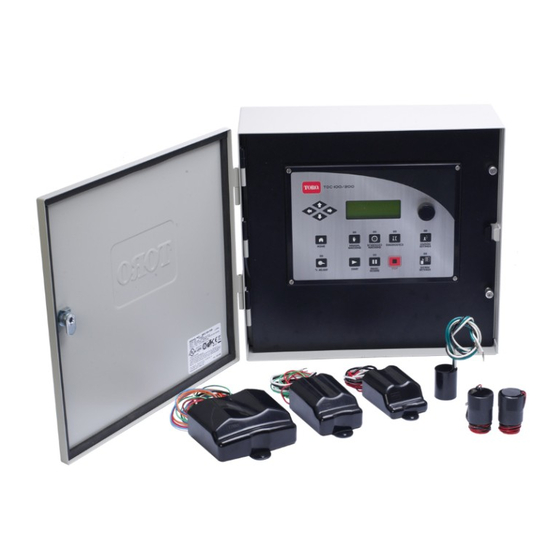
CHAPTER 1: TDC+ CONTROL MODULE OVERVIEW Your TDC+ Controller Interface has three main elements to use throughout the programming process. These are: Display Navigation Keys Keypad Programming as covered in this User’s Guide will be through the Keypad, Navigation Keys, Display, and Central Software. TDC+ QUICK START GUIDE Page 2 / 20 ... - Page 3 USER INTERFACE OVERVIEW (KEYPAD & DISPLAY) TDC+ Control Module Keypad The TDC+ Control Module has 24 button keys for use as the programming interface: This keypad includes numeric buttons 1 – 9 and 0 used for numeric data entry. Also used in programming and operations are: ON/YES & OFF/NO Keys Used for manual operations as well as entering ON / OFF or YES / NO in programming. ESC (Escape) Key Used for exiting menus or Edit Mode and returning to normal operations (default screen) ENTER Key Used for functions like entering a selected submenu or saving information. Arrow (Navigation) Keys Used for navigating in Menus, Submenus, and Edit Modes, as well an incrementing values in programming. SCHEDULE / PROGRAM Used for selecting Program Groups or GROUP Key Schedules (run days) when programming. PROGRAM NUMBER This button will be described in more detail in Key later pars of this guide. Used for selecting the Program (1‐4) associated with a Program Group ...
- Page 4 TDC+ Control Module Display The TDC+ Controller has a two‐line LCD for display of information. When you first walk up to your Sentinel controller, the display should be in its standard mode showing current time, day, week (of schedule), actual flow (if anything running) and expected flow. This display should look something like the following: Default Display Upper Line Lower Line Time – 07:18 P (7:18 PM) Actual Flow – 00000 (0 GPM) Day – MO (Monday) Expected Flow – 00000 (0 GPM) Week (of schedule) – W1 (Week 1) Flow Status – No current flow Sensor – No current sensor indication indicator Remote – L (Locked) Alarm Status – A (Alarm Exists) The standard indicators in the display are as follows: TIME HH:MM Hours : Minutes (12‐hour format) A or P AM or PM DAY SU, MO, Two‐letter Designation of Day of Week TU, WE, TH, FR, SA, or SU WEEK W1 to W6 ...
-
Page 5: Main Menu & Submenus
PROGRAMMING OVERVIEW & NAVIGATION Main Menu & Submenus The TDC+ Controller is programmed by navigating through a Main Menu which includes seven options: Operations, Utility, Alarms, Flow, Schedule Data, Program Data, and Zone/ET Data. Each of these Main Menu options has a Submenu for entering and changing data. This structure is detailed below as well as being shown on the Program Instructions Card on the control module itself. MENU SUBMENU To Select • • Manual All Manuals Off • • OPERATIONS Auto Slot / Station All Autos Off • • Rain Off Days Station Days Off • • Time & Day Program Clear • • Day Change Hour N/O Master UTILITY ... - Page 6 Navigation The controller normal mode (default) screen looks like: • To enter the Main Menu from this default screen, you need to hit any of the arrow keys on the keypad: This will bring up the OPERATIONS option of the Main menu. • To navigate through the Main Menu, use the right or left arrow keys. • To enter a submenu for any of the Main menu options, use the up or down arrow keys. • When the desired submenu is reached, press the enter key to view or change data in the submenu. IMPORTANT: When entering data into one of the submenus, the controller is in the Edit Mode. The controller will not begin any scheduled operation until you have exited the Edit Mode. Programs that are running prior to entering the Edit Mode will continue running. Any time you enter or change any data, you must press the ENTER key to save the data. Otherwise, the newly entered data will not be saved. To exit the Edit Mode, press the ESC (Escape) key once or twice as necessary to return to normal mode (default) screen. If you forget to press the ESC key, the controller will automatically revert to normal mode after two minutes. TDC+ QUICK START GUIDE Page 6 / 20 ...
-
Page 7: Chapter 2: Quick Start Steps
CHAPTER 2: QUICK START STEPS This guide is designed to show you the minimum initial steps to program a TDC+ controller using the Sentinel Lite software so irrigation occurs. The primary steps we will be following in the quick start process are: Where Section Function Action Controller UTILITY Menu Unit Code Set Unit Code Software SETUP Database Create New Database Software MANAGE Master List Create Unit Software – Satellite Setup Directory Special Data – Comm Settings Setup Communications Method Software – Satellite Setup Directory Special Data – General Receive Satellite Firmware Software – Satellite Setup Directory Time & Day Synchronize Time Software – Satellite Setup Directory ... - Page 8 SOFTWARE & DATABASE SETUP 1. Verify that Sentinel Lite is properly installed on your computer. 2. Double Click on the Sentinel Icon (identified as a Red Clock) on your desktop to open the Sentinel Lite interface. Note: Be patient, Sentinel opens slowly. If you double again, you will open a second application –...
- Page 9 UNIT CREATION You must now create your Field Units in the Sentinel Software. 1. Left Click on MANAGE in the left hand side of the upper tool bar. 2. In the Manage Window, click “+” (Plus Sign) on the right hand side under Master List (all units in database).
-
Page 10: Unit Connection
UNIT CONNECTION These steps indicate how to direct-connect your computer to your TDC+ Control Module. 1. Identify Serial Comm Port location (9 pin male connection) on your computer 2. If there are no Comm Ports then use a USB connection (requires a USB to 9 pin adapter – (can be purchased at local electronics store) 3. -
Page 11: Unit Setup
UNIT SETUP 1. Go to the Left Side Navigation Tree, Satellites Tab. 2. Click on the Satellite Unit just created. This should expand the unit menu tree. 3. Under the Setup Directory, click on Special Data. Note: When the Special Data window opens you will see it opens on the “General” Tab and that the Controller Firmware Version is grayed out. - Page 12 Receiving Satellite Firmware Version This procedure will establish two-way communications as well as ensure that the Sentinel WMS software will function properly with the current satellite firmware version. 1. Choose the General tab. The Firmware Version and Checksum data fields will be blank. 2.
- Page 13 “front” serial port, because computer programming occurs through the “back port”. 8. Choose the Advanced tab. 9. Under Station Type / port assignments: For “Send Toro 2-Wire commands to:” select Serial Port 1 (front port). 10. Under “Station Types allowed after 96,” select Toro 2-wire.
- Page 14 TIME & DAY SETUP Both the PC running the Sentinel WMS software and the satellite controllers have time-keeping registers that must remain synchronized at all times to maintain scheduled operations. The Time & Day window provides setup options for the time/day synchronization feature. 1.
- Page 15 You can enter a Type and Description for each station to aid identification, but it is not required. 2. On the Top of Zone Data Select Setup Toro 2-Wire. This sets all stations as Toro 2-Wire stations. For Each Two-Wire Station 3.
-
Page 16: Start Times
PROGRAMMING FOR AUTOMATIC OPERATIONS 1. Click the Automatic Operations under the Programming directory to open the Automatic Operations Window. Note: Each satellite is capable of having 16 individual irrigation programs. The programs are organized in groups of four, called Clusters, with four programs assigned to each Cluster. Clusters are identified as A, B C, and D. -
Page 17: Station Run Times
Watering Days (Schedule) Up to 16 unique watering day schedules can be defined. For identification, each schedule has a number assignment ranging from 1–16. To assign the program to one of the schedules, simply enter or scroll to the corresponding number in the “Selected Schedule” box. 1. - Page 18 Additional Program Parameters The various settings within this portion of the Program window enable each program to be modified as needed for optimum control. As settings are made, the program setup status information will be displayed in the colored panel. Green and Blue indicate the selected parameters are acceptable.
-
Page 19: Chapter 3: Setup Check & Troubleshooting
If it was off, turn it on, and power down the Sentinel and Gateway, wait 30 seconds, and power back up. 4. Each station must be set up in zone data, use the Setup Toro 2-wire button on the top of the zone data screen to set station types and view instructions. You will be setting station type, decoder address, decoder station, and daughter board number for each station. - Page 20 MIMINUM RECOMMENDED VERSIONS: Sentinel WMS Software: 3.1.0.9 and later TDC+ Control Module Firmware: Version 2.46 Checksum ba47 or Version 2.46 Checksum 22D5 Version 2.47 (any Checksum) and up TDC+ QUICK START GUIDE Page 20 / 20 ...
Need help?
Do you have a question about the TDC+ and is the answer not in the manual?
Questions and answers