Table of Contents
Advertisement
Quick Links
Advertisement
Table of Contents

Related Manuals for Panasonic MC-E4051-00


Summary of Contents for Panasonic MC-E4051-00
-
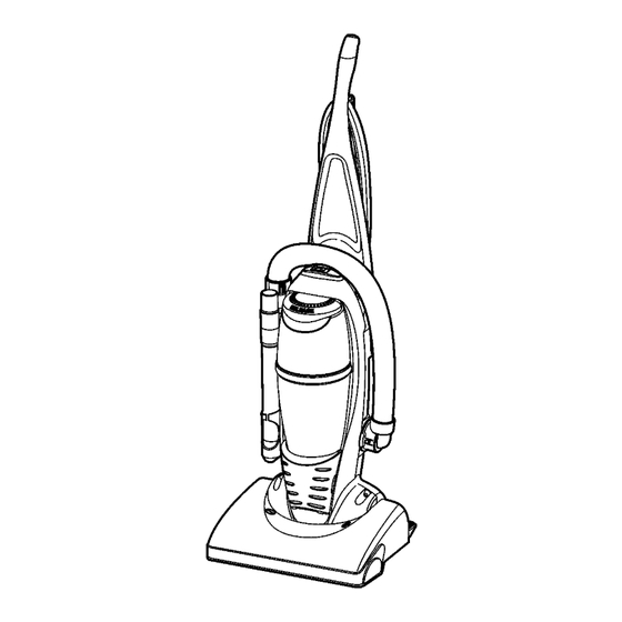
Page 1: Vacuum Cleaner
Order Number MAC0418001C2 Vacuum Cleaner MC-E4051-00 Specifications are subject to change without notice for further improvement. Matsushita Electric Industrial Co., Ltd All rights reserved. Unauthorized copying and distribution is a violation of law. -
Page 2: Wire Management Drawing
Wire Management Drawing 1.2. NOTE: For general servicing, it is necessary to eliminate pinching of any wire during reassembly. After servicing any electrical compo- nent or electrical enclosure, the unit should be reassembled and checked for dielectric breakdown or current leakage. -
Page 3: Replacement Instructions
3 REPLACEMENT INSTRUCTIONS 3.1. Nozzle cover 3.2. Beater Bar Assembly Replacement 3.1.1. Removal 1. Release the nozzle cover by rotating the nozzle cover retainers to the UNLOCK position. 2. Rotate upward on the nozzle cover to remove it from the nozzle base. -
Page 4: Belt Replacement
3.5. Handle Release Assembly 4. Insert the beater bar by placing the rounded portion of the end caps down into the slots in the nozzle base. Replacement 5. Press firmly, checking to see that each end is completely inserted. 3.5.1. Removal 1. -
Page 5: Motor Protector Replacement
3.6. Mains Lead Assembly Replace- 3.7. ON/OFF Switch Replacement ment 3.7.1. Removal 1. Remove the dust cover to expose the electrical connec- 3.6.1. Removal tions of the ON/OFF switch. 1. Refer to Handle Assembly Replacement Section. 2. With handle removed from body disassemble handle by removing fourteen (14) screws. - Page 6 3.9. Motor Assembly Replacement 3.9.1. Removal 1. Remove the dust cover by removing the eight (8) screws. 2. Remove the lower plate, beater bar assembly, belt, the plastic shaft and the nozzle housing as instructed in the respective removal sections. 3.
Need help?
Do you have a question about the MC-E4051-00 and is the answer not in the manual?
Questions and answers