Yamaha F6A Owner's Manual
Hide thumbs
Also See for F6A:
- Owner's manual (244 pages) ,
- Owner's manual (100 pages) ,
- Owner's manual (206 pages)

Subscribe to Our Youtube Channel
Related Manuals for Yamaha F6A


Summary of Contents for Yamaha F6A
- Page 1 FT8D OWNER’S MANUAL Read this manual carefully before operating this outboard motor. 60R-F8199-74-E0...
- Page 2 Read this manual carefully before operating this outboard motor. Keep this manual onboard in a waterproof bag when boating. This manual should stay with the outboard motor if it is sold.
-
Page 3: Important Manual Information
If there is any To the owner question concerning this manual, please con- Thank you for choosing a Yamaha outboard sult your Yamaha dealer. motor. This Owner’s Manual contains infor- To ensure long product life, Yamaha recom-... -
Page 4: Table Of Contents
Table of contents Safety information......1 Propeller selection ......13 Outboard motor safety ....1 Start-in-gear protection ....14 Engine oil requirements ....14 Propeller ..........1 Rotating parts ........1 Fuel requirements ......15 Hot parts..........1 Gasoline ........... 15 Electric shock ........ - Page 5 Table of contents Alert indicator ........26 Shifting .......... 42 Instruments and indicators .... 27 Stopping boat........ 44 Indicators........27 Stopping engine ......44 Low oil pressure-alert indicator ..27 Procedure......... 44 Engine control system....28 Procedure......... 45 Alert system ........28 Trimming outboard motor....
- Page 6 Table of contents Changing engine oil......65 Checking wiring and connectors ..67 Checking propeller ......67 Removing propeller ......67 Installing propeller ......68 Changing gear oil ......69 Cleaning fuel tank......70 Inspecting and replacing anode(s) ... 71 Checking battery (for electric start models) .........
-
Page 7: Safety Information
Safety information EMU33622 EMU34790 Outboard motor safety Power tilt Body parts can be crushed between the mo- Observe these precautions at all times. tor and the clamp bracket when the motor is EMU36500 Propeller trimmed or tilted. Keep body parts out of this People can be injured or killed if they come in area at all times. -
Page 8: Gasoline Exposure And Spills
Have an approved personal flotation device distribution can compromise the boats han- (PFD) on board for every occupant. Yamaha dling and lead to an accident, capsizing or recommends that you must wear a PFD swamping. whenever boating. At a minimum, children... -
Page 9: Avoid Collisions
Safety information EMU33771 EMU33880 Avoid collisions Passenger training Scan constantly for people, objects, and oth- Make sure at least one other passenger is er boats. Be alert for conditions that limit your trained to operate the boat in the event of an visibility or block your vision of others. -
Page 10: General Information
Record your outboard motor serial number in the spaces provided to assist you in ordering spare parts from your Yamaha dealer or for reference in case your outboard motor is sto- len. EMU25190... -
Page 11: Ce Marking
General information Product code of model (Approved model code) Code of conformed directives EMU25203 CE Marking Outboard motors affixed with this “CE”mark- ing conform with the directives of; 98/37/EC, 94/25/EC - 2003/44/EC and 2004/108/EC. 1. CE marking location 1. CE marking location ZMU06304... -
Page 12: Read Manuals And Labels
Read any manuals supplied with the boat. Read all labels on the outboard motor and the boat. If you need any additional information, contact your Yamaha dealer. EMU33831 Warning labels If these labels are damaged or missing, contact your Yamaha dealer for replacements. F6AMH, F8CMH, FT8DMH... - Page 13 General information FT8DE, FT8DEP...
- Page 14 General information ZMU05706 EMU33912 Contents of labels EWM01671 The above warning labels mean as follows. WARNING Read Owner’s Manuals and labels. EWM01691 Wear an approved personal flotation de- WARNING vice (PFD). Emergency starting does not have start- Attach engine shut-off cord (lanyard) to in-gear protection.
- Page 15 General information EMU33843 Electrical hazard Symbols The following symbols mean as follows. Notice/Warning ZMU05666 Remote control lever/gear shift lever operat- ing direction, dual direction ZMU05696 Read Owner’s Manual ZMU05667 Engine start/ Engine cranking ZMU05664 Hazard caused by continuous rotation ZMU05668 ZMU05665...
-
Page 16: Specifications And Requirements
Specifications and requirements EMU34520 Transom height S: Specifications F6AMH 435 mm (17.1 in) TIP: F8CMH 435 mm (17.1 in) “(AL)” stated in the specification data below Transom height L: represents the numerical value for the alumi- F6AMH 562 mm (22.1 in) num propeller installed. - Page 17 Specifications and requirements Maximum output: Valve clearance (cold engine) IN: F6AMH 4.4 kW@5000 r/min (6 0.15–0.20 mm (0.0059–0.0079 in) HP@5000 r/min) Valve clearance (cold engine) EX: F8CMH 5.9 kW@5500 r/min (8 0.20–0.25 mm (0.0079–0.0098 in) HP@5500 r/min) Min. cold cranking amps (CCA/EN): FT8DE 5.9 kW@5500 r/min (8 FT8DE 347.0 A HP@5500 r/min)
-
Page 18: Installation Requirements
Specifications and requirements Recommended engine oil: Noise and vibration level: 4-stroke outboard motor oil Operator sound pressure level (ICOMIA Recommended engine oil group 1*: 39/94 and 40/94): SAE 10W-30/10W-40/5W-30 77.0 dB(A) API SE/SF/SG/SH/SJ/SL Vibration on tiller handle (ICOMIA 38/94): Recommended engine oil group 2*: Vibration on tiller handle is under 2.5 SAE 15W-40/20W-40/20W-50 m/s²... -
Page 19: Remote Control Requirements
18 volts or device prevents the engine from starting un- higher with the above models. Consult your less it is in neutral. Yamaha dealer for details on installing an op- EMU25694 Battery requirements tional Rectifier Regulator. -
Page 20: Start-In-Gear Protection
1. Propeller diameter in inches 2. Propeller pitch in inches 3. Type of propeller (propeller mark) EMU25760 Start-in-gear protection Yamaha outboard motors affixed with the pic- tured label or Yamaha-approved remote con- trol units are equipped with start-in-gear protection device(s). This feature permits the... -
Page 21: Fuel Requirements
EMU36880 Muddy or acidic water clip. Spare parts, such as an extra set of spark Yamaha strongly recommends that you have plugs. your dealer install the optional chromium-plat- ed water pump kit if you use the outboard mo- Consult your Yamaha dealer for details. -
Page 22: Emission Control Information
Engines affixed with the label pictured below conform to SAV (the Swiss exhaust emission regulations for Swiss inshore waters). ZMU04494 Approval label of emission control certifi- cate 1. Approval label location YAMAHA MOTOR CO.,LTD. Motorfamilie Abgastypenpruf- Nummer ZMU04492 Fuel requirement label 1. Fuel requirement label location... -
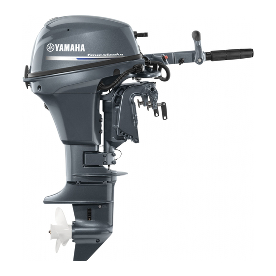
Page 23: Components
Components EMU2579J Components diagram TIP: * May not be exactly as shown; also may not be included as standard equipment on all models. F6A, F8C 1. Top cowling 17.Throttle grip 2. Top cowling lock lever 18.Throttle friction adjuster 3. Anti-cavitation plate 19.Tilt lock lever... -
Page 24: Fuel Tank
Components FT8D 1. Top cowling 22.Remote control box (side mount type)* 2. Top cowling lock lever 23.Fuel tank 3. Anti-cavitation plate EMU25802 Fuel tank 4. Propeller If your model was equipped with a portable 5. Cooling water inlet 6. Drain screw fuel tank, its function is as follows. -
Page 25: Fuel Joint
Components ZMU01992 1. Power tilt switch 1. Air vent screw 2. Remote control lever 2. Fuel gauge 3. Neutral interlock trigger 3. Fuel joint 4. Neutral throttle lever 4. Fuel tank cap 5. Main switch / choke switch EMU25830 Fuel joint 6. -
Page 26: Neutral Interlock Trigger
Components EMU26201 EMU26221 Neutral interlock trigger Choke switch To shift out of neutral, first pull the neutral in- To activate the choke system, press in the terlock trigger up. main switch while the key is turned to the “ ” (on) or “... -
Page 27: Throttle Grip
Components EMU25961 Throttle indicator The fuel consumption curve on the throttle in- dicator shows the relative amount of fuel con- sumed for each throttle position. Choose the setting that offers the best performance and fuel economy for the desired operation. 1. -
Page 28: Engine Shut-Off Cord (Lanyard) And Clip
Components the loss of most steering control. Also, without engine power, the boat could slow rapidly. This could cause people and ob- jects in the boat to be thrown forward. [EWM00122] 1. Cord 2. Clip 3. Engine shut-off switch When constant speed is desired, tighten the adjuster to maintain the desired throttle set- ting. -
Page 29: Engine Stop Button
Components EMU26070 2. Clip Manual starter handle 3. Engine shut-off switch To start the engine, first gently pull the handle EMU26001 out until resistance is felt. From that position, Engine stop button then pull the handle straight out quickly to To open the ignition circuit and stop the en- crank the engine. -
Page 30: Power Tilt Switch
Components To increase resistance, turn the adjuster EMU26102 Power tilt switch clockwise. The power tilt system adjusts the outboard To decrease resistance, turn the adjuster motor angle in relation to the transom. Push- counterclockwise. ing the switch “ ” (up) tilts the outboard mo- EWM00040 tor up. -
Page 31: Tilt Support Knob
Components 1. Tilt lock lever ECM01660 NOTICE To lock it, set the tilt lock lever in the lock po- sition. To release, push the tilt lock lever in the Do not use the tilt support bar when traile- release position. ring the boat. -
Page 32: Top Cowling Lock Lever (Pull Up Type)
Components ECM00660 NOTICE Do not use the tilt support lever or knob when trailering the boat. The outboard mo- tor could shake loose from the tilt support and fall. If the motor cannot be trailered in the normal running position, use an addi- tional support device to secure it in the tilt position. -
Page 33: Instruments And Indicators
Instruments and indicators EMU36014 Indicators EMU36023 Low oil pressure-alert indicator If oil pressure drops too low, this indicator will light up. For further information, see page 28. ECM00022 NOTICE Do not continue to run the engine if the low oil pressure-alert indicator is on and the engine oil level is lower. -
Page 34: Engine Control System
ECM00091 NOTICE Do not continue to operate the engine if a alert device has activated. Consult your Yamaha dealer if the problem cannot be lo- cated and corrected. EMU3016A Low oil pressure alert If the oil pressure drops too low, the alert de- vice will activate. -
Page 35: Installation
Installation EMU26902 Installation The information presented in this section is in- tended as reference only. It is not possible to provide complete instructions for every possi- ble boat and motor combination. Proper mounting depends in part on experience and the specific boat and motor combination. EWM01590 WARNING ZMU01760... -
Page 36: Clamping The Outboard Motor
Consult your Yamaha dealer or boat manufacturer for further information on determining the prop- er mounting height. For instructions on setting the trim angle of the outboard motor, see page 45. - Page 37 Installation your Yamaha dealer. WARNING! Avoid using bolts, nuts or washers other than those contained in the engine packaging. If used, they must be of at least the same quality of material and strength and must be tightened se- curely. After tightening, test run the engine and check their tightness.
-
Page 38: Operation
Operation EMU36380 TIP: First-time operation Failure to follow the break-in procedure could EMU36390 Fill engine oil result in reduced engine life or even severe The engine is shipped from the factory without engine damage. Run the engine in the water, engine oil. -
Page 39: Fuel Level
Operation ECM00120 If any fuel leakage is found, the fuel sys- NOTICE tem must be repaired by a qualified me- Do not start the engine out of water. Over- chanic. Improper repairs can make the heating and serious engine damage can outboard unsafe to operate. -
Page 40: Engine Oil
Operation EMU27165 Engine oil Put the outboard motor in an upright po- sition (not tilted). NOTICE: If the motor is not level, the oil level indicated on the dipstick may not be accurate. [ECM01790] Remove the top cowling. Remove oil dipstick and wipe it clean. Insert the dipstick and remove it again. -
Page 41: Engine
If the overheat during operation. [ECM01800] top cowling is loose, have it repaired by your Yamaha dealer. 1. Fitting 2. Flushing device EMU34782 Checking power tilt system... -
Page 42: Battery
Operation a lot of gasoline vapor, or get some gas- oline in your eyes, see your doctor im- mediately. If gasoline spills on your skin, wash with soap and water. If gaso- line spills on your clothing, change your clothes. Stop the engine. -
Page 43: Operating Engine
Operation EMU27451 Operating engine EMU27464 Feeding fuel (portable tank) EWM00420 WARNING Before starting the engine, make sure that the boat is tightly moored and that you can steer clear of any obstructions. Be sure there are no swimmers in the water near you. -
Page 44: Starting Engine
Operation EMU27492 Starting engine EWM01600 WARNING Before starting the engine, make sure that the boat is tightly moored and that you can steer clear of any obstructions. Be sure there are no swimmers in the water near you. EMU27508 Manual start models (tiller control) TIP: EWM01840 WARNING... - Page 45 Operation Pull out / turn the choke knob fully. After After the engine starts, slowly return the the engine starts, replace / return the manual starter handle to its original posi- knob to the home position. tion before releasing it. Slowly return the throttle grip to the fully closed position.
- Page 46 Operation EMU27645 Electric start / remote control models EWM01840 WARNING Failure to attached engine shut-off cord could result in a runaway boat if opera- tor is ejected. Attach the engine shut-off cord to a secure place on your clothing, or your arm or leg while operating. Do not attach the cord to clothing that could tear loose.
-
Page 47: Checks After Starting Engine
5 seconds. occur. Stop the engine and check whether the cooling water inlet on the lower case or the cooling water pilot hole is blocked. Consult your Yamaha dealer if the prob- lem cannot be located and corrected. -
Page 48: Warming Up Engine
Pull the neutral interlock trigger up (if stop the engine. Otherwise serious equipped). engine damage could occur. Check the oil level and add oil if necessary. Consult your Yamaha dealer if the cause for the low oil pressure-alert in- dicator cannot be found. [ECM01830] EMU36530... - Page 49 Operation that the tilt lock lever is in the lock/down position (if equipped) before operating in reverse. To shift from in gear (forward/reverse) to neu- tral Close the throttle so that the engine slows to idle speed. ZMU02030 After the engine is at idle speed in gear move the remote control lever / gear shift lever firmly and crisply into the neutral po- sition.
-
Page 50: Stopping Boat
Operation Do not shift into reverse while traveling at planing speeds. Loss of control, boat swamping, or damage to the boat could occur. The boat is not equipped with a separate braking system. Water resistance stops it af- ter the throttle lever is moved back to idle. The stopping distance varies depending on gross weight, water surface conditions, and wind di- rection. -
Page 51: Procedure
Operation After stopping the engine, tighten the air vent screw on the fuel tank cap and set the fuel cock lever or knob to the closed position, if equipped. After stopping the engine, disconnect the fuel line or close the fuel cock if there is a fuel joint or a fuel cock on the boat. -
Page 52: Adjusting Trim Angle For Manual Tilt Models
Operation engine, and propeller. Correct trim is also af- fected by variables such as the load in the boat, sea conditions, and running speed. 1. Trim rod Reposition the rod in the desired hole. To raise the bow (“trim-out”), move the rod away from the transom. -
Page 53: Adjusting Trim Angle (Power Tilt Models)
Operation EMU27904 Make test runs with the trim set to different an- Adjusting trim angle (power tilt mod- gles to find the position that works best for els) your boat and operating conditions. EWM00753 EMU27911 WARNING Adjusting boat trim Be sure all people are clear of the out- When the boat is on plane, a bow-up attitude board motor when adjusting the trim an- results in less drag, greater stability and effi-... -
Page 54: Tilting Up And Down
Operation EWM00221 WARNING Be sure all people are clear of the out- board motor when tilting up and down, Body parts can be crushed between the motor and the clamp bracket when the mo- tor is trimmed or tilted. EWM00250 WARNING Leaking fuel is a fire hazard. -
Page 55: Procedure For Tilting Up (Power Tilt Models)
Operation board motor could shake loose from the tilt support and fall. If the motor cannot be trailered in the normal run- ning position, use an additional sup- port device to secure it in the tilt position. For more detailed informa- tion, see page 54. -
Page 56: Procedure For Tilting Down (Manual Tilt Models)
Operation tilt switch / power tilt switch “ ” (down) to retract the trim rods. NOTICE: Be sure to retract the trim rods completely dur- ing mooring. This protects the rods from marine growth and corrosion which could damage the power trim and tilt mechanism. -
Page 57: Shallow Water
Operation Use extra care when operating in re- verse. Too much reverse thrust can cause the outboard motor to lift out of the water, increasing the chance of acci- dent and personal injury. ECM00260 NOTICE Do not tilt the outboard motor up so that the cooling water inlet on the lower unit is above the surface of the water when set- Push the power tilt switch “... -
Page 58: Power Tilt Models
Operation To return the outboard motor to the nor- mal running position, place the remote control lever / gear shift lever in neutral. Place the tilt lock lever in the lock/down position, then slightly tilt the outboard mo- tor up until the tilt support bar automati- cally returns to the free position. -
Page 59: Cruising In Other Conditions
Place the remote control lever in neutral. the cowling. Cruising in muddy, turbid, or acidic water Yamaha strongly recommends that you use the optional chromium-plated water pump kit (see page 15) if you use the outboard motor in acidic water or water with a lot of sediment in it, such as muddy or turbid (cloudy) water. -
Page 60: Maintenance
It is advisable to have your outboard motor then trailer the outboard motor in the tilt posi- serviced by an authorized Yamaha dealer pri- tion using a motor support device such as a or to storage. However, you, the owner, with a transom saver bar. -
Page 61: Procedure
Maintenance ECM01080 is below the level of the anti-cavitation NOTICE plate, or if the water supply is insuffi- To prevent problems which can be cient, engine seizure may occur. caused by oil entering the cylinder from [ECM00291] the sump, keep the outboard motor in the attitude shown when transporting and storing it. -
Page 62: Lubrication
69. Inspect the oil for the presence of water that indicates a leaky seal. Seal replacement should be performed by an authorized Yamaha dealer prior to use. Grease all grease fittings. For further de- tails, see page 62. TIP: For long-term storage, fogging the engine 1. -
Page 63: Cleaning The Outboard Motor
Always completely reassemble the mo- tor before operation. ZMU02052 EMU28511 Replacement parts TIP: If replacement parts are necessary, use only For cooling system flushing instructions, see genuine Yamaha parts or parts of equivalent page 54. design and quality. Any part of inferior quality... -
Page 64: Severe Operating Conditions
Maintenance may malfunction, and the resulting loss of control could endanger the operator and pas- sengers. Yamaha genuine parts and acces- sories are available from your Yamaha dealer. EMU34150 Severe operating conditions Severe operating conditions involve one or more of the following types of operation on a... -
Page 65: Maintenance Chart 1
When operating in salt water, muddy, other turbid (cloudy), acidic water, the engine should be flushed with clean water after each use. The “ ” symbol indicates the check-ups which you may carry out yourself. The “ ” symbol indicates work to be carried out by your Yamaha dealer. Initial Every Item Actions... - Page 66 Maintenance Initial Every Item Actions 20 hours 100 hours 300 hours 500 hours (3 months) (1 year) (3 years) (5 years) Fuel line(High pres- Inspection sure) Fuel line(High pres- Inspection or replace- sure) ment as necessary Fuel line(Low pres- Inspection sure) Fuel line(Low pres- Inspection or replace-...
-
Page 67: Maintenance Chart 2
(1 year) (3 years) (5 years) Wire harness connec- Inspection or replace- tions/Wire coupler con- ment as necessary nections Inspection and clean- (Yamaha) Fuel tank ing as necessary EMU34451 Maintenance chart 2 Every Item Actions 1000 hours Guide exhaust/ex- Inspection or replace-... -
Page 68: Greasing
Maintenance EMU28941 Greasing Yamaha grease A (water resistant grease) Yamaha grease D (corrosion resistant grease; for propeller shaft) F6A, F8C... - Page 69 Maintenance FT8D...
-
Page 70: Cleaning And Adjusting Spark Plug
Do not attempt to di- agnose any problems yourself. Instead, take the outboard motor to a Yamaha dealer. You 1. Spark plug gap should periodically remove and inspect the 2. -
Page 71: Inspecting Idling Speed
Then remove the oil filler cap. adjustment, consult a Yamaha dealer or other Let the oil drain completely. Wipe up any qualified mechanic. - Page 72 If a torque wrench is not available when you severe engine damage. Consult your are installing the drain screw, finger tighten Yamaha dealer if the problem cannot the screw just until the gasket comes into con- be located and corrected.
-
Page 73: Checking Wiring And Connectors
Maintenance TIP: For more information on the disposal of used oil, consult your Yamaha dealer. Change the oil more often when operating the engine under adverse conditions such as extended trolling. EMU29112 Checking wiring and connectors Check that each grounding wire is properly secured. -
Page 74: Installing Propeller
Maintenance Apply Yamaha marine grease or a corro- sion resistant grease to the propeller shaft. Install the spacer (if equipped), thrust washer, washer (if equipped), and pro- peller on the propeller shaft. NOTICE: Be sure to install the thrust washer before... -
Page 75: Changing Gear Oil
You could be severely injured if which can cause gear damage. Con- the outboard motor falls on you. sult a Yamaha dealer for repair of the Never get under the lower unit while it is lower unit seals. [ECM00711]... -
Page 76: Cleaning Fuel Tank
If you have any question about properly ZMU03231 doing this procedure, consult your Remove the screws holding the fuel joint Yamaha dealer. assembly. Pull the assembly out of the Keep away from sparks, cigarettes, tank. flames, or other sources of ignition when cleaning the fuel tank. -
Page 77: Inspecting And Replacing Anode(S)
NOTICE Do not paint anodes, as this would render them ineffective. TIP: Inspect ground leads attached to external an- odes on equipped models. Consult a Yamaha EMU29322 Checking battery (for electric start dealer for inspection and replacement of inter- models) nal anodes attached to the power unit. -
Page 78: Connecting The Battery
If the battery needs charging, 1. Red cable consult your Yamaha dealer. 2. Black cable 3. Battery Check the battery connections. They should be clean, secure, and covered by The electrical contacts of the battery and an insulating cover. -
Page 79: Disconnecting The Battery
Maintenance EMU29371 Disconnecting the battery Turn off the battery cut-off switch (if equipped) and main switch. NOTICE: If they are left on, the electrical system can be damaged. [ECM01930] Disconnect the negative cable(s) from the negative (-) terminal. NOTICE: Al- ways disconnect all negative (-) ca- bles first to avoid a short circuit and damage to the electrical system. -
Page 80: Trouble Recovery
Yamaha outboard motors. Therefore Q. Has fuel pump malfunctioned? some items may not apply to your model. A. Have serviced by a Yamaha dealer. If your outboard motor requires repair, bring it to your Yamaha dealer. Q. Are spark plug(s) fouled or of incorrect... - Page 81 A. Return to normal operating position. A. Fill tank with clean, fresh fuel. Q. Is carburetor clogged? Q. Is fuel filter clogged? A. Have serviced by a Yamaha dealer. A. Clean or replace filter. Q. Is fuel joint connection incorrect? Q. Have ignition parts failed? A.
- Page 82 Q. Is fuel system obstructed? Q. Is water pump or thermostat faulty? A. Check for pinched or kinked fuel line or oth- A. Have serviced by a Yamaha dealer. er obstructions in fuel system. Q. Is there excess water in fuel filter cup? Q.
-
Page 83: Temporary Action In Emergency
Substituting an incorrect fuse or a piece of Q. Is steering pivot loose or damaged? wire could allow excessive current flow. A. Tighten or have serviced by a Yamaha This could cause electric system damage dealer. and a fire hazard. -
Page 84: Power Tilt Will Not Operate
Trouble Recovery EWM01022 WARNING Use this procedure only in an emergen- cy to return to the nearest port for re- pairs. When the emergency starter rope is used to start the engine, the start-in- gear protection device does not operate. Make sure the remote control lever is in neutral. -
Page 85: Emergency Starting Engine
Trouble Recovery Do not touch the ignition coil, spark plug wire, spark plug cap, or other electrical components when starting or operating the motor. You could get an electrical shock. EMU29562 Emergency starting engine Remove the top cowling. Remove the start-in-gear protection ca- ZMU01880 ble from the starter, if equipped. -
Page 86: Engine Fails To Operate
[ECM00381] 1. Yellow cord EMU33501 Treatment of submerged motor If the outboard motor is submerged, immedi- ately take it to a Yamaha dealer. Otherwise some corrosion may begin almost immediate-... - Page 88 YAMAHA MOTOR CO., LTD. Printed in France April 2008–0.3 × 1 CR...
Need help?
Do you have a question about the F6A and is the answer not in the manual?
Questions and answers