Table of Contents
Advertisement
Quick Links
Form No. 3357-361 Rev. B
Safety • Assembly • Operation • Tips & Techniques • Maintenance • Troubleshooting • Parts Lists • Warranty
OPERATOR'S MANUAL
Model
OEM-190-032
190-032-101
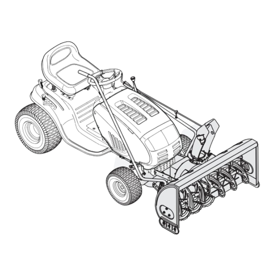
42-inch Two-Stage Snow Thrower Attachment
For FastAttach
Compatible Lawn Tractors & Garden Tractors
™
IMPORTANT
READ SAFETY RULES AND INSTRUCTIONS CAREFULLY BEFORE OPERATION
Warning: This unit is equipped with an internal combustion engine and should not be used on or near any unimproved forest-covered, brush-
covered or grass-covered land unless the engine's exhaust system is equipped with a spark arrester meeting applicable local or state laws (if any).
If a spark arrester is used, it should be maintained in effective working order by the operator. In the State of California the above is required by law
(Section 4442 of the California Public Resources Code). Other states may have similar laws. Federal laws apply on federal lands. A spark arrester
for the muffler is available through your nearest engine authorized service dealer or contact the service department, P.O. Box 361131 Cleveland,
Ohio 44136-0019.
FORM NO. 769-01933C
3/8/2006
PRINTED IN U.S.A.
MTD LLC, P.O. BOX 361131 CLEVELAND, OHIO 44136-0019
Advertisement
Table of Contents

Related Manuals for MTD 190-032-10


Summary of Contents for MTD 190-032-10
- Page 1 (Section 4442 of the California Public Resources Code). Other states may have similar laws. Federal laws apply on federal lands. A spark arrester for the muffler is available through your nearest engine authorized service dealer or contact the service department, P.O. Box 361131 Cleveland, Ohio 44136-0019. FORM NO. 769-01933C 3/8/2006 PRINTED IN U.S.A. MTD LLC, P.O. BOX 361131 CLEVELAND, OHIO 44136-0019...
-
Page 2: Table Of Contents
This Operator’s Manual is an important part of your snow thrower attachment. It will help you assemble, prepare and maintain the unit for best performance. Please read and understand what it says. TABLE OF CONTENTS 1. Rider Model Identification ........ Page 3 9. -
Page 3: Rider Model Identification
FastAttach Snow ™ Model Plate Thrower Attachment NOTE: This Operator’s Manual covers several models. Snow thrower hook-up instructions vary by model. Not Rider Model all features discussed in this manual are applicable to all snow thrower attachments. Identification To The Owner Model OEM-190-032 42-inch two-stage snow thrower attachment is designed for use on FastAttach™... - Page 4 WARNING: Engine Exhaust, some of its constituents, and certain vehicle compo- nents contain or emit chemicals known to State of California to cause cancer and birth defects or other reproductive harm. DANGER: This machine was built to be operated according to the rules for safe operation in this manual.
- Page 5 Operation Maintenance & Storage 1. Do not put hands or feet near rotating parts, in the 1. Never tamper with safety devices. Check their proper auger/impeller housing or chute assembly. Contact with the operation regularly. Refer to the maintenance and adjust- rotating parts can amputate hands and feet.
-
Page 6: Carton Contents
Cotter Pin retailer where you purchased this unit, Assembly Brackets & Hardware call MTD directly at Chute Directional 1-330-220-4MTD or Support w/ Tilt Lever toll free at & Upper Crank Rod 1-800-800-7310. Undercarriage Assembly... - Page 7 • Left & Right Assembly Brackets (683-04215 & 683-04214) & Hardware (710-0514 Hex Screw, 712-04065 purchased this unit, Flange Nut, 738-0143 Shoulder Screw & 712-04063 Flange Nut) call MTD directly at • Belt Keeper (711-1000) & Flange Lock Nut (712-04063 ) 1-330-220-4MTD •...
- Page 8 WARNING: Before installing attach- ment, place tractor on a firm and level surface. Place the PTO in the disen- gaged (OFF) position, set the parking brake, shut engine off and remove key to prevent unintended starting. Assembly NOTE: References to LEFT and RIGHT indicate the left and right sides of the tractor when facing forward in the Model Series operator’s position.
- Page 9 Reversing the Flange Nut, Washer & Shoulder Spacer Idler Assembly Hardware (Manual PTO Garden Tractors equipped with a 46-inch deck ONLY) Assembly If you’re mounting this snow thrower attachment to a Model Series tractor equipped with any deck other than a manually engaged 46-inch, proceed to either: 600-649 &...
- Page 10 Mounting the Idler Assembly Extension Spring (42, 46, 50, 54 inch Decks with Electric PTO) Flange Lock Nut & Flat Washer If you’re mounting this snow thrower attachment to a tractor equipped with any deck other than a 42, 46, 50 Assembly or 54-inch deck with electric PTO, proceed to Mounting the Undercarriage Assembly (all tractors).
- Page 11 Undercarriage Assembly 1. Remove the v-belt (754-0371A), this belt will be replaced later with another v-belt (754-0498) included Flange Lock PTO Cable in this carton. Also, remove all of the Clevis Pins and Nut & Washer Click pins as seen in Figure 10b. 2.
- Page 12 Because this snow thrower attachment is compatible with several model lawn tractors and garden tractors with either an electric PTO or a manual PTO, four upper drive belts are included. If you have had any problems locating the proper upper belts for installation in the V-Belt previous steps, use the table below for quick reference.
- Page 13 4. Align the holes in the rear of the lift arms with the holes in the rear of the undercarriage and insert the Lift Arm clevis pins removed in step 1. Fasten with the hairpin clips. See Figure 14. 5. Move the tractor’s deck lift lever into the top notch on the right fender allowing the lift arms and the rear of Assembly the undercarriage assembly to rise.
- Page 14 Bracket Assembly Wiring Harness WARNING: Before installing attach- Clamp ment, place tractor on a firm and level surface. Place the PTO in the disen- gaged (OFF) position, set the parking NOTE: Left Bracket & brake, shut engine off and remove key side view to prevent unintended starting.
- Page 15 6. Install the additional belt keeper pin and hardware Spindle Pulley Belt Keeper included with the loose parts in this carton. See Figure 19 for belt keeper location placement. Mounting the Undercarriage Assembly Bracket & Make certain the correct upper drive belt (754-0498) is Undercarriage installed on the undercarriage assembly.
-
Page 16: Controls
Upper Chute Crank Rod Joint Block Lower Chute Assembling Crank Rod Controls All Models Chute Directional Control Assembly NOTE: All references to left Figure 24 or right side of the Attaching the Chute Attaching The snow thrower is from the operating Directional Control Lift Handle position only. - Page 17 Mounting Auger Housing Inset A All Models WARNING Before installing attachment, place tractor on a firm and Inset B level surface. Place Figure 27 the PTO in the disen- Mounting Auger Assembly 4. Maneuver the auger housing until the mounting holes gaged (OFF) position, lineup.
- Page 18 Routing the Upper Drive Belt (Tractors Models with an Electric PTO) Spindle Pulley Engine Pulley Idler Pulley All electric PTO Belt Decks 42, 46, 50, 54 Routing Various Models PTO Idler Pulley Figure 29 1. Attach and route the upper drive belt around the spindle pulley and idler pulley found on the undercarriage, the electric PTO clutch and the PTO idler pulley as illustrated in Figure 29.
- Page 19 Routing the Upper Drive Belt (Older Style Tractors ) Belt 46 inch Manual Routing Older Style Setup Various Models 42 in. Electric and WARNING Manual Older Style Setup Before installing attachment, place tractor on a firm and level surface. Place the PTO in the disen- Figure 31 gaged (OFF) position,...
-
Page 20: Lift Handle
Chute Directional WARNING: Be familiar with all controls and their proper operation. Control Know how to stop the machine and disengage them quickly. The chute directional control assembly is found on the left side of the tractor and includes both the chute tilt lever as Engaging the Augers well as the chute crank. -
Page 21: Operation
OPERATION a foreign object, move the PTO into the disengaged (OFF) position immediately and turn off the tractor’s WARNING: Read, understand, and engine and remove the ignition key. Examine the auger follow all instructions and warnings area thoroughly for damage and do NOT operate the on the tractor, attachment, and in the snow thrower attachment until any damage is repaired. -
Page 22: Adjustments
Making Adjustments Lift Cable Hex Nuts WARNING: Never attempt to make any adjustments while the engine is running, except where specified in the Operator’s Manual. Place tractor on a firm and level surface. Place the PTO in the disen- Adjustments gaged (OFF) position, set the parking brake, shut engine off, and remove key All Models... -
Page 23: Maintenance
Maintenance Lube Spiral and Chute Base WARNING: Before lubricating, repairing, or inspecting, place tractor on a firm and level surface. Place the PTO in the disengaged (OFF) position, set the parking brake, shut engine off, Maintenance and remove key to prevent unintended starting. -
Page 24: Warranty
MANUFACTURER’S LIMITED WARRANTY FOR The limited warranty set forth below is given by MTD LLC with respect e. MTD does not extend any warranty for products sold or exported to new merchandise purchased and used in the United States, its outside of the United States, its possessions and territories, except possessions and territories.
Need help?
Do you have a question about the 190-032-10 and is the answer not in the manual?
Questions and answers