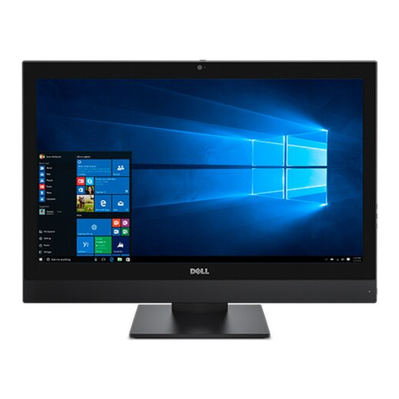
Dell OptiPlex 7440 Owner's Manual
Hide thumbs
Also See for OptiPlex 7440:
- Owner's manual (56 pages) ,
- Setup and specifications (32 pages) ,
- Instructions (4 pages)

Related Manuals for Dell OptiPlex 7440


Summary of Contents for Dell OptiPlex 7440
- Page 1 Dell OptiPlex 7440 All-In-One Owner's Manual Regulatory Model: W11C Regulatory Type: W11C001...
- Page 2 WARNING: A WARNING indicates a potential for property damage, personal injury, or death. Copyright © 2015 Dell Inc. All rights reserved. This product is protected by U.S. and international copyright and intellectual property laws. Dell and the Dell logo are trademarks of Dell Inc.
-
Page 3: Table Of Contents
Contents 1 Working on your computer.................6 ....................6 Before working inside your computer ..........................7 Recommended tools ........................7 Turning off your computer .....................8 After working inside your computer .......................... 8 Important Information 2 Removing and installing components.............. 9 ..........................9 Removing the stand .......................... - Page 4 ......................26 Removing the intrusion switch ......................27 Installing the intrusion switch ..........28 Removing the power and On-Screen Display (OSD) buttons board ..................28 Installing the power and OSD buttons board ......................29 Removing the coin cell battery ......................29 Installing the coin cell battery ........................29 Removing the processor ........................
- Page 5 ..........................55 Drives specifications ..................... 55 Port and connector specifications ........................... 56 Power specifications ......................56 Camera (optional) specifications ..........................56 Stand specifications .........................57 Physical specifications ......................57 Environmental specifications 5 Contacting Dell....................59...
-
Page 6: Working On Your Computer
Damage due to servicing that is not authorized by Dell is not covered by your warranty. Read and follow the safety instructions that came with the product. -
Page 7: Recommended Tools
Disconnect all network cables from the computer. Disconnect your computer and all attached devices from their electrical outlets. Press and hold the power button while the computer is unplugged to ground the system board. Remove the cover. CAUTION: Before touching anything inside your computer, ground yourself by touching an unpainted metal surface, such as the metal at the back of the computer. -
Page 8: After Working Inside Your Computer
Connect your computer and all attached devices to their electrical outlets. Turn on your computer. If required, verify that the computer works correctly by running Dell Diagnostics. Important Information NOTE: Avoid using the touchscreen in dusty, hot, or humid environments. -
Page 9: Removing And Installing Components
Removing and installing components This section provides detailed information on how to remove or install the components from your computer. Removing the stand Follow the procedure in Before Working Inside Your Computer. Place the computer on a flat surface with the display side facing downwards. Perform the following steps as shown in the illustration: a. -
Page 10: Installing The Stand
Installing the stand Align the stand and slide it on the back of the computer. Press the cover attached to the stand, until it snaps in. Follow the procedure in After Working Inside Your Computer. Removing the cable cover Follow the procedures in Before Working Inside Your Computer. -
Page 11: Installing The Cable Cover
Installing the cable cover Align the notches on the cable cover to the holes on the computer and press down, until it snaps in. Tighten the screw to secure the cable cover to the computer. Install the stand. Follow the procedures in After Working Inside Your Computer. -
Page 12: Installing The Back Cover
Installing the back cover Align the notches on the back cover to the holes on the computer and press it until it snaps in. Install the: cable cover stand Follow the procedure in After Working Inside Your Computer. Removing the speaker cover Follow the procedure in Before Working Inside Your Computer. -
Page 13: Installing The Speaker Cover
Slide and remove the speaker cover from the computer. Installing the speaker cover Align the speaker cover to its position on the back of the computer. Tighten the screws to secure the speaker cover to the computer. Install the: back cover cable cover stand Follow the procedure in... -
Page 14: Removing The Hard-Drive Assembly
Removing the hard-drive assembly Follow the procedure in Before Working Inside Your Computer. Remove the: stand back cover Perform the following steps as shown in the illustration: a. Press the tab on the bracket and slide the hard-drive assembly until the tabs are released from either side of the assembly [1]. -
Page 15: Installing The Hard-Drive Assembly
Installing the hard-drive assembly Align the hard drive until the notches are aligned and the hard drive is secured in the bracket. Place the hard drive on the hard-drive cage, until the notches are aligned and it snaps in. Install: back cover stand Follow the procedure in... -
Page 16: Installing The Optical-Drive Assembly
Installing the optical-drive assembly Tighten the screws to secure the bracket to the optical drive. Insert the optical-drive assembly into the drive slot, until it snaps in. Install the: back cover stand Follow the procedure in After Working Inside Your Computer. -
Page 17: Installing The System-Board Shield
Installing the system-board shield Align and slide the system-board shield until it snaps in. Install the: back cover stand Follow the procedure in After Working Inside Your Computer. Removing the heat sink Follow the procedure in Before Working Inside Your Computer. -
Page 18: Installing The Heat Sink
Installing the heat sink Align and place the heat sink in the slot. Tighten the screws to secure the heat sink to the computer. Install the: system-board shield back cover stand Follow the procedure in After Working Inside Your Computer. Removing the WLAN card Follow the procedure in Before Working Inside Your... -
Page 19: Installing The Wlan Card
Installing the WLAN card Align the WLAN card to the connector on the system board. Tighten the screw to secure the WLAN card to the system board. Connect the antenna cables to the connectors on the WLAN card. Install the: system-board shield back cover stand... -
Page 20: Installing The Speakers
Installing the speakers Align the speaker module on the slot in the chassis. Tighten the screws to secure the speaker to the chassis. Thread the speaker cables via the clips. Connect the speaker cable to the connector on the system board. Install: system-board shield speaker cover... -
Page 21: Installing The Converter Board
Perform the following steps as shown in the illustration: a. Remove the screws that secure the converter board to the chassis [1]. b. Lift the converter board away from the chassis [2]. Installing the converter board Place the convertor board in its slot. Tighten the screws to secure the converter board to the chassis. -
Page 22: Removing The Power Supply Unit (Psu)
Removing the Power Supply Unit (PSU) Follow the procedure in Before Working Inside Your Computer. Remove the: stand back cover cable cover speaker cover system-board shield Perform the following steps as shown in the illustration: a. Unthread the power-supply cables from the retention clips in the chassis [1]. b. -
Page 23: Installing The Power Supply Unit (Psu)
Perform the following steps as shown in the illustration: a. Remove the screw that secure the PSU to the chassis [1]. b. Slide the PSU and lift it away from the chassis [2]. Installing the Power Supply Unit (PSU) Place the PSU on the chassis. Tighten the screw to secure the PSU to the chassis. -
Page 24: Removing The Vesa Mount Bracket
Install the: system-board shield speaker cover cable cover back cover stand Follow the procedure in After Working Inside Your Computer. Removing the VESA mount bracket Follow the procedure in Before Working Inside Your Computer. Remove the: stand back cover system-board shield power-supply unit Perform the following steps as shown in the illustration: a. -
Page 25: Removing The Processor Fan
Follow the procedure in After Working Inside Your Computer. Removing the processor fan Follow the procedure in Before Working Inside Your Computer. Remove the: stand back cover system-board shield power-supply unit VESA mount bracket Perform the following steps as shown in the illustration: a. -
Page 26: Removing The Memory Module
Removing the memory module Follow the procedure in Before Working Inside Your Computer. Remove the: stand back cover system-board shield Pry the retention clips away from the memory module until it pops-up. Lift and remove the memory module from its connector. Installing the memory module Align the notch on the memory-card with the tab in the system-board connector. -
Page 27: Installing The Intrusion Switch
Perform the following instructions as shown in the illustration: a. Remove the screw that secures the intrusion switch to the chassis [1]. b. Slide and lift the intrusion switch to remove it from the computer [2]. Installing the intrusion switch Place the intrusion switch in the slot on the computer. -
Page 28: Removing The Power And On-Screen Display (Osd) Buttons Board
Removing the power and On-Screen Display (OSD) buttons board Follow the procedure in Before Working Inside Your Computer. Remove the: stand back cover Perform the following steps as shown in the illustration: a. Remove the screw to remove the metal plate that secures the power and OSD buttons board to the computer [1]. -
Page 29: Removing The Coin Cell Battery
Removing the coin cell battery Follow the procedure in Before Working Inside Your Computer. Remove the: stand back cover system-board shield Press the latch to release the coin cell battery and remove it from the computer. Installing the coin cell battery Insert the coin cell battery into its slot on the system board, until it fits securely. -
Page 30: Installing The Processor
NOTE: After removing the processor, place it in an antistatic container for reuse, return, or temporary storage. Do not touch the bottom of the processor to avoid damage to the processor contacts. Touch only the side edges of the processor. Installing the processor Align the processor with the socket keys. - Page 31 processor fan Perform the following steps as shown in the illustration: a. Disconnect the optical-drive cable and hard-drive cable from the connectors on the system board [1]. b. Disconnect the touch pad cable from the connector on the system board [2]. c.
- Page 32 Perform the following steps as shown in the illustration: a. Press the latches on either side of the connector and pull the LVDS cable to disconnect it from the system board [1,2]. b. Lift the latch and disconnect the cable from the connector [3,4]. Perform the following steps as shown in the illustration.
-
Page 33: System Board Layout
System Board Layout The following image displays the system board layout of the computer. -
Page 34: Installing The System Board
LVDS connector processor socket camera connector WLAN connector coin-cell battery jumper connector jumper connector jumper connector USB 3.0 connector memory connectors ( SODIMM sockets) USB 3.0 connector audio connector speaker connector audio connector DisplayPort connector HDMI-out connector USB 3.0 connector M.2 SSD slot USB 3.0 connector intrusion-switch connector... -
Page 35: Removing The Display Assembly
Removing the display assembly Follow the procedure in Before Working Inside Your Computer. Remove the: stand back cover cable cover speaker cover VESA mount bracket system-board shield WLAN card optical drive hard drive intrusion switch power and OSD buttons board converter board power-supply unit heatsink... -
Page 36: Installing The Display Assembly
b. Remove the screws that secure the base panel to the chassis [2]. c. Lift the display-panel base from the display bezel [3]. Perform the following steps as shown in the illustration: a. Lift the latch and disconnect the cables [1,2]. b. - Page 37 Align all the cables through their retention clips on the display panel. Tighten the screws to secure the latches to the computer. Install the: system board speakers processor fan heatsink power-supply unit converter board power and OSD buttons board intrusion switch hard drive optical drive WLAN card...
-
Page 38: System Setup
Boot Sequence allows you to bypass the System Setup‐defined boot device order and boot directly to a specific device (for example: optical drive or hard drive). During the Power-on Self Test (POST), when the Dell logo appears, you can: •... -
Page 39: System Setup Options
Table 1. Navigation keys Keys Navigation Up arrow Moves to the previous field. Down arrow Moves to the next field. Enter Allows you to select a value in the selected field (if applicable) or follow the link in the field. Spacebar Expands or collapses a drop‐down list, if applicable. -
Page 40: System Configuration Screen Options
Option Description the check-boxes available on the left hand side. You should enable the Legacy Option ROMs to setup the Legacy boot mode. This Legacy boot mode is not allowed when you enable the Secure Boot. The options are: • Boot Sequence - By default, the Windows Boot Manager check box is selected. - Page 41 Option Description PXE, the type of PXE boot (Legacy PXE or UEFI PXE) depends on the current boot mode and type of option ROMs in use. The UEFI Network Stack is required in order to have UEFI PXE functionality fully enabled. •...
-
Page 42: Security Screen Options
Option Description All the options are enabled by default. NOTE: USB keyboard and mouse always work in the BIOS setup irrespective of these settings. Rear USB This field allows you to enable or disable rear USB ports. Configuration • Enable/Disable Rear USB Ports Side USB This field allows you to enable or disable side USB ports. - Page 43 Option Description System Password Allows you to set, change or delete the system password. NOTE: Successful password changes take effect immediately. Default setting: Not set Internal HDD-0 Allows you to set, change or delete the system’s internal hard disk’s password. Password Default setting: Not set NOTE: Successful password changes take effect immediately.
-
Page 44: Secure Boot Screen Options
Option Description • Deactivate • Disable • Activate NOTE: The Activate and Disable options will permanently activate or disable the feature and no further changes will be allowed Default setting: Deactivate Chassis Intrusion This field controls the chassis intrusion feature. The options are: •... -
Page 45: Performance Screen Options
Option Description Expert Key Allows you to manipulate the security key databases only if the system is in Custom Management Mode. The Enable Custom Mode option is disabled by default. The options are: • • • • If you enable the Custom Mode, the relevant options for PK, KEK, db, and dbx appear. -
Page 46: Power Management Screen Options
Option Description Limit CPUID Value Allows you to limit the maximum value of the Standard CPUID Fuction support. Some operation systems will not complete installation when maximum CPUID Function supported is greater than 3. • Enable CPUID Limit - This option is disabled by default. Intel TurboBoost Allows you to enable or disable the Intel TurboBoost mode of the processor. -
Page 47: Post Behavior Screen Options
Option Description NOTE: This feature is only functional when the AC power adapter is connected. If the AC power adapter is removed during Standby, the system setup removes power from all the USB ports to conserve battery power. • Enable USB Wake Support Default setting: The option is disabled. -
Page 48: Virtualization Support Screen Options
Virtualization support screen options Option Description Virtualization Allows you to enable or disable the Intel Virtualization Technology. Enable Intel Virtualization Technology (default). VT for Direct I/O Enables or disables the Virtual Machine Monitor (VMM) from utilizing the additional hardware capabilities provided by Intel® Virtualization technology for direct I/O. Enable VT for Direct I/O - enabled by default. -
Page 49: Cloud Desktop Screen Options
Follow the procedure to recover BIOS from hard drive. Power on the system. While the blue Dell logo is visible, press the F2 key to enter the System Setup. Press the Num Lock key, and verify that the Num Lock light is on. -
Page 50: Updating The Bios
Updating the BIOS It is recommended to update your BIOS (system setup), on replacing the system board or if an update is available. Re-start the computer. Go to dell.com/support. Enter the Service Tag or Express Service Code and click Submit. -
Page 51: System And Setup Password
NOTE: To locate the Service Tag, click Where is my Service Tag? NOTE: If you cannot find your Service Tag, click Detect My Product. Proceed with the instructions on screen. If you are unable to locate or find the Service Tag, click the Product Category of your computer. Choose the Product Type from the list. -
Page 52: Deleting Or Changing An Existing System And/Or Setup Password
The System Security screen appears. In the System Security screen, verify that Password Status is Unlocked. Select System Password , enter your system password, and press Enter or Tab. Use the following guidelines to assign the system password: • A password can have up to 32 characters. •... -
Page 53: Technical Specifications
Technical specifications NOTE: Offerings may vary by region. For more information regarding the configuration of your computer in: • Windows 10, click or tap Start → Settings → System → About. • Windows 8.1 and Windows 8, click or tap Start →... -
Page 54: Video Specifications
Video specifications Feature Specification Video Controller Integrated Intel HD Graphics (Gen 9 iGfx), 2GB GDDR5 for dGPU (Integrated) Video Memory shared memory External display Display port, HDMI in and HDMI out support Audio specifications Feature Specification Controller Intel High Definition Audio with Waves MaxxVoice Pro Speaker single 4-ohms speakers in both the left and right speaker assembly (4 W average per channel) -
Page 55: Cards Specifications
Cards specifications Feature Specification M.2 slots • One 2230 D3 Key-A M.2 Socket 1 • One 2280 D3 Key-M M.2 Socket 3 Display specifications Feature Specification Type 23.8 inch, FHD and UHD (4K) Maximum 3840 x 2160 resolution Refresh rate 60 Hz Brightness Brightness up/down buttons... -
Page 56: Power Specifications
Feature Specification USB 3.0 (Front/ 2(side)/4 Rear) USB port with 1(side) USB 3.0 PowerShare support Video one display port HDMI • one 19–pin output port • one 19–pin input port Media card reader one 4-in-1 slot Power specifications Feature Specification 155 Watt PSU for 200 Watt dGPU and UHD(4K) -
Page 57: Physical Specifications
Physical specifications Feature Specification Width 575.24 mm (22.65 inches) Height 392.90 mm (15.47 inches) Depth: Non-touch 62.79 mm (2.47 inches) Touch 62.79 mm (2.47 inches) Weight: Non-touch 9.76 kg with stand (21.52 lb) Touch 11.00 kg with stand (24.25 lb) NOTE: The weight of your computer may vary depending on the configuration ordered and the manufacturing variability. -
Page 58: Specifications
Altitude Specifications (maximum) Non-operating 0 m to 5000 m (0 ft to 16,404 ft) Airborne G2 or lower as defined by ANSI/ISA-S71.04-1985 contaminant level... -
Page 59: Contacting Dell
Dell product catalog. Dell provides several online and telephone-based support and service options. Availability varies by country and product, and some services may not be available in your area. To contact Dell for sales, technical support, or customer service issues: Go to Dell.com/support.
Need help?
Do you have a question about the OptiPlex 7440 and is the answer not in the manual?
Questions and answers