
Subscribe to Our Youtube Channel
Related Manuals for Fei Bao Velox XL


Summary of Contents for Fei Bao Velox XL
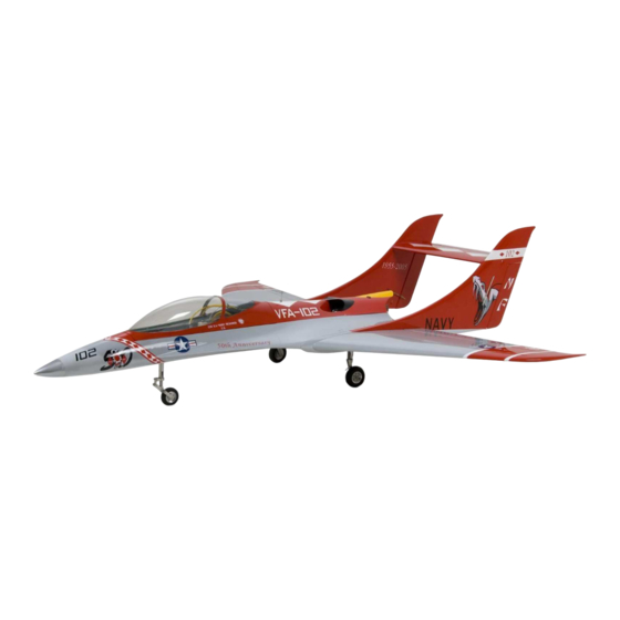
- Page 1 F E I B A O V E L O X FEI BAO JETS Velox XL Assembly Manual Written by Curtis Mattikow In collaboration with R/C Jet Models...
-
Page 2: Before You Begin
F E I B A O V E L O X DISCLAIMER: THIS IS NOT A TOY. This is a high-performance miniature aircraft, capable of high speeds and damage to life, limb, and property. The manufacturer and its distributors cannot control how you assemble this model, what equipment you use to fit it out, or how you fly it, and can assume no liability whatsoever for any damages that may occur when you fly your aircraft. - Page 3 Velox. C. WORKING WITH PNEUMATIC SYSTEMS: The Velox XL uses pneumatic brakes and retracts. If you follow a few tips, you should have very reliable, leak-free operation. Neatness counts. All airlines should be secured to the airframe to keep them from flopping around or getting kinked. Use tie wraps for this.
- Page 4 F E I B A O V E L O X Either one works, just ensure that all ends of all airlines are cut off dead square. Make sure all airlines are pushed ALL THE WAY onto their nipples. They should not need to be secured otherwise, but you can add fine wire safety wraps if you like. Make sure all left and right matching airlines are the same length, particularly the brake lines, or you will get uneven retraction or braking action.
- Page 5 F E I B A O V E L O X 1. Using a sharp knife, trim off the ends of the white nose 4. Cut the tie-wrap holding the nose gear in place for gear steering tubes, to clear the radio tray so you can transportation.
- Page 6 F E I B A O V E L O X 7. Cut off these tubes, leaving about six inches of slack in 11. Make up an airline harness consisting of two four inch the radio compartment, and add a y connector to each. pieces of tubing, a y connector, and another length Tape them to the floor out of the way.
- Page 7 F E I B A O V E L O X 15. Connect the two lower nipples on the door cylinders 19. Slip the retracts into place and secure with screws. with this new harness. Be sure to not pinch the airlines. Figure 15 Figure 19 16.
- Page 8 F E I B A O V E L O X 23. Open the struts with the doors attached (mains) 27. Bundle the lines in the wheel wells together for neatness using tie wraps. Figure 23 Figure 27 24. Add two 16-inch lengths of airline to the brakes and secure to the struts as shown.
- Page 9 F E I B A O V E L O X 31. Glue the air bottles into the fuselage using silicone or 35. Assemble the stoppers as shown. epoxy. Figure 35 Figure 31 36. Add the clunks and lines, secure each end with a tie 32.
- Page 10 F E I B A O V E L O X 39. Install the two saddle tanks. You will need to turn and 43. Insert the main tank and fix it in place. rotate them to get them through the center opening in the main former.
- Page 11 F E I B A O V E L O X 47. Add a pair of servo mounts to one servo, and a link to 51. Coat the bottom of each horn with hysol. Make sure one horn. This will be a dummy rig to establish the the holes are filled with glue.
- Page 12 F E I B A O V E L O X 55. When the hysol is dry, you can paint the horns and 59. Use this harness to connect the vents of the outer fillets to match your airframe for better appearance. tanks, and then tape the overflow line out of the way forward.
- Page 13 F E I B A O V E L O X 63. Use velcro to install the valve on the fuselage floor. 67. Use that section of line and a y connector to connect Check clearance with the radio tray and other the inputs of both the brake and sequencing valves.
- Page 14 F E I B A O V E L O X 71. Attach a wheel collar to a 36-inch piece of string. 75. Gently pull the extension through using the string. Figure 71 Figure 75 72. Tie the loose end of the string to a 36 inch heavy duty 76.
- Page 15 F E I B A O V E L O X 79. Repeat the process for the other boom. Note that the 83. Through the hole in the former behind the main gear extensions must emerge on the inboard side of both as shown.
- Page 16 V E L O X 91. Label the servo lead with the appropriate number. 87. Center the servo and add the horn. Be sure to size the holes in the horn for the provided Fei Bao clevises. Figure 91 Figure 87 92.
- Page 17 F E I B A O V E L O X 95. Screw the servo cover into place. 99. Connect the clevis at the other end, and secure it with the provided safety clip. Figure 95 Figure 99 96. Find the control linkage closest in length and measure it against the needed distance between the centered 100.
- Page 18 F E I B A O V E L O X 107. Test fit your engine to the mounts. Get it as far forward as possible for balance, modify the mounts if 103. Install your UAT to the tray using tie wraps as needed.
- Page 19 F E I B A O V E L O X 111. Slit some airline tubing and CA it around the edges of the hole to give it a smooth edge. 115. Drill pilot holes for the engine mounting screws. Be sure not to drill too far and come out the bottom of the fuselage.
- Page 20 F E I B A O V E L O X Figure 118 123. Plumb and wire the equipment according to your engine manual. Note you may need lines long 119. Plan how you want to install your ECU, solenoids, enough to reach the engine in the rear of the model.
- Page 21 F E I B A O V E L O X 127. Test fit the engine cover and mark it if need be to 131. Crimp the ends of the steering cables to the clear the glow plug. outer holes on the steering tiller on the nose gear. Figure 127 Figure 131 128.
- Page 22 F E I B A O V E L O X 135. Slide the boom all the way into place and stick the flap and aileron connectors through to the outside. 139. Those bolts secure the stab. Figure 135 Figure 139 140.
- Page 23 F E I B A O V E L O X Velox. See the Pilots Notes for balance and control throws. Technical data: Weight with the super bee and two 1800max RC NiCads and full UAT is 28.5 Lbs. CG is 7 ¼” back from the wing root (not the boom root) it’s nice and safety for the first flight.
- Page 24 F E I B A O V E L O X You may want an up-elevator mix with flap application, as the nose pitches down. You may also want some additional up-elevator throw available with full flaps, as you may not have enough elevator to flare with full flaps. A "landing"...
Need help?
Do you have a question about the Velox XL and is the answer not in the manual?
Questions and answers