Advertisement
Quick Links
Fei Bao Jets
May 2012
Mirage F1 Assembly Manual
Written by Dawid Visser
Congratulations on your purchase of the Fei Bao Mirage F1 Jet.
May you enjoy this model jet aircraft and we wish you many happy landings.
Disclaimer:
THIS IS NOT A TOY. This is a high performance miniature
aircraft, capable of high speeds and capable to cause injury
of even death or damage to property. The manufacturer and its
distributors cannot control how you assemble, what equipment
you use to fit it out, or how you operate and fly it and
This page was created using BCL ALLPDF Converter trial software.
To purchase, go to
http://store.bcltechnologies.com/productcart/pc/instPrd.asp?idproduct=1
Advertisement

Related Manuals for Fei Bao Mirage F1


Summary of Contents for Fei Bao Mirage F1
- Page 1 May 2012 Mirage F1 Assembly Manual Written by Dawid Visser Congratulations on your purchase of the Fei Bao Mirage F1 Jet. May you enjoy this model jet aircraft and we wish you many happy landings. Disclaimer: THIS IS NOT A TOY. This is a high performance miniature aircraft, capable of high speeds and capable to cause injury of even death or damage to property.
- Page 2 cannot assume any liability for any damages, injury or death that may occur when you operate or fly this aircraft. By assembling this model you agree to indemnify and hold blameless the manufacturer and his/ her agents from any and all sorts of liability associated with the use of this product.
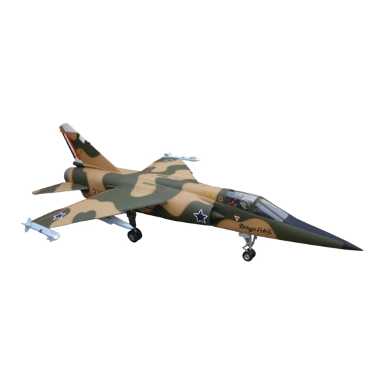
- Page 3 Wingspan:1.37m Weight:13.5kg The Aircraft: The Dassault Mirage F1 is a French built single seat air superiority fighter and attack aircraft designed and built by Dassault Aviation as a successor to the Mirage III family. Maiden flight was on 23 December 1966 and the aircraft entered service in the early 1970’s.
- Page 4 Radio: Futaba 10C with R6014HS receiver Servos: 2x JR DS 8711 for elevators, 2x Hitec HS 5245 MG for ailerons, 2x Hitec HS 7985 MG for flaps, 1x Diamond D 300 for steering, JR DS 171 for rudder. Electics: Power Box evolution with 2x 7.4v 2100mah Lipo batteries.
- Page 5 screws at the retract units and check that the lower part twists at the shock strut (as per the real aircraft). If not it is probably dirty with paint inside and you will need to take it apart, clean it out and give it some light grease for lubrication.
- Page 6 Wings. Epoxy(or use Hysol glue) the control horns into the control surfaces. Also do the hinges (Apply Vaseline to the pivot points to keep the epoxy or Hysol out). Trial fit them and check adequate amount of movement available and epoxy in place. Fit the servos using the brackets and screws supplied for the flap servos.
- Page 7 before attaching the fin to the rear fuselage.Secure the fin rear shaft in the fitting and tighten the hex screw. The forward attachment shaft also slides into its fitting and is then secured from the inside of the fuselage with the screw and washer that you tested.
- Page 8 Channel 1: Ailerons via Power Box 1. Channel 2: Left Elevator via Power Box 2. Channel 3: Throttle via receiver to ECU. Channel 4: Rudder and Nosewheel steering via rx. ch. 4. Channel 5: Gear via receiver to sequencer. Channel 6: Flaps via Power Box 5 (Use programmer to synchronise the flaps.
- Page 9 Flying. Despite the small wings the Mirage F1 handles quite well at low speed. For take off make sure you have enough speed and gently feed in increasing elevator to let her fly off when she wants to. The ailerons are quite powerful despite their small size so take care not to be too active on them.
- Page 10 Nosewheel steering arm where I filed flat spots. Point for another flat spot at the scissor link at bottom of nose gear. Flat spot position for nosewheel steering arm. This page was created using BCL ALLPDF Converter trial software. To purchase, go to http://store.bcltechnologies.com/productcart/pc/instPrd.asp?idproduct=1...
- Page 11 Nosewheel retract disassembled. Left main gear leg. Right main gear leg. This page was created using BCL ALLPDF Converter trial software. To purchase, go to http://store.bcltechnologies.com/productcart/pc/instPrd.asp?idproduct=1...
- Page 12 Both main gear legs. Left main gear pivot mechanism. Right main gear pivot mechanism. This page was created using BCL ALLPDF Converter trial software. To purchase, go to http://store.bcltechnologies.com/productcart/pc/instPrd.asp?idproduct=1...
- Page 13 Main gear retract unit disassembled. Main wheel brake detail. Main gear pivot system. This page was created using BCL ALLPDF Converter trial software. To purchase, go to http://store.bcltechnologies.com/productcart/pc/instPrd.asp?idproduct=1...
- Page 14 Hinges installed on control surfaces. Rudder pushrod detail. Fin forward rod attachment. This page was created using BCL ALLPDF Converter trial software. To purchase, go to http://store.bcltechnologies.com/productcart/pc/instPrd.asp?idproduct=1...
- Page 15 Fin attachment detail. Bracket for direct nose wheel steering servo. Another view of direct nose wheel steering. This page was created using BCL ALLPDF Converter trial software. To purchase, go to http://store.bcltechnologies.com/productcart/pc/instPrd.asp?idproduct=1...
- Page 16 Fuel tank assembly. On the right is plywood shelf for filling lines. This page was created using BCL ALLPDF Converter trial software. To purchase, go to http://store.bcltechnologies.com/productcart/pc/instPrd.asp?idproduct=1...
- Page 17 Detail of shelf fitting bracket. Notch where shelf slides in. View into nose section showing brake air bottle for brakes and Jet Tronic valves. This page was created using BCL ALLPDF Converter trial software. To purchase, go to http://store.bcltechnologies.com/productcart/pc/instPrd.asp?idproduct=1...
- Page 18 View into nose section from the rear showing the shelf where the Power Box (towards front) and the Turbine ECU (towards the rear) will be installed. Optional positions are above the landing gear bearer or the space behind the engine intake ducts. Power Box on its tray slid out into the cockpit.
- Page 19 The nose section and main fuselage before joining. Fuselage and nose section before joining. Note all the air lines (Looks like spaghetti!!) Dowel rod and hex key to ease the joining of nose section and fuselage. It was wrapped with isolation tape and was strong enough for the task.
- Page 20 Aileron pushrod. Aileron pushrod. Flap pushrod. This page was created using BCL ALLPDF Converter trial software. To purchase, go to http://store.bcltechnologies.com/productcart/pc/instPrd.asp?idproduct=1...
- Page 21 Flap pushrod. Flap and aileron pushrods. CG calculation. This page was created using BCL ALLPDF Converter trial software. To purchase, go to http://store.bcltechnologies.com/productcart/pc/instPrd.asp?idproduct=1...
- Page 22 Wing underside with missiles attached. Elevator pushrod connection. Elevator control detail. This page was created using BCL ALLPDF Converter trial software. To purchase, go to http://store.bcltechnologies.com/productcart/pc/instPrd.asp?idproduct=1...
- Page 23 Fin installation bolt and fitting. Equipment arrangement in front cockpit area. Eguipment in cockpit. This page was created using BCL ALLPDF Converter trial software. To purchase, go to http://store.bcltechnologies.com/productcart/pc/instPrd.asp?idproduct=1...
- Page 24 Cockpit rear view. Cockpit details with pilot. Instrument panel. This page was created using BCL ALLPDF Converter trial software. To purchase, go to http://store.bcltechnologies.com/productcart/pc/instPrd.asp?idproduct=1...
- Page 25 Fuel tank viewed from cockpit. Engine bay from left. Engine bay from right. This page was created using BCL ALLPDF Converter trial software. To purchase, go to http://store.bcltechnologies.com/productcart/pc/instPrd.asp?idproduct=1...
- Page 26 Pipe and exhaust. Rear of engine. Below engine. Note lower pipe support. This page was created using BCL ALLPDF Converter trial software. To purchase, go to http://store.bcltechnologies.com/productcart/pc/instPrd.asp?idproduct=1...
- Page 27 Right landing gear wheel well area. Right landing gear details. Right wheel bay and ECU switch under the air brake. This page was created using BCL ALLPDF Converter trial software. To purchase, go to http://store.bcltechnologies.com/productcart/pc/instPrd.asp?idproduct=1...
- Page 28 Rear right view. Tailpipe rear view. Rear view into rear fuselage. This page was created using BCL ALLPDF Converter trial software. To purchase, go to http://store.bcltechnologies.com/productcart/pc/instPrd.asp?idproduct=1...
- Page 29 Right front view. Left front view. Final preparations for maiden flight. This page was created using BCL ALLPDF Converter trial software. To purchase, go to http://store.bcltechnologies.com/productcart/pc/instPrd.asp?idproduct=1...
- Page 30 Engine start for maiden flight. Airborne on maiden flight. Shortly after take-off flying beautifully. This page was created using BCL ALLPDF Converter trial software. To purchase, go to http://store.bcltechnologies.com/productcart/pc/instPrd.asp?idproduct=1...
- Page 31 2. My family who support our hobby. 3. Mike Starke, a fellow jet modeller for all your advice and sharing your knowledge. 4. Chris Pretorius, a pilot of the real Mirage F1 for advice and support. 5. Colin Strauss who shared information also by means of articles of the aircraft in “Radio Controlled Jet...
Need help?
Do you have a question about the Mirage F1 and is the answer not in the manual?
Questions and answers