Advertisement
Quick Links
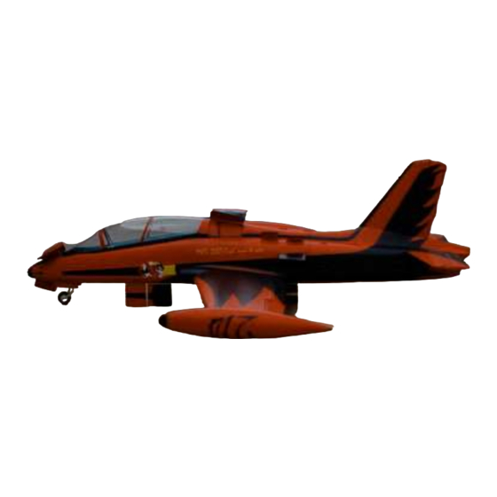
Fei Bao MB–339 Instructions
DISCLAIMER
THIS IS NOT A TOY. This is a high-performance miniature aircraft,
capable of high speeds and damage to life, limb, and property. The
manufacturer and its distributors cannot control how you assemble
this model, what equipment you use to fit it out, or how you fly it,
and can assume no liability whatsoever for any damages that may
occur when you fly your aircraft. By assembling this model, you are
agreeing to indemnify and hold blameless the manufacturer and/or
his agents from any and all torts and liability associated with the use
of this product. Please inspect all parts before beginning assembly.
If any parts appear to be suspect, contact your dealer or the
manufacturer for repair or replacement BEFORE you begin. Once
you have assembled the aircraft, you are the pilot in command and
assume any and all responsibility for the use of the model and any
damages that might occur by flying or attempting to fly this aircraft.
R/C model jets require a high level of skill in both their assembly and
their flying. If you do not feel confident in either your building or
flying skills, PLEASE seek assistance from more experienced
modelers. It is a wise idea, no matter what level of skills you
possess, to have a second experienced modeler go over your
installation after assembly. A second set of eyes may spot a problem
you have missed. If you have not flown a model like this before, it is
HIGHLY recommended that you get an experienced turbine pilot to
do your maiden flight. Very often, the first few seconds of a maiden
flight are critical until the aircraft is trimmed out, and having an
experienced pilot at the controls can make the difference between a
wrecked aircraft and once that enjoys many hundreds of flights. Be
sure to select a suitable field for flying...take the time to find a large
paved runway if at all possible, especially for test flights, until you
feel comfortable getting the aircraft in and out of smaller grass
fields.
Before you begin
Keep this in mind as you proceed:
Look at EVERY assembly step you finish, and ask yourself:
"Is this going to crash my airplane?"
A chain is only as strong as its weakest link, and this is a high-
performance aircraft that will be very intolerant of sloppy assembly
techniques. Even the smallest component is important and can
cause the loss of your airplane, so take the time to do things right.
Or REdo them if they are wrong. Careful work will result in a long-
lasting plane that gives you years of pleasure, one loose component
could result in the complete loss of the aircraft and all the
components inside it, and someone can even get hurt. So pause
every once in a while when building it and double-check your
workmanship.
Introduction
You have chosen a model that represents the pinnacle of ARF
technology. While there is not a lot of building to do, there is
enough to keep you busy for a few evenings.
Even if you have assembled maybe other ARF jets, we highly
recommend following our assembly sequence and procedures
anyway. Chances are it will save you a lot of time, prevent you from
running down dead ends, and perhaps remind you of a few small
things that might end up saving your aircraft.
We have tried to arrange a construction sequence that will allow you
to keep moving forward, rather than standing around waiting for
glue to dry before you can proceed to the next step.
Just because the model is almost completely built does not mean
you can rush through the final assembly.
You need to employ fine craftsmanship every step of the way,
1
Advertisement

Related Manuals for Fei Bao MB-339


Summary of Contents for Fei Bao MB-339
- Page 1 Fei Bao MB–339 Instructions wrecked aircraft and once that enjoys many hundreds of flights. Be sure to select a suitable field for flying...take the time to find a large...
- Page 2 turbine models are critical. Keep this in mind with everything you (they are approximately $10), or you can make up a little jig to hold do, every part you install...look at the work you just did, evaluate it the airline and keep a sharp, new razor blade perfectly upright as critically, and ask yourself "is this going to potentially crash my you cut.
-
Page 3: Preliminary Steps
Other Parts • Construction BVM UAT (optional) • Fuel tank vent fitting • Festo fuel shutoff valve • Wire twist tie (optional) • Blue Loctite • Glues: Thin CA, 5 minute epoxy, 30 minute epoxy, • Aeropoxy, Zap-a-Dap-a-Goo Electronic gear sequencer, or UP2/UP4 combination •... - Page 4 Step 1: Check Forward Fuselage Step 2: Prepping the Fuel System Remove the fuel tanks from the fuselage. photo 2 Disassemble and inspect the tank cap hardware. As shows, Also remove the two forward component boards. Now would be the process used to cut the tubes may leave behind a rim that a good time to put a coat of paint on these parts if you would constricts fuel flow and could result in excess tank pressure and like to protect the wood surfaces.
- Page 5 You should also notch the vent tube with a small file to provide tanks while fitting the Tygon. Slowly wiggle the tubing into for continued air flow should the tube come into contact with the place. Wire tie for security. top of the tank.
- Page 6 Position the center tank on top of the intakes, far enough aft of Check the position of the tank once more with the engine hatch the canopy area to allow clearance for the fuel lines. in place. When satisfied, tack glue the tank support in place photo 5 Fashion a rear tank support from ¼”...
- Page 7 Connect this “T” fitting to the vent line of the center tank. Attach this “T” fitting to a fuselage vent fitting. It is suggested Connect the two vent lines together from the saddle tanks with a you place this just ahead of the right intake, slightly up from the “T”...
- Page 8 Connect the fuel pickup from the center tank to the optional UAT Step 5: Nose Doors or to the fuel pump. In the prototype, the UAT is located just photo 11 It will be helpful at this point to locate the positioning of the air above the right intake.
- Page 9 In the prototype, the larger of the three air tanks serves the gear As described in the general notes, the twin doors that flank the and doors, while the smaller tanks serve brakes and air brake nose gear strut in the prototype are activated by an air micro respectively.
- Page 10 tape wrapped around the cutter at the proper depth will help Step 7: Horizontal Stabilizers prevent a mishap. The horizontal stabs build up in a similar fashion to the vertical Roughen the surface of the control arm where it will glue into stab.
- Page 11 proper diameter was achieved with a conical bit and then the Push the spars fully into the stab that you just mounted, and photo 18 depth was cut with a small carbide cutter ( then slip the other stab on the spars, securing with a bolt. Slip one horizontal stab on the spars and secure with a bolt Loctite.
- Page 12 Move the pipe aft and position the lower bypass on the Step 9: Aft Fuselage mounting rails. Trim the engine rails as necessary for a good fit. Drill a hole in the pipe mounting tabs at their mid-point. Bolt the pipe mounting tabs to the lower bypass. Position the pipe on the rear of the lower bypass.
- Page 13 photo 23 – engine mounted in lower bypass photos 24 and 25 – rear component board. Note receiver position on upper right. Shim the engine as necessary to make sure it is centered in the pipe and is aligned with the slope of the pipe from front to rear. Drill and secure the bypass to the engine mounting rails with When you are satisfied, bolt the engine to the side frames with four wood screws if necessary.
- Page 14 photo 26 – enlarge air line and servo wire access hole in wing root photo 27 – optional repositioning of main door cylinder attach bolt Extend main gear, remove the small screw that attaches the Attach air lines to the door cylinder if not already accomplished. strut cover linkage to the strut, and remove the main gear.
- Page 15 photo 28 – completed main gear and door installation photo 29 – flap servo installation Step 11: Aileron and Flap Servos You will need to use an extension on the aileron servo lead. Make sure to tape the connection and secure the wiring to ribs Remove the aileron and flap servo covers.
- Page 16 Set the wings aside for the glue to cure. Double check to make sure there are no fingerprints or excess glue on the wing surfaces. When the glue has cured, install the linkages. Insert the wing tip tanks into the mounting holes. When the pins are fully inserted, tighten the locking clamp bolts through the small holes in the bottom of the wing.
- Page 17 Carefully fit the front tub into place, trimming as necessary. photo 33 Glue into place with Zap-a-Dap-a-Goo ( ). Recheck the fit of the canopy into the forward fuse before the glue fully dries. photo 31- use the cockpit as a template to trim the back of the aft tub to shape Attach the rear instrument panel to the tub in the same fashion photo 32 photo 33 –...
-
Page 18: Equipment Installation Photos
Step 16: Weight and Balance Test fuel the aircraft. Check for leaks, then drain. Set your CG. For the initial flights, the plane should balance slightly nose down with the CG on the wing spar, fuel in the UAT only, with the gear down. Adjust CG as necessary. -
Page 19: Parts List
Parts List Forward Fuselage and Component Boards • Aft Fuselage • Engine Hatch • Canopy • Horizontal Stabs, Elevators (2) • Carbon Fiber Spars for Horizontal Stabs (2) • Vertical Fin, Rudder • Wings, Flaps, Ailerons (2) • Wing Tip Tanks (2) •...
Need help?
Do you have a question about the MB-339 and is the answer not in the manual?
Questions and answers