Table of Contents
Advertisement
R -
NOTE: Read the entire instruction manual before starting the installation.
Please read this Owner's Information Manual carefully before installing and using this appliance
and keep this manual for future reference.
For your convenience, please record the model and serial numbers of your new equipment in the
spaces provided. This information, along with the installation data and dealer contact information
will be helpful should your system require maintenance or service.
UNIT INFORMATION
Model #
Serial #
INSTALLATION INFORMATION
Date Installed
421 02 9240 00
OWNERS MANUAL
-
- 410A Ductless Split System
High-Wall Heat Pump
MODELS:DLFBB - Indoor
SIZES: 09, 12, 18, 24K
NOTE TO EQUIPMENT OWNER:
Specifications are subject to change without notice.
TABLE OF CONTENTS
SAFETY CONSIDERATIONS . . . . . . . . . . . . . . . . . . . . . . . . . 2
SYSTEM REQUIREMENTS . . . . . . . . . . . . . . . . . . . . . . . . . . 2
. . . . . .
. . . . . . . . . . . . . . . . . . . . . . . . . . . . . . . . . . . . . . . . . . . 5
CLEARANCES. . . . . . . . . . . . . . . . . . . . .
SELECTION OF INSTALLATION LOCATION . . . . . . . . . . . . . 18
DEALERSHIP CONTACT INFORMATION
Company Name:
Address:
Phone Number:
Technician Name:
. . . . . . . . . . . . . . . . . . . . . . . . . . . . . . . . . . . . 3
. . . . . . . . . . . . . . . . . . . . . . . . . 4
. . . . . . . . . . . . . . . . . . . . . . . . . . . . . 10
. . . . . . . . . . . . . . . . . . . . . . . . 11
. . . .
. . . .
. . . . . . . . . . . . . . . . . . . 13
. . .
. . .
. . . . . . . . . . . . . . . . . . . . . . . . . . 18
. .
. .
. . . .
. .
. .
. . . .
. .
. . . .
. .
. . . . . .
. .
PAGE
. . . . . . . . . . . . 17
. . . . . . . . . . . . . 19
. . . . . .
. . . . . . . 20
. . . . . .
. . . . . . . 25
. . . . . .
. . . . . . . 26
. . . . . .
. . . . . . . 28
Advertisement
Table of Contents

Related Manuals for International comfort products DLFBB09K


Summary of Contents for International comfort products DLFBB09K
-
Page 1: Table Of Contents
OWNERS MANUAL - 410A Ductless Split System High-Wall Heat Pump MODELS:DLFBB - Indoor SIZES: 09, 12, 18, 24K NOTE: Read the entire instruction manual before starting the installation. TABLE OF CONTENTS PAGE SAFETY CONSIDERATIONS ......2 SYSTEM REQUIREMENTS . -
Page 2: Safety Considerations
CAUTION SAFETY CONSIDERATIONS Installing, starting up, and servicing air- -conditioning equipment can be hazardous due to system pressures, electrical components, EQUIPMENT DAMAGE HAZARD and equipment location (roofs, elevated structures, etc.). Failure to follow this caution may result in equipment Only trained, qualified installers and service mechanics should damage or improper operation. -
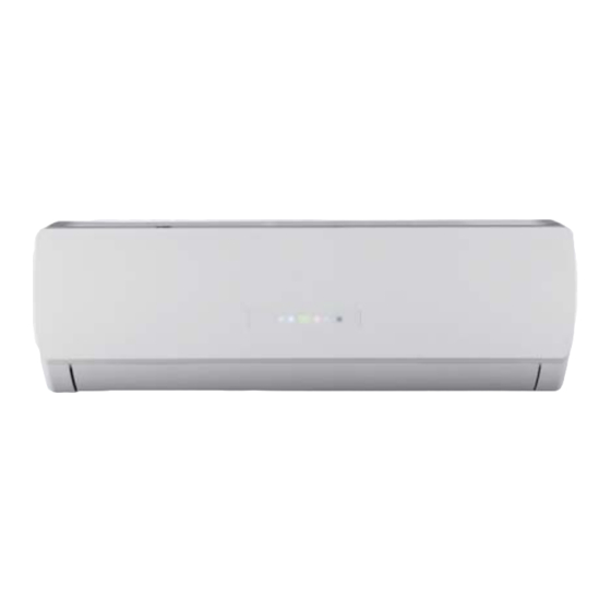
Page 3: Parts Name
Parts Name Indoor Unit air inlet panel filter aux.button horizontal louver air outlet cooling power receiver indicator indicator window display heating temp. drying indicator indicator indicator remote controller Notice: Actual product may be different from above graphics, refer to actual products. Working temperature range Operating Temperature Range(Optional) Indoor side DB/WB(... -
Page 4: Model Number Reference
Position 11 - Not Defined Position 10 – Not Defined Position 9 - Electrical characteristics J = 115/l/60 K = 208-230/l/60 H = 208-230/3/60 L = 460/3/60 Position 7, 8 - System capacity in 1000 BTU/Hr Example: 09 = 9000 BTU/Hr Position 6 - Indoor Fan Coil Unit Type B = High-Wall C = Cassette... -
Page 5: How To Use The Remote Control To Operate The Unit
How to use the remote control to operate the unit OPERATION INSTRUCTIONS Remote Controller Description ON/OFF Press to start or stop operation. : Press to decrease temperature setting. : Press to increase temperature setting. MODE Press to select the operation mode (AUTO/COOL/DRY/FAN/HEAT). - Page 6 How to use the remote control to operate the unit OPERATION INSTRUCTIONS Remote Controller Description ON/OFF : Press this button to turn on the unit .Press this button again to turn off the unit. Press this button to decrease the set temperature. Hold it down for more than 2 seconds to rapidly decrease the set temperature.
- Page 7 How to use the remote control to operate the unit OPERATION INSTRUCTIONS ress this button to activate the on and off healthy and scavenging functions in the operation status. Press this button one time to start the scavenging function; the LCD displays the“ ”icon.
- Page 8 How to use the remote control to operate the unit OPERATION INSTRUCTIONS QUIET: Press this button, the Quiet status is under the Auto Quiet mode (display " " and "Auto" signal) along with the Quiet (display " " signal and the Quiet OFF modes (the signal " "...
- Page 9 How to use the remote control to operate the unit OPERATION INSTRUCTIONS Combination of "the MODE " and "-" buttons: Switches between Fahrenheit and centigrade " " - " " In the OFF mode, press the MODE buttons simultaneously to switch between Combination of "...
-
Page 10: Emergency Operation
Emergency operation If the remote controller is lost or damaged, use the auxiliary button to turn on or turn off the air conditioner. The operation details are as below. open the air conditioner. When the air conditioner is turned on, it operates under the auto mode. -
Page 11: Clean And Maintenance
Clean and Maintenance Open panel Pull out the panel to a certain ℉ panel cover tightl . Note: an abundance of operation environment, clean frequenc 421 02 9240 00 Specifications are subject to change without notice... -
Page 12: Clean And Maintenance
Clean and Maintenance Checking before use season 1. Check whether the air inlets and air outlets are blocked. 2. Check whether the circuit breaker, is in good condition. Check whether the filter is clean. 4. Check whether the drainage pipe is damaged. Checking after use season 1. -
Page 13: Malfunction Analysis
Malfunction analysis General phenomenon analysis Check below items before asking for maintenance. If the malfunction still Phenomenon Check items Solution within the signal receiving range? 26.25 FT (8M). Select proper angle and point pointing at the receiving the remote controller at the re- Indoor unit window? ceiving window on the indoor unit. -
Page 14: Malfunction Analysis
Malfunction analysis Phenomenon Check items Solution Breaker burnt out? Breaker or fuse. Air condit- Wiring is damaged ioner can not operate after stopping operation? on the unit again. for remote controller is correct? Mist is em- rapidly. After a while, the indoor itted from temperature and humidity will indoor unit’s... -
Page 15: Malfunction Analysis
Malfunction analysis Phenomenon Check items Solution there is a an odor Odors are source,such as furniture and emitted cigarette. The noise is the sound of “ ater Air conditioner is turned on or turned off recently? the unit, which is normal . noise This is the sound of friction Air conditioner is turned on or... - Page 16 Malfunction analysis Error Code Refer to the list below for and is Indoor ambient temperature sensor malfunction Indoor tube temperature sensor malfunction Jumper connection malfunction protection Indoor unit fan motor does not operate properly Communication error between indoor and outdoor unit there are Warning one of the following issues...
-
Page 17: Clearances
CLEARANCES CEILING 6" (0.15m) min. 5" 5" (0.13m) (0.13m) min. min. (1.8m) FLOOR Fig. 5 – Indoor Unit Clearance CLEARANCES - OUTDOOR Air-inlet Air-outlet Fig. 6 – Clearances Outdoor UNIT Minimum Value in. (mm) 24 (609) 24 (609) 24 (609) 4 (101) 4 (101) 421 02 9240 00... -
Page 18: Tools For Installation
Tools for installation Level meter Screw driver Impact drill Drill head Pipe expander Torque wrench Open-end wrench Pipe cutter Leakage detector Vacuum pump Pressure meter Universal meter Inner hexagon spanner Measuring tape Note: Selection of installation location Indoor unit Basic requirement Installing the unit in the following pla- 1. -
Page 19: Requirements For Electric Connection
Requirements for electric connection Safety precaution 1. Must follow the electric safety regulations when installing the unit. Breaker . 3. Make sure the power supply matches the air conditioner's requirements. Unstable power supply or incorrect wiring may cause a malfunction. Install proper power supply cables before using the air conditioner. -
Page 20: Installation Of Indoor Unit
Installation of indoor unit Step one: choosing the installation location Step two: install wall-mounting frame 1. Hang the wall-mounting frame on the wall; adjust it in horizontal position with the place anchors anchors in the holes. 3. Secure the wall-mounting frame on the wall with tapping screws and anchors are Step three: open piping hole 1. - Page 21 Installation of indoor unit Indoor outdoor Note: opening the hole. 2 1/6 in (55mm)/ 2 3/4 in (70mm) The plastic expansion particles are 5-10 purch- ased locally. Step four: outlet pipe 1. The pipe can be led out in the 2.
-
Page 22: Installation Of The Indoor Unit
Installation of the indoor unit open-end Hex nut diameter Tightening torque[ft.lb(N.m)] wrench 1/4 in (6 mm) 20.34~27.12 ft.lb(15~20 N.m) 40.68~54.24 ft.lb(30~40 N.m) 3/8 in (9.52 mm) union nut 54.24~74.58 ft.lb(40~55 N.m) 1/2 in (12 mm) pipe torque wrench 5/8 in (16 mm) 81.36~88.14 ft.lb(60~65 N.m) 3/4 in (19 mm) 94.93~101.7 ft.lb(70~75 N.m) - Page 23 Installation of indoor unit 2. Pull the power wiring from the back of the unit to the front side using the wire channel. cable-cross hole power connection 3. Remove the wire clip; connect the power wire connection wire to the wiring terminal according to the color;...
- Page 24 Installation of indoor unit Step eight: bind up pipe drain hose 1. Bind up the connection pipe, power connection pipe band wire and drain hose with the band. indoor unit indoor and outdoor power cord pipe indoor power wire liquid pipe 3.
-
Page 25: Check After Installation
Check after installation After installation check to ensure the following requirements are met. Items to be checked Possible malfunction The unit may drop, shake or emit noise. Have you done the refrigerant leakage test? (heating) capacity. It may cause condensation and water dripping. -
Page 26: Configuration Of Connection Pipe
Configuration of connection pipe 1. Standard length of connection pipe 25ft (7.6m) fference. Height difference between outdoor Height difference Max. Max. Piping Length with no Outdoor unit at Outdoor unit at between indoor Piping additional refri- upper lower units Length gerant charge 18K outdoor 33ft... - Page 27 Configuration of connection pipe ADDITIONAL CHARGE TABLE Total Line Additional Charge,oz/ft.ft(m) Length ft Unit Size 10 - 30 25 - 82 (3 - 8) (8 - 25) None 421 02 9240 00 Specifications are subject to change without notice...
-
Page 28: Pipe Expanding Method
Pipe expanding method Note: Improper pipe expansion is the main cause of refrigerant leakage. Use the following steps to expand the pipe: A: Cut the pipe E: making a flare joint . Using a flare tool make appropriate flare joint the distance of the indoor unit and hard the outdoor unit. - Page 29 66129918092 Copyright 2014 International Comfort Products Lewisburg, TN 37091 USA 421 02 9240 00 Specifications are subject to change without notice.
Need help?
Do you have a question about the DLFBB09K and is the answer not in the manual?
Questions and answers