Table of Contents
Advertisement
DLFCAB / DLCCAR / DLFCHB / DLCCHR
DLFDAB / DLCDAR / DLFDHB / DLCDHR
High Wall Ductless Split System − Sizes 09 to 36
NOTE: Read the entire instruction manual before starting the installation.
INSTALLATION INSTRUCTIONS
Specifications subject to change without notice.
TABLE OF CONTENTS
. . . . . . . . . . . . . . . . . . . . . . . . . . . . . . . . . . . . . . . . . . . . .
. . . . . . . . . . . . . . . . . . . . . . . . . . . . . . .
. . . . . . . . . . . . . . . . . . . . . . . . . . . . . . . . . . . . . . . . . . . . .
. . . . . . . . . . . . . . . . . . . . . . . . . . . . . . . . . . . . .
. . . . . . . . . . . . . . . . . . . . . . . . . . . . . . . . . . . .
. . . . . . . . . . . . . . . . . . . . . . . . . . . . . . . . .
. . . . . . . . . . . . . . . . . . . . . . . . . . . . . . .
. . . . . . . . . . . . . . . . . . . . . . . . . . . . . . . .
. . . . . . . . . . . . . . . . . . . . . . . . . . . . . . . . . .
. . . . . . . . . . . . . . . . . . . . . . . . . . . . . . . . .
. . . . . . . . . . . . . . . . . . . . . . . . . . . . . . . . . . . . . . . . .
. . . . . . . . . . . . . . . . . . . . . . . . . . . . . .
. . . . . . . . . . . . . . . . . . . . . . . . . . . . . . . . . . . . . . . . . . . .
. . . . . . . . . . . . . . . . . . . . . . . . . . . . . . . . . . .
. . . . . . . . . . . . . . . . . . . . . . . . . . . . . . . . . .
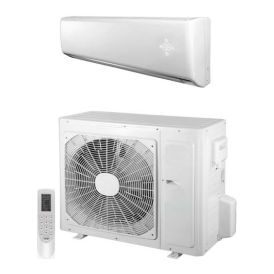
The following parts are included in your indoor unit. Please contact
your dealer if any parts are damaged or missing.
Table 1-Parts List
Parts
Mounting Plate
Mounting Hardware
Remote Control
Remote Control Holder
Battery (1.5V)
. . . . . . . . . . . . . . . . . . . . . . . . . . . . .
. . . . . . . . . . . . . . . . . . . . . . . . . . . . . .
. . . . . . . . . . . . . . . . . . . . . . . . . . .
. . . . . . . . . . . . . . . . . . . . . . . . .
. . . . . . . . . . . . . . . . . . . . .
. . . . . . . . . . . . . . . . . . . . . . .
Qty
1
7
1
1
2
PAGE
2
2
2
2
3
4
6
7
8
8
9
9
9
9
9
9
11
11
13
14
15
Advertisement
Table of Contents

Related Manuals for International comfort products DLFCAB


Summary of Contents for International comfort products DLFCAB
-
Page 1: Table Of Contents
..........PIPING AND REFRIGERANT TABLES DLFCAB / DLCCAR / DLFCHB / DLCCHR . -
Page 2: Safety Considerations
SAFETY CONSIDERATIONS WARNING Installing, starting up, and servicing air−conditioning equipment can be hazardous due to system pressures, electrical components, and ELECTRICAL SHOCK HAZARD equipment location (roofs, elevated structures, etc.). Failure to follow this warning could result in personal Only trained, qualified installers and service mechanics should install, injury or death. -
Page 3: Piping And Refrigerant Tables Dlfcab / Dlccar / Dlfchb / Dlcchr
PIPING AND REFRIGERANT TABLES DLFCAB / DLCCAR / DLFCHB / DLCCHR Table 2—Piping Information DLFCAB / DLCCAR / DLFCHB / DLCCHR System Size Voltage 115/1/60 115/1/60 208/230-1-60 208/230-1-60 208/230-1-60 208/230-1-60 208/230-1-60 208/230-1-60 Min. Piping Length Standard Piping Length Max. Outdoor- 32.8... -
Page 4: Piping And Refrigerant Tables Dlfdab / Dlcdar / Dlfdhb / Dlcdhr
PIPING AND REFRIGERANT TABLES DLFDAB / DLCDAR / DLFDHB / DLCDHR Table 4— Piping Information DLFDAB / DLCDAR / DLFDHB / DLCDHR System Size 30K* 36K* Voltage 115/1/60 115/1/60 208/230-1-60 208/230-1-60 208/230-1-60 208/230-1-60 208/230-1-60 208/230-1-60 Min. Piping Length Standard Piping Length Max. - Page 5 A separate shielded stranded copper conductor only, with a minimum 600 volt rating and double insulated copper wire, must be used as the communication wire from the outdoor unit to the indoor unit. Table 6—Electrical Data DLFCAB - DLCCAR / DLFCHB - DLCCHR System Size Voltage 115/1/60...
-
Page 6: Dimensions−Indoor
DIMENSIONS − INDOOR Fig. 1 - Indoor Unit Dimensions Table 8—DLFCAB / DLCCAR / DLFCHB / DLCCHR System Size Voltage 115/1/60 115/1/60 208/230-1-60 208/230-1-60 208/230-1-60 208/230-1-60 208/230-1-60 208/230-1-60 Height (H) 11.4 11.4 11.4 11.4 11.8 12.8 12.8 12.8 Width (W) 33.3... -
Page 7: Dimensions−Outdoor
DIMENSIONS − OUTDOOR Fig. 3 - Outdoor Unit Table 12—DLFCAB / DLCCAR / DLFCHB / DLCCHR System Size Voltage 115/1/60 115/1/60 208/230-1-60 208/230-1-60 208/230-1-60 208/230-1-60 208/230-1-60 208/230-1-60 Height (H) 21.3 23.3 21.3 23.3 27.6 31.1 31.1 31.1 Width (W) 33.4 33.4... -
Page 8: Clearances−Indoor
CLEARANCES − INDOOR CEILING 6" (0.15m) min. 5" 5" (0.13m) (0.13m) min. min. (1.8m) FLOOR Fig. 4 - Indoor Unit Clearances CLEARANCES − OUTDOOR Air-inlet Air-outlet Fig. 5 - Outdoor Unit Clearances Table 14—Outdoor Clearances UNIT Minimum Value in. (mm) 24 (609) 24 (609) 24 (609) -
Page 9: Installation Guide
If piping is going through the back: INSTALLATION GUIDE 1. Determine pipe hole position using the mounting plate as a Ideal installation locations include: template. Drill pipe hole diameter per chart below. The outside Indoor Unit pipe hole is 1/2−in. (13 mm) min. lower than inside pipe hole, so S A location where there are no obstacles near inlet and outlet area. - Page 10 Piping Guide: Outdoor Unit Wiring Connections S Do not open service valves or remove protective caps from tubing 1. Mount outdoor power disconnect. ends until all the connections are made. 2. Run power wiring from main box to disconnect per NEC and S Bend tubing with bending tools to avoid kinks and flat spots.
-
Page 11: Install All Power, Interconnecting Wiring And Piping To Indoor Unit
INSTALL ALL POWER, INTERCONNECTING Fixing hook Mounting WIRING, AND PIPING TO INDOOR UNIT plate Mounting 1. Run interconnecting piping and wiring from outdoor unit to plate indoor unit. 2. Pass interconnecting cable through hole in wall (outside to inside). 3. Lift indoor unit into position and route piping and drain through hole in wall (inside to outside). - Page 12 Triple Evacuation Method Manifold Gage The triple evacuation method should only be used when vacuum pump is only capable of pumping down to 28 in. of mercury vacuum and system does not contain any liquid water. 500 microns Refer to Fig. 19 and proceed as follows: Low side valve High side valve 1.
-
Page 13: Start−Up
START−UP Test Operation INSTALLATION AND MAINTENANCE OF FILTER Perform test operation after completing gas leak and electrical safety 1. Grasp the front panel by its two ends and lift the panel and then check. remove the air filter. 1. Push the “ON/OFF” button on Remote Control to begin testing. 2. -
Page 14: Wiring Diagrams
WIRING DIAGRAMS DLF/DLC*09&12J 115-1-60 Connection Diagram CONNECTING CABLE OUTDOOR TO INDOOR CAUTION CAUTION Attention Attention Use Copper Conductors Only Use Copper Conductors Only With Minimum 300 Volt, 2/64" With Minimum 300 Volt, 2/64" Control Thick Insulation. Thick Insulation. Power from Power from Power to Control to... -
Page 15: Troubleshooting
TROUBLESHOOTING This unit has on−board diagnostics. Error codes appear on the LED display on the front panel of the indoor unit in place of the temperature display. Error codes are also displayed on the outdoor unit microprocessor board with colored LED lights. The table below explains the error codes for both units. - Page 16 Copyright 2016 International Comfort Products Lewisburg, TN 37091 421 019420 02 Specifications subject to change without notice.
Need help?
Do you have a question about the DLFCAB and is the answer not in the manual?
Questions and answers