Table of Contents
Advertisement
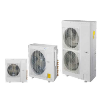
DLCBHR / DLFAHH / DLFBHB / DLFBHC / DLFBHD / DLFBHF
Multi- Zone Ductless Split System
Size 18K, 24K, 30K, 36K, 42K, 48K and 56K
NOTE: Read the entire instruction manual before starting the installation.
Installation Instructions
TABLE OF CONTENTS
. . . . . . . . . . . . . . . . . . . . . . . . . . . . . . . . . . . . . . . . .
. . . . . . . . . . . . . . . . . . . . . . . . . . . . . . . .
. . . . . . . . . . . . . . . . . . . . . . . . . . . . . . . . . . . . . . . .
. . . . . . . . . . . . . . . . . . . . . . . . . . . . . . . . . . .
. . . . . . . . . . . . . . . . . . . . . . . . . . . . . . . . .
. . . . . . . . . . . . . . . . . . . . . . . . . . . . .
. . . . . . . . . . . . . . . . . . . . . . . . . . . . . . . . . . . . . . . .
. . . . . . . . . . . . . . . . . . . . . . . . . . .
. . . . . . . . . . . . . . . . . . . . . . . . .
. . . . . . . . . . . . . . . . . . . . . . . . .
. . . . . . . . . . . . . . . . .
. . . . . . . . . .
. . . . . . . . . . . .
. . . .
. . . . . . . . . . . . . . . . . . . .
. . . . . .
. . . . . . . . . . . . . . . . . . . .
. . . . . . . . . . . . . . . . . . .
PAGE
2
2
3- 4
4
6
7- 14
15- 17
18- 19
20
20
21
24
26
28
31
35
37
38- 41
Advertisement
Table of Contents

Related Manuals for International comfort products DLCBHR


Summary of Contents for International comfort products DLCBHR
-
Page 1: Table Of Contents
DLCBHR / DLFAHH / DLFBHB / DLFBHC / DLFBHD / DLFBHF Multi- Zone Ductless Split System Size 18K, 24K, 30K, 36K, 42K, 48K and 56K Installation Instructions NOTE: Read the entire instruction manual before starting the installation. TABLE OF CONTENTS... -
Page 2: Safety Considerations
SAFETY CONSIDERATIONS WARNING Installing, starting up, and servicing air- conditioning equipment can be hazardous due to system pressures, electrical components, ELECTRICAL SHOCK HAZARD and equipment location (roofs, elevated structures, etc.). Failure to follow this warning could result in personal Only trained, qualified installers and service mechanics should injury or death. -
Page 3: System Requirements
SYSTEM REQUIREMENTS Allow sufficient space for airflow and servicing unit. See Fig. 14 through 19 for minimum required clearances. Piping IMPORTANT: Both refrigerant lines must be insulated separately. Minimum refrigerant line length between the indoor and outdoor units is 10 ft. (3 m). The following maximum lengths are allowed: Table 1—Maximum Piping Lengths Outdoor Unit System Size... -
Page 4: Electrical Data
ELECTRICAL DATA Table 8—High Wall DLFAHH SYSTEM VOLTAGE OPERATING VOLTAGE INDOOR FAN UNIT SIZE VOLT / PHASE / HZ MAX / MIN V-PH-HZ 0.0268 208-230/1/60 253 / 187 208-230/1/60 0.0268 0.0268 Table 9—High Wall DLFBHB System Voltage OPERATING VOLTAGE INDOOR FAN UNIT SIZE VOLT / PHASE / HZ MAX / MIN... - Page 5 Recommended Connection Method for Power and CAUTION Communication Wiring (To minimize communication wiring interference) EQUIPMENT DAMAGE HAZARD Power Wiring: Failure to follow this caution may result in equipment The main power is supplied to the outdoor unit. The field supplied damage or improper operation.
-
Page 6: Parts List
PARTS LIST Outdoor Units Size Name No parts included No parts included Conversion Joint 3/8 to 5/8 Conversion Joint 3/8 to 1/2 Conversion Joint 1/4 to 3/8 Screw M4X12 Conversion Joint 3/8 to 5/8 Conversion Joint 3/8 to 1/2 Conversion Joint 1/4 to 3/8 Screw M4X12 Conversion Joint 3/8 to 5/8 Conversion Joint 3/8 to 1/2... - Page 7 DIMENSIONS - INDOOR Fig. 2 - High Wall Dimensions Table 14—High Wall DLFAHH Dimensions Operating Weight Unit Size W In. (mm) D In. (mm) H In. (mm) Q In. (mm) Lbs. (kg) 37.8 (960)g 8.07 (205) 12.6 (320) 2.16 (55) 33.07 (15) 37.8 (960) 8.07 (205)
-
Page 8: Dimensions
DIMENSIONS - INDOOR (CONTINUED) Fig. 3 - Wall Dimensions Table 15—High Wall DLFBHB Unit Size W In. (mm) D In (mm) H In. (mm) Operating Weight 34.09 8.23 11.5 24.3 34.09 8.23 11.5 24.3 40.079 9.055 12.6 30.9 46.378 10.394 12.8 38.6... - Page 9 DIMENSIONS - INDOOR (CONTINUED) Fig. 4 - Cassette Grill Dimensions Fig. 5 - Cassette Side View Dimensions...
- Page 10 DIMENSIONS - INDOOR (CONTINUED) Fig. 6 - Cassette Connection Side View Dimensions Fig. 7 - Cassette Top View Dimensions...
- Page 11 DIMENSIONS - INDOOR (CONTINUED) Fig. 8 - Ducted Dimensions Table 16—Outline Dimensions Item Size 29 1/5 in 19 1/3 in 26 in 24 2/5 in 27 5/9 in 24 1/5 in 30 4/5 in 6 1/7 in 7 7/8 in 25 in (742 mm) (491 mm)
- Page 12 DIMENSIONS - INDOOR (CONTINUED) Fig. 9 - Floor Console Dimensions...
- Page 13 DIMENSIONS - OUTDOOR Fig. 10 - Outdoor Dimensions Size 18 Fig. 11 - Outdoor Dimensions Size 24...
- Page 14 DIMENSIONS - OUTDOOR (CONTINUED) Fig. 12 - Outdoor Dimensions Size 30- 42 Fig. 13 - Outdoor Dimensions Size 48- 56...
- Page 15 CLEARANCES - INDOOR CEILING 6" (0.15m) min. 5" 5" (0.13m) (0.13m) min. min. (1.8m) FLOOR Fig. 14 - High Wall Clearance Fig. 15 - Cassette Clearance...
-
Page 16: Clearances
CLEARANCES - INDOOR (CONTINUED) Fig. 16 - Ducted clearance Fig. 17 - Floor console clearance... - Page 17 CLEARANCES - OUTDOOR (CONTINUED) Air-inlet Air-outlet Fig. 18 - Clearances Outdoor 18 - 42 Table 17—Clearances Outdoor Minimum Value UNIT in. (mm) 24 (609) 24 (609) 24 (609) 4 (101) 4 (101) Fig. 19 - Clearances Outdoor 48- 56...
-
Page 18: Dimensions - Branch Boxes
DIMENSIONS - BRANCH BOXES (REQUIRED ON SIZES 48 AND 56) OUTLINE DIMENSION AND SERVICING SPACE OF KSAUI0201AAA 17 2/7 in (439 mm) 15 in (383 mm) 2 1/3 in (60 mm) 7 1/7 in (105 mm) 14 1/5 in (361 mm) 5 in (128 mm) 5 in (128 mm) 3 4/7 in (91 mm) 3 1/7 in (80 mm) - Page 19 OUTLINE DIMENSION AND SERVICING SPACE OF KSAUI0401AAA 17 2/7 in (439 mm) 15 in (383 mm) 2 1/3 in (60 mm) 7 1/7 in (105 mm) 14 1/5 in (361 mm) 1 4/5 in (35 mm) 2 3/4 in (70 mm) 2 3/4 in (70 mm) 5 in (128 mm) 5 in (128 mm)
-
Page 20: Installation Guide
INSTALLATION GUIDE If piping is going through the back: 1. Determine pipe hole position using the mounting plate as a Up to nine fan coil units can be connected to one outdoor unit. template. Drill pipe hole diameter per chart below. The Refer to the Product Data for approved combinations. -
Page 21: Ducted Indoor Units Installation
DUCTED INDOOR UNITS INSTALLATION INSTALLATION OF THE INDOOR DUCTED UNIT CAUTION Requirements on the Installation Location 1. Ensure the hanger is strong enough to withstand the weight S Prior to the installation, make a good preparation for all piping of the unit. (refrigerant pipe, drain pipe) and wiring (wires of the wired 2. - Page 22 INSTALL THE ROUND AIR SUPPLY DUCT Fig. 33 - Return Air Inlet Table 25—Dimensions of the Air Supply Outlet and Return Air Inlet (unit: in/mm) Item Air Supply Outlet Return Air Inlet Fig. 31 - Air supply duct Size 6 1/7 in 26 in (662 22 5/6 in 22 5/6 in...
- Page 23 INSTALLATION OF THE CONDENSATE PIPE 5. Insert the drain hose into the drain hole and tighten it with clamps. 1. The condensate pipe should keep a inclination angle of 5 ~ 6. Wrap the clamps with large amount of sponge for thermal 10”, to facilitate the drainage of the condensate water.
-
Page 24: Floor Console Indoor Units Installation
FLOOR CONSOLE INDOOR UNITS Location for securing the installation panel INSTALLATION Follow these key steps when selecting a location for the unit. Select a place where cool air can be distributed throughout the room. Select a place where condensation water is easily drained away. -
Page 25: Drain Piping
DRILLING A WALL HOLE AND INSTALLING WALL EMBEDDED PIPE For walls containing metal frame or metal board ,be sure to 1 7/9 in (45 mm) use a wall embedded pipe and wall cover in the 3 in (75 mm) 3 in (75 mm) Left back piping Right back piping Left/right piping... -
Page 26: Installing The Indoor Unit
INSTALLING THE INDOOR UNIT For Side Piping Remove the pillars. 1. Preparation (1.) Remove the 7 screws. Open the front panel, remove the 4 screws and dismount (2.) Remove the upper casing (2 tabs). the front grille while pulling it forward. (3.) Remove the left and right casings (2 tabs on each 3 tabs side). - Page 27 The mounting plate should be installed on a wall which can support the weight of the indoor unit. (1.) Temporarily secure the mounting plate to the wall, make sure that the panel is completely level, and mark the boring points on the wall. (2.) Secure the mounting plate to the wall with screws.
-
Page 28: Cassette Type Indoor Unit Installation
CASSETTE TYPE INDOOR UNIT INSTALLATION 59 in (1500 mm) 59 in (1500 mm) 10 1/4 in in/mm (260 mm) Fig. 57 - Schematic diagram of installation spaces Select install location of the indoor unit 25 3/5 in (650 mm) 22 4/9 in (570 mm) 1. - Page 29 Hoisting the main body of the air conditioner DRAINAGE HOSE The primary step for installing the indoor unit. 1. Install the drain hose. When attaching the hoisting stand on the hoisting screw, do The diameter of the drain hose should be equal or bigger use nut and gasket individually at the upper and lower of than the connection pipe’s.
- Page 30 INSTRUCTION The power cord reference power cord standard recommending table. The slant gradient of the attached drain hose should be within 3 in. (75 mm) so that the drain hole does not have to endure unnecessary outside force. Fig. 64 - Slant gradient Fig.
-
Page 31: Outdoor Unit Installation
OUTDOOR UNIT INSTALLATION NOTE: (1.) Improper screwing of the screws may cause issues 1. Use a rigid base to support unit in a level position. as shown in Fig. 69. 2. Locate outdoor unit and connect piping and wiring. CAUTION Air leak Air leak from ceiling EQUIPMENT DAMAGE HAZARD... - Page 32 INSTALL ALL POWER AND INTERCONNECTING NOTE WIRING TO OUTDOOR UNIT* *Branch Boxes required on sizes 48 and 56. Strong Separate power connection is required for the Outdoor unit wind and the Branch Boxes. Refer to Branch Box installation instructions. A07350 Fig.
- Page 33 OUTDOOR UNIT INSTALLATION SIZES 48 AND 56 For sizes 48 and 56, one outdoor unit can drive up to three Branch Box (BU) modules and nine different types of indoor units (high wall, cassette, ducted and floor console). At least one Branch Box (KSAUI0201AAA up to 2 indoor units or KSAUI0401AAA up to 3 indoor units) is required on these sizes.
- Page 34 CONNECTION DIAGRAMS 18-42 Fig. 75 - Connection Diagram Sizes 18- 42 48-56 Fig. 76 - Connection Diagram Sizes 48- 56 Connection Diagram Fig. 77 - Connection Diagram Branch Box...
-
Page 35: System Vacuum And Charge
INSTALL ALL POWER, INTERCONNECTING SYSTEM VACUUM AND CHARGE WIRING, AND PIPING TO INDOOR UNIT. CAUTION 1. Run interconnecting piping and wiring from outdoor unit to each indoor unit (in matched pairs) (except sizes 48 and 56 refer to Branch Box installation instructions). UNIT DAMAGE HAZARD 2. - Page 36 Deep Vacuum Method Triple Evacuation Method The deep vacuum method requires a vacuum pump capable of The triple evacuation method should only be used when vacuum pulling a vacuum of 500 microns and a vacuum gage capable of pump is only capable of pumping down to 28 in. of mercury accurately measuring this vacuum depth.
-
Page 37: Start- Up
START- UP Test Operation Explain The Following Items To Customer With The Aid Of The Owner’s Manual: Perform test operation after completing gas leak and electrical 1. How to turn air conditioner on and off; selecting safety check. COOLING, HEATING and other operating modes; setting 1. -
Page 38: Troubleshooting
TROUBLESHOOTING This unit has on- board diagnostics. Error codes are displayed on the wired remote controller and the outdoor unit microprocessor board with colored LED lights. The table below explains the error codes on both. SIZES 18 & 24 Table 27—Malfunction Status Table Nixie Malfunction name Malfunction type... - Page 39 TROUBLESHOOTING This unit has on- board diagnostics. Error codes are displayed on the wired remote controller and the outdoor unit microprocessor board with colored LED lights. The table below explains the error codes on both. SIZES 30, 36 & 42 Table 28—Malfunction Status Table The indicator display Name of malfunction...
- Page 40 TROUBLESHOOTING This unit has on- board diagnostics. Error codes are displayed on the wired remote controller and the outdoor unit microprocessor board with colored LED lights. The table below explains the error codes on both. SIZES 48 - 56 Table 29—Malfunction Status Table Main control display for outdoor unit Errors of definition Indoor unit code...
- Page 41 TROUBLESHOOTING (CONTINUED) This unit has on- board diagnostics. Error codes are displayed on the wired remote controller and the outdoor unit microprocessor board with colored LED lights. The table below explains the error codes on both. SIZES 48 - 56 Main control display for outdoor unit Errors of definition Indoor unit code Testing board...
- Page 42 Flash 6 times b5+ indoor unit address Catalog No:OG - DLCBHB- 01 Copyright 2015 International Comfort Products Lewisburg, TN 37091 USA Edition Date: 07/15 Replaces:NEW Manufacturer reserves the right to change, at any time, specifications and designs without notice and without obligations.
Need help?
Do you have a question about the DLCBHR and is the answer not in the manual?
Questions and answers