Table of Contents
Advertisement
Quick Links
Advertisement
Table of Contents

Related Manuals for Innova eHPoca


Summary of Contents for Innova eHPoca
-
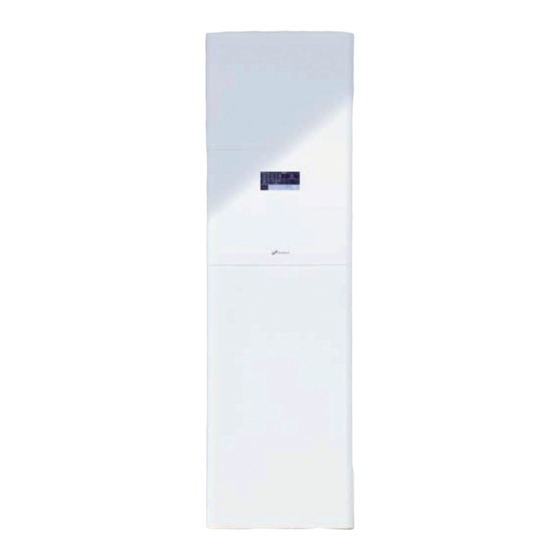
Page 1: Base Unit
3in1 TECHNICAL MANUAL... -
Page 3: Table Of Contents
/ 3in1 SOMMARIO GENERAL INFORMATION . . . . . . . . . . . . . . . . . . . . . . . . . . . . . . . . . . . . . . . . . . . . . . . 6 A look to the future . - Page 4 Innova 3in1 . . . . . . . . . . . . . . . . . . .
- Page 5 / 3in1 External unit dimensions . . . . . . . . . . . . . . . . . . . . . . . . . . . . . . . . . . . . . . . . . . . . . . . . . . . . . . . 102 Notes on Installation .
-
Page 6: General Information
Directive 2009/28/EC of the European Parliament and of the Council of 23 April 2009 on the promotion of the use of energy from renewable sources defines the “environmental heat” in the Air, Water and Earth as renewable source of energy. eHPoca and 3in1 of INNOVA use the environmental heat and the Heat Pump principle to generate and distribute heat-transfer fluids that render the living environments comfortable throughout the whole year. -
Page 7: The Heat Pump
According to Directive (2002/91/EC) of the European Parliament and of the Council, all building should have an energy perfor- mance certificate considering the primary energy. Used on the same building, eHPoca and 3in1 reduce the primary energy con- sumption levels by at least 50% compared to the traditional boiler solutions, reaching higher performance classes, increasing therefore the property’s value, with an average return of investment of 3-4 years. - Page 8 By configuring the web server with the data of your connection, you will be able to receive e-mails whe- never an alarm occurs. You will also be able to see, check and control many other devices INNOVA connected to the same ethernet network, such as AIRLEAF and FILOMURO fancoils.
-
Page 9: The Heat Pump
After observing the previous point, make sure that the storage temperature does not exceed 47 °C, except in special cases. Choose the power purchase agreement that suits you best; request the special rates using the INNOVA declaration, and you will benefit from a fixed price contract, without tariff increase due to consumption bands. - Page 10 OPERATION The functioning principle of the heat pump is similar to that of a regular refrigerator that takes the heat from the refrigerator compartment and releases it into the ambient; you can perceive the heat by touching the heating element outside the fridge, which represents the condenser.
- Page 11 The heat pumps INNOVA can produce hot water up to 55 °C, allowing you to use the units in any installation that requires sa- nitary hot water.
-
Page 12: Types
5% to 13% of the total thermal energy produced by the heat pump. The INNOVA air-water Heat pumps use an Inverter-controlled DC compressor which in combination with the electronic expansion valve and a sophisticated algorithm, enable optimising the pump’s operation at low temperatures, adjusting the flow of refrigerant fluid to minimise the number of defrost cycles and their duration, greatly reducing the average percentage indicated above. - Page 13 You have to evaluate well the payback. However, the INNOVA Geothermal pumps in the GEO series are fitted with Inverter-controlled DC compressor and with a control system that can coordinate all the components of the machine and of the system, ensuring maximum efficiency.
-
Page 14: Efficiency
DC Inverter technology and to the fact that the temperature of the generated water varies based on the temperature of the outdoor air . The following table shows the seasonal coefficient of performance (SCOP) of eHPoca and 3in1 for each climate zone and type of heating system, as per standard EN 14825:... - Page 15 According to the standard, SEER must be calculated for both types of distribution systems defined by the standard. INNOVA pumps ensure high seasonal energy efficiency in cooling season too, the values can be found in the table at p.
- Page 16 REASONS FOR USING THE HEAT PUMP Primary energy use In terms of primary energy savings (oil, gas, coal, uranium), the heat pump is convenient because it provides better global yields than the traditional systems. In fact, heating by means of heating elements is not an economic application of the primary energy, as its relative global yield does not exceed 30%.
- Page 17 / 3in1 Cost-effectiveness From a management perspective, a heat pump system used for ambient heating allows significant savings. The extent of these savings is related to the performances of the installed heat pump, that depend on certain parameters. First of all, the heat pump’s operating range is economically much more competitive as:...
-
Page 18: Sizing Directions
The heat pumps INNOVA fitted with DC Inverter compressor can easily meet the majority of the heat demands as it is able to modulate its output in a continuous manner, from 20% to 130% (for some models even 150%!). - Page 19 / 3in1 Monovalent systems A monovalent configuration is used when the heat pump does not require auxiliary heating systems. In this case, the heat pump meets the heating requirements fully. In monovalent configurations, the heat pumps are sized considering the unit’s heating capacity in the worst environmental conditions.
- Page 20 0 °C and water temperature 35 °C. 3in1 air / water heat pump If you set up an air/water heat pump series eHPoca in the same application, the yielded heat will become: PLR Part load ratio (Thermal power/Pdesign) Outdoor (or source, air) temperature...
- Page 21 (see the next paragraph); otherwise, if the unit is installed in less rigid climates (typical for Central and South European countries) you can choose a monovalent configuration. Usually, you should consider a bivalent configuration for air/water units INNOVA if the external design temperatures drop below -4 °C.
- Page 22 If we list in the chart below the heating capacities of models 9, 12 and 15, we will obtain the following: PLR Part load ratio (Thermal power/Pdesign) Outdoor (or source, air) temperature 3in1 model 15 3in1 model 12 3in1 model 9 Building heat transfer (kW) 16,00...
- Page 23 / 3in1...
- Page 24 NOTES...
- Page 25 NOTES...
- Page 26 Set the daily and weekly time bands along with the ope- means of an ethernet cable into another room or you can rating mode and the relevant setpoints. use it wirelessly as long as you keep it in the range of a WIFI network. ehpoca...
-
Page 27: Innova Ehpoca
The heat pump eHPoca is designed to achieve the required eHPoca it consists of an indoor unit and of an outdoor unit. performance with maximum efficiency and flexibility:.In fact, with our range of tanks and boilers it can meet even... -
Page 28: Connectivity
inspection. -
Page 29: Description
DC cir- Pipings and all internal components of eHPoca are insulates culator pump (class A), 6 litres plant expansion vessel, safe- so as to avoid any leakage or due in summer cycle, the elec-... -
Page 30: External Unit
EXTERNAL UNIT Outdoor units belong to the same eHPoca range (up to 15 kW model), functioning from –20 °C to + 45 °C, starting from water temperatures of 5 °C, without requiring additional heaters, modulating full inverter control, perfect defrosting cycles in every outdoor condition and very low noise level, gas connections can be up to 50 meters. -
Page 31: Codes
CODES For the classification of the different models, we will use a reading key that allows us to identify the specific characteri- stics and functions of the different models. Feature Code Value Type Heat pump Range eHPoca Size Internal... -
Page 32: Manufacturing Details
MANUFACTURING DETAILS INTERNAL UNIT Internal unit components Automatic air relief valve Refrigerant connections Heater manifold Circulator pump P1 Main switch Pressure gauge Emergency control Touch LCD display Electrical panel Safety valve (6 bar) Liquid receiver 6 L Expansion vessel Plate heat exchanger External unit control Differential pressure switch Internal heat exchanger... - Page 33 Primary pump P1 The pump can also run in “continuous” mode (the pump runs continuously for as long as the tool is enabled) or timmed “energy saving” mode (the pump starts when prompted by the regulator and once every 2 minutes of ON and 15 minu- tes of OFF if the regulator’s demand is met);...
- Page 34 stem. After filling the system and releasing the air, make In order to prevent any dangerous overheating, besides sure the pressure does not exceed 1.5 BAR when the machi- the electronic temperature sensors which interact with the ne is stopped or in cooling mode. electronic card, we installed a bulb thermostat with expan- ding liquid that stops its operation in case of any electronic device malfunction.
- Page 35 EXTERNAL UNIT Sizes 7 - 9 Connections input Sizes 12 - 15 - 18 - 24 Electric fans Access panel Cover Refrigerant connections 12-15 External unit components External panels Compressor Heat exchanger Electric fan Cycle reversing valve Panels tions. On all models the compressor is covered in sound- proofing material to reduce the noise.
- Page 36 External heat exchanger Depending on the model, the compressors can be single- phase or three-phase. It is a battery made of copper pipes (for refrigerant circula- The engine is a DC hermetic engine with permanent magnet tion) and aluminium fins for heat transfer with air The surfa- rotor and adjustable speed drive.
- Page 37 Therefore, the amount of fluid to be expanded is not con- stant, but it should be perfectly balanced in order to avoid any excessive or insufficient powering of the evaporator. In practice, the cooling circuit section ”restriction” that al-...
-
Page 38: Control Logics
CONTROL LOGICS FUNCTIONING PRINCIPLE Based on the readings from the return temperature (T1) ve and waiting for another minute before reactivating the and the sanitary water (T3) sensors, on the setpoints, on pump, the ON/OFF outputs and the heater (if previously on). the external temperature measured by the T4 sensor and In case of an alarm condition, the 3-way valve output is disa- on the status of the inlets, the electronic card shall make all... -
Page 39: Climate Regulation
In the units fitted with auxiliary element, the Q2 switch di- sables and electrically protects the unit. The installer can Risc. connect the three stages (2, 4 or 6 kW) according to the re- ausiliario quirements of and the electrical power available to the user. -
Page 40: Technical Specifications
In order to provide the correct nominal data, the test shall be carried out at rating fre- quency, which is the frequency that the manufacturer considers nominal. This principle applies because the heat pumps INNOVA are equipped with DC Inverter compressor; this option is not available on the On-Off machines. -
Page 41: Part Load Performance In Cooling
SIZING TABLE OF THE POWER SUPPLY LINE Models Voltage V/50Hz 400-3N 400-3N 400-3N 400-3N Maximum input power (1) 3.93 3.93 5.55 5.85 6.20 6.50 7.15 7.60 Maximum input current (1) 12.5 Maximum input power (2) 9.93 9.93 11.55 11.85 12.20... - Page 42 PART LOAD PERFORMANCE IN HEATING The performances indicated below refer to specific and different environmental conditions, with the compressor set at rating frequency. T. a Mod. T. ae 3.14 1.53 2.05 3.04 1.72 1.77 2.95 1.96 1.50 2.85 2.24 1.27 2.75 2.57 1.07...
- Page 43 The values are automatically ensured in “Boost” phase or in sanitary hot water production, allowing a better performance compared to the nominal data. This means that eHPoca offers a “Plus” that allows compensating for point loads, a feature im- possible to achieve by means of On-Off compressors.
- Page 44 The values are automatically ensured in “Boost” phase or in sanitary hot water production, allowing a better performance compared to the nominal data. This means that eHPoca offers a “Plus” that allows compensating for point loads, a feature im- possible to achieve by means of On-Off compressors.
- Page 45 EHPOCA SPECIFICATION CHARTS / BUILDING ACCORDING TO STANDARD UNI EN 14825 The charts in the following chapter show the capacities of the eHPoca heat pumps as a function of part load and the resulting heating demand of the building, for “average” reference climate zone (external design temperature -10 °C).
- Page 46 12M - 12T Model (°C) PLR Part load ratio Outdoor (or source, air) temperature Thermal power/Pdesign ratio Building heat transfer Bivalent point 15M - 15T Model (°C) PLR Part load ratio Outdoor (or source, air) temperature Thermal power/Pdesign ratio Building heat transfer Bivalent point...
- Page 47 18T Model (°C) PLR Part load ratio Outdoor (or source, air) temperature Thermal power/Pdesign ratio Building heat transfer Bivalent point 24T Model (°C) PLR Part load ratio Outdoor (or source, air) temperature Thermal power/Pdesign ratio Building heat transfer Bivalent point...
-
Page 48: Energy Efficiency In Heating As Per Standard En 11300
ENERGY EFFICIENCY IN COOLING AS PER STANDARD EN 11300 The values below are requested by standard EN 11300, as they show the correct relation between the building and the system, necessary for the energy performance certificate. T.ae / °C 35 / 7 30 / 7 25 / 7 20 / 7... -
Page 49: Flow Charts / Circulator Pump Head
FLOW CHARTS / CIRCULATOR PUMP HEAD Models 7 - 9 A (kPa) Taglia 7 Taglia 9 B (m³/h) Residual pressure head Flow rate Model 12 A (kPa) B (m³/h) Residual pressure head Flow rate... - Page 50 Models 15 - 18 A (kPa) Taglia 15 Taglia 18 B (m³/h) Residual pressure head Flow rate Model 24 A (kPa) B (m³/h) Residual pressure head Flow rate...
-
Page 51: Operating Limits
OPERATING LIMITS External temperature (°C) PDC off. Heating by means of backup heater, boiler or Heating and SHW production mode solar panels Cooling mode Sanitary water tank temperature (°C) Water temperature (°C) Backup heat from heater or boiler –20... -
Page 52: Ethylene Glycol Solutions
SYSTEM WATER REFERENCE VALUES System water reference values 6.5 ÷ 7.8 Electrical conductivity µS/cm 250 ÷ 800 Total hardness °F 5 ÷ 20 Total iron Manganese < 0.05 Chlorides < 250 Sulphur ions none Ammonia ions none If the total hardness of the return water exceeds 20 °F or some of its reference values do not fall within the specified limits, please contact our after sales service for advice. - Page 53 EXTERNAL UNIT NOISE LEVELS MOD. 7 MOD. 7 Livello di potenza sonora Raffreddamento 48 dB(A) Livello di potenza sonora Riscaldamento 50 dB(A) Condizioni 1m di fronte e all’altezza di 1,5m Condizioni 1m di fronte e all’altezza di 1,5m Sorgente...
- Page 54 MOD. 18 MOD. 18 Livello di potenza sonora Raffreddamento 54 dB(A) Livello di potenza sonora Riscaldamento 55 dB(A) Condizioni 1m di fronte e all’altezza di 1,5m Condizioni 1m di fronte e all’altezza di 1,5m Sorgente 220-230-240V, 1 phase, 50Hz Sorgente 220-230-240V, 1 phase, 50Hz Raffreddamento Riscaldamento...
-
Page 55: External Unit Dimensions
INTERNAL UNIT DIMENSIONS Models Width (B) Height (A) Depth (C) Net weight EXTERNAL UNIT DIMENSIONS Models Width (B) Height (A) 1416 1416 1416 1416 1416 1526 Depth (C) Net weight... - Page 56 HYDRAULIC CONNECTIONS The hydraulic connections should be completed by installing: – air relief valves at the highest points of the pipes; – flexible elastic joints; – on/off valves. The hydraulic connections are positioned in the upper part of the unit. The hydraulic connections can be positioned either to the wall (hiding them from sight) or upwards.
-
Page 57: Notes On Installation
Among these accessories, there are sanitary hot water boi- eHPoca of INNOVA meet any heating and cooling demand. lers that can be connected not only to eHPoca, but also to The eHPoca electronic control allows the connection of ba- solar thermal collectors. - Page 58 (typical for centralised systems) Domestic hot water user Outside temperature probe Radiant system Climate controller Fancoils system Thermostat Water line Non-return valve Safety valve (6 bar) P3 Pump Line filter for cold water System expansion vessel...
- Page 59 Radiant system Non-return valve Fancoils system P3 Pump Water line System expansion vessel Safety valve (6 bar) eHPoca Internal unit Line filter for cold water Solar panel 5 L Expansion vessel Solar control unit Cold water manifold Solar station pump P9...
- Page 60 Domestic hot water user Non-return valve Radiant system P3 Pump Fancoils system System expansion vessel Water line eHPoca Internal unit Safety valve (6 bar) Solar panel Line filter for cold water Solar control unit 5 L Expansion vessel Solar station pump P9...
-
Page 61: Installation Of The Internal Unit
INSTALLATION OF THE INTERNAL UNIT Positioning Minimum clearances and access to internal parts Lower panel Central door Upper panel Electrical panel 500 mm 200 mm 200 mm 500 mm... -
Page 62: Installation Of The External Unit
INSTALLATION OF THE EXTERNAL UNIT Clearance ≥15 ≥25 ≥20 ≥50 Anti-vibration dampers available as accessories (kit GR0672) Min. 15cm Maximum allowed length Height difference limit between the 2 units if the external unit is installed at a higher position Height difference limit between the 2 units if the external unit is installed at a lower position Length of the connection pipes 3/8’’... -
Page 63: Connections To The Terminal Strip
CONNECTIONS TO THE TERMINAL STRIP Terminal block U1 U2 EXT. UNIT LB0656 Terminals 1-2: serial connection of external unit terminals During execution of the anti-Legionella function the cooling U1 and U2 (by the installer). Unpolarised connection. Use a and heating requirements of the system are not satisfied. -
Page 64: Ethernet Connection Via Switch Or Hub
Outside temperature probe attic outside temperature probe under a terrace protective box if free wall provide a small roof terminal block ETHERNET CONNECTION VIA SWITCH OR HUB The touch screen interface is connected to the INN-PDC-02 this message you will have the possibility to notify your af- controller by means of a web server ethernet board that ter sales service that will be able to connect to in order to can be connected to a switch and a modem, allowing you to... -
Page 65: Accessories
ACCESSORIES SOLAR UNIT Solar control unit (board) The input and outputs of the set system are automatical- ly controlled by the control unit, according to the following logic: – The PSO pump is enabled when S1 – S2 > 8 °C. - Page 66 300-400 L Heating flow 1” 1/2 Heat source return 1” 1/2 Service fitting 1” 1/2 Heating return 1” 1/2 electrical heater presetting 1” 1/2 Service fitting 1” 1/2 Solar flow 1” Heat source flow 1” 1/2 Low temperature heating return 1” 1/2 SHW outlet 1”...
- Page 67 500 ÷ 1500 L SHW outlet 1” 1/2 Biomass boiler flow 1 "1/2 Service fitting 1” 1/2 Heating return 1” 1/2 Solar flow 1” Thermometer or probe 1/2” Electrical heater presetting 1” 1/2 Heating flow 1” 1/2 Solar return 1”...
-
Page 68: General Features
1000 1500 Tank technical specifications General features Tank capacity 1000 1500 Material: S 235 Jr S 235 Jr S 235 Jr S 235 Jr Insulation thickness Test pressure Maximum operating pressure Maximum temperature °C Heat loss kWh/24h 3.44 3.38 3.44 3.77 Straightening height 2040... - Page 69 Puffer Storage of water coming from conditioning and cooling sy- stems, also suitable for hot water systems. Used in civil and industrial air conditioning and cooling systems. User input/output User input/output Thermometer or probe Thermometer or probe User input/output...
- Page 70 NOTES...
- Page 71 NOTES...
- Page 72 3in1...
-
Page 73: Innova 3In1
3in1 INNOVA 3IN1 3in1 is a pre-assembled heating and cooling unit that uses summer cooling renewable energy and contains most of the system compo- the production and accumulation of sanitary hot wa- nents, perfectly coordinated and integrated to ensure with... - Page 74 Standby Active alarm warning and reset Winter heating mode Circulator pump operation P1 Summer cooling mode Auxiliary heating system operation Date and time Hours of operation for auxiliary heating Settings Hours of operation for heat pump Summer/winter air temperatures. Access to settings System water temperature probe page.
-
Page 75: Connectivity
You can also control all INNOVA machines online, such normally compatible only with a few hardware devices, the as AIRLEAF and FILOMURO fan coils for a very low addi- 3in1 interface is HTML, the language used to create web pa- tional charge. -
Page 76: Description
DESCRIPTION Plant circulator pump P2 Hydraulic separator Heat pump circulator pump P1 Manifold Pressure gauge Plate heat exchanger Solar safety valve 4 bar Sanitary three-way valve Solar pressure gauge * Solar control unit * PSO solar circuit pump * Touch LCD display * Drain cock 6 kW Heater Sanitary hot water tank... -
Page 77: External Unit
3in1 INTERNAL UNIT 3in1 appropriate for winter heating, summer cooling and Connections for an auxiliary boiler (for hybrid solutions) sanitary hot water production. and/or medium temperature radiators (towel warmers) The internal module, marked by nice design and reduced are as well available. This solution allows to maintain very dimensions, contains: brazed plates heat exchanger, DC in- low water temperatures for the primary circuit and to feed verter (class A) circulator pump on primary circuit, 200 litres... -
Page 78: Codes
White Single-phase for internal (indoor) unit Three-phase for internal (indoor) unit Electrical power supply Single-phase for external (outdoor) unit Three-phase for external (outdoor) unit Brand INNOVA Country of destination Italy BASE UNIT Internal unit External unit Nominal capacity Power supply... -
Page 79: Additional Modules
3in1 ADDITIONAL MODULES Additional modules for all models (factory configuration) GB0683II Secondary Hydraulic unit: hydraulic separator, water pump (DC Inverter class A) and fittings GB0684II 6 kW heaters (3 steps of 2 kW) GB0685II Solar unit: control unit, pump, safety valve, 24 litres expansion vessel, charge unit Plant circulator pump P2 Solar charge unit Hydraulic separator... -
Page 80: Manufacturing Details
MANUFACTURING DETAILS INTERNAL UNIT Internal unit components Plant circulator pump P2 * Safety valve (6 bar) Heat pump circulator pump P1 Automatic air relief valve Pressure gauge Hydraulic separator Solar safety valve 4 bar Manifold Solar pressure gauge * Plate heat exchanger PSO solar circuit pump * DHW three-way valve Drain cock... - Page 81 3in1 Internal heat exchanger The pump installed on the primary circuit P1 (inverter class A) turns on after receiving a hot water request (signalled by The internal unit is fitted with high-efficiency brazed plates the T3 sensor located in the SHW tank) or a system request heat exchanger made of stainless steel.
- Page 82 Heat exchanger water circulation differential pressure switch A differential pressure switch is connected to the inlet and outlet of the internal heat exchanger. Its operation is based on the principle that an appropriate water circulation inside the plates heat exchanger leads to a consequent pressure drop (difference between water inlet and outlet).
- Page 83 3in1 – the constant head (number of revolutions) mode (factory The maximum allowed lod losses must match the resi- default) in which the pressure generated by the pump is dual head available on the pump installed on the machi- kept constant at the value set throughout the range of flow rate permitted (this mode is suitable for systems Hydraulic separator with constant pressure drops or 3 way bypass valves).
- Page 84 Preset system Variable head Solar panels probe Sanitary hot water tank probe OUT1 Output for solar pump PSO H max H min PSO solar circuit pump The setting of maximum head for PSO solar pump is then performed with compressor capacity 100%, all distribution The high efficiency wet-rotor circulator pump for PSO solar valves opened and the utilities turned on by checking that circuit (inverter class A) ensures an operating range from -0...
- Page 85 3in1 Constant head modes (for ambient heating ot for sanitary hot water pro- duction). In order to prevent any dangerous overheating, besides the electronic temperature sensors which interact with the electronic card, we installed a bulb thermostat with expan- ding liquid that stops its operation in case of any electronic device malfunction.
- Page 86 EXTERNAL UNIT Access panel Electric fans Refrigerant connections Cover Connections input 12-15 External unit components Access panel Refrigerant connections Connections input Electric fans Cover 12-15...
- Page 87 3in1 External panels Compressor Heat exchanger Electric fan Cycle reversing valve Panels overloads, overvoltage, overheating or errors in the three- phase power supply sequence. The cover is made of epoxy-polyester painted galvanised steel sheet panels (resistant to UV rays and to weather con- ditions), dried in oven at 180 °C.
- Page 88 External heat exchanger Therefore, the amount of fluid to be expanded is not con- stant, but it should be perfectly balanced in order to avoid It is a battery made of copper pipes (for refrigerant circula- any excessive or insufficient powering of the evaporator. tion) and aluminium fins for heat transfer with air The surfa- In practice, the cooling circuit section ”restriction”...
-
Page 89: Control Logics
3in1 CONTROL LOGICS FUNCTIONING PRINCIPLE Based on the readings from the return temperature (T1) ve and waiting for another minute before reactivating the and the sanitary water (T3) sensors, on the setpoints, on pump, the ON/OFF outputs and the heater (if previously on). the external temperature measured by the T4 sensor and In case of an alarm condition, the 3-way valve output is disa- on the status of the inlets, the electronic card shall make all... -
Page 90: Climate Regulation
In the units fitted with auxiliary element, the Q2 switch di- sables and electrically protects the unit. The installer can Risc. connect the three stages (2, 4 or 6 kW) according to the re- ausiliario quirements of and the electrical power available to the user. Consult the table of power absorption for the various conditions and add the power of the heaters connected in order to determine the size of the electrical system. -
Page 91: Technical Specifications
In order to provide the correct nominal data, the test shall be carried out at rating fre- quency, which is the frequency that the manufacturer considers nominal. This principle applies because the heat pumps INNOVA are equipped with DC Inverter compressor; this option is not available on the On-Off machines. -
Page 92: Part Load Performance In Cooling 9
SIZING TABLE OF THE POWER SUPPLY LINE Models Voltage V/50Hz 400-3N 400-3N Maximum input power (1) 3.93 3.93 5.55 5.85 Maximum input current (1) Maximum input power (2) 9.93 9.93 11.55 11.85 12.2 12.5 Maximum input current (2) 17.7 18.7 Version without heater Version with 6kW heater PART LOAD PERFORMANCE IN COOLING... - Page 93 3in1 PART LOAD PERFORMANCE IN HEATING The performances indicated below refer to specific and different environmental conditions, with the compressor set at rating frequency. T. a Model T. ae 3.14 1.53 2.05 3.04 1.72 1.77 2.95 1.96 1.50 2.85 2.24 1.27 2.75 2.57...
- Page 94 MAXIMUM PART LOAD PERFORMANCE IN COOLING The values below are the actual outputs achieved by the heat pump 3in1 INNOVA at maximum DC Inverter power supply fre- quency. The values are automatically ensured in “Boost” phase or in sanitary hot water production, allowing a better performance com- pared to the nominal data.
- Page 95 3in1 MAXIMUM PART LOAD PERFORMANCE IN HEATING The values below are the actual outputs achieved by the heat pump 3in1 INNOVA at maximum DC Inverter power supply fre- quency. The values are automatically ensured in “Boost” phase or in sanitary hot water production, allowing a better performance com- pared to the nominal data.
- Page 96 As per the standard, this test should be carried out at rated frequency and therefore, without storage tank, a regular heat pump generates excessive or insufficient power with regard to the demand. In fact, by increasing or decreasing the frequency, INNOVA 3in1 can adapt its output to the building’s heating demand, saving storage and installation space.
- Page 97 3in1 12M - 12T Model (°C) PLR Part load ratio Outdoor (or source, air) temperature Thermal power/Pdesign ratio Building heat transfer Bivalent point 15M - 15T Model (°C) PLR Part load ratio Outdoor (or source, air) temperature Thermal power/Pdesign ratio Building heat transfer Bivalent point...
-
Page 98: Energy Efficiency In Heating As Per Standard En 11300
ENERGY EFFICIENCY IN COOLING AS PER STANDARD EN 11300 The values below are requested by standard EN 11300, as they show the correct relation between the building and the system, necessary for the energy performance certificate. T.ae / °C 35 / 7 30 / 7 25 / 7 20 / 7... -
Page 99: Operating Limits
3in1 OPERATING LIMITS External temperature (°C) PDC off. Heating by means of backup heater, boiler or Heating and SHW production mode solar panels Cooling mode Sanitary water tank temperature (°C) Water temperature (°C) Backup heat from heater or boiler –20 –25... -
Page 100: Ethylene Glycol Solutions
SYSTEM WATER REFERENCE VALUES System water reference values 6.5 ÷ 7.8 Electrical conductivity µS/cm 250 ÷ 800 Total hardness °F 5 ÷ 20 Total iron Manganese < 0.05 Chlorides < 250 Sulphur ions none Ammonia ions none If the total hardness of the return water exceeds 20 °F or some of its reference values do not fall within the specified limits, please contact our after sales service for advice. - Page 101 3in1 EXTERNAL UNIT NOISE LEVELS MOD. 7 MOD. 7 Livello di potenza sonora Raffreddamento 48 dB(A) Livello di potenza sonora Riscaldamento 50 dB(A) Condizioni 1m di fronte e all’altezza di 1,5m Condizioni 1m di fronte e all’altezza di 1,5m Sorgente 220-230-240V, 1 phase, 50Hz Sorgente 220-230-240V, 1 phase, 50Hz...
-
Page 102: External Unit Dimensions
INTERNAL UNIT DIMENSIONS Models Width (B) Height (A) 2000 2000 2000 2000 2000 2000 Depth (C) Net weight EXTERNAL UNIT DIMENSIONS Models Width (B) Height (A) 1416 1416 1416 1416 Depth (C) Net weight... - Page 103 3in1 HYDRAULIC CONNECTIONS The hydraulic connections should be completed by installing: – air relief valves at the highest points of the pipes; – flexible elastic joints; – on/off valves. The hydraulic connections are positioned in the upper part of the unit. The hydraulic connections can be positioned either to the wall (hiding them from sight) or upwards.
- Page 104 Boiler Heater manifold * Sanitary hot water user Heat pump circulator pump P1 High temperature utilities (towel warmer) 3-way valve Plant utilities Boiler air relief valve 24 L Expansion vessel Solar charge valve * Safety valve (7 bar) Solar safety valve 4 bar * Thermostatic mixing valve * Pressure gauge * High temperature circulator pump P3 *...
-
Page 105: Notes On Installation
The system layouts that can be formed with the 3in1 heat For heating and cooling you can use radiant panels or other pumps of INNOVA meet any heating, cooling and sanitary terminals such as radiators and fancoils, suitably sized ac- hot water production demand. - Page 106 System layout with boiler backup heating Sanitary hot water user System expansion vessel Radiant system Automatic air relief valve Fancoils system On/off valve High temperature utilities (towel warmer) Pressure gauge and thermometer Water line Thermostat Safety valve (6 bar) Non-return valve Line filter for cold water Y filter 5 L Expansion vessel...
- Page 107 3in1 System layout with solar backup heating Domestic hot water user Automatic air relief valve Radiant system On/off valve Fancoils system Pressure gauge and thermometer High temperature utilities (towel warmer) Thermostat Water line Non-return valve Safety valve (6 bar) Y filter Line filter for cold water 3in1 Internal unit 5 L Expansion vessel...
- Page 108 Combined solar and boiler system layout Domestic hot water user Automatic air relief valve Radiant system On/off valve Fancoils system Pressure gauge and thermometer High temperature utilities (towel warmer) Thermostat Water line Non-return valve Safety valve (6 bar) Y filter Line filter for cold water 3in1 Internal unit 5 L Expansion vessel...
-
Page 109: Installation Of The Internal Unit
3in1 INSTALLATION OF THE INTERNAL UNIT Positioning Front side Rear side Feet for fastening to ground Wheels for handling Minimum clearances and access to internal parts Lower panel Central door Upper panel Electrical panel 500 mm 250 mm 250 mm 500 mm... -
Page 110: Installation Of The External Unit
INSTALLATION OF THE EXTERNAL UNIT Clearance ≥15 ≥25 ≥20 ≥50 Anti-vibration dampers available as accessories (kit GR0672) Min. 15cm Maximum allowed length Height difference limit between the 2 units if the external unit is installed at a higher position Height difference limit between the 2 units if the external unit is installed at a lower position Length of the connection pipes 3/8’’... -
Page 111: Connections To The Terminal Block
3in1 CONNECTIONS TO THE TERMINAL BLOCK Terminal block 230 V Terminals 1-2: serial connection of external unit terminals During execution of the anti-Legionella function the cooling U1 and U2 (by the installer). Unpolarised connection. Use a and heating requirements of the system are not satisfied. bipolar shielded cable with minimum section of 0.35 mm²... -
Page 112: Ethernet Connection Via Switch Or Hub
Outside temperature probe attic outside temperature probe under a terrace protective box if free wall provide a small roof terminal block. ETHERNET CONNECTION VIA SWITCH OR HUB The touch screen interface is connected to the INN-PDC-02 this message you will have the possibility to notify your af- controller by means of a web server ethernet board that ter sales service that will be able to connect to in order to can be connected to a switch and a modem, allowing you to... - Page 113 NOTES...
- Page 114 NOTES...
- Page 115 NOTES...
- Page 116 INNOVA S.r.l. Via I Maggio, 8 - 38089 Storo (TN) - ITALY tel. +39.0465.670104 - fax +39.0465.674965 info@innovaenergie.com www.innovaenergie.com Edition 2016/1...
Need help?
Do you have a question about the eHPoca and is the answer not in the manual?
Questions and answers