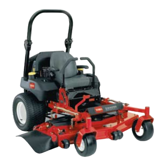
Toro 74274 Operator's Manual
With a 72in turbo force side discharge mower
Hide thumbs
Also See for 74274:
- Operator's manual (80 pages) ,
- Operator's manual (68 pages) ,
- Operator's manual (76 pages)

Related Manuals for Toro 74274


Summary of Contents for Toro 74274
-
Page 1: Side Discharge
Form No. 3358-682 Rev A Z595-D Z Master ® with a 72in TURBO FORCE Side Discharge ® Mower Model No. 74274—Serial No. 270000001 and Up G001093 Register at www.Toro.com. Original Instructions (EN) -
Page 2: Table Of Contents
You are responsible for operating the product properly and safely. Figure 2 You may contact Toro directly at www.Toro.com for 1. Safety alert symbol product and accessory information, help finding a dealer, or to register your product. - Page 3 Using the Rollover Protection System Adjusting the Control Handle Neutral (ROPS) ............16 Position............47 Think Safety First ..........17 Hydraulic System Maintenance ....... 48 Operating the Parking Brake ....... 18 Servicing the Hydraulic System ......48 Starting and Stopping the Engine ......18 Setting the Hydraulic Pump Neutral Operating the Power Take Off (PTO) ....
-
Page 4: Safety
Safety • Use extra care when handling diesel and other fuels. They are flammable and vapors are explosive. Improper use or maintenance by the operator or owner – Use only an approved container can result in injury. To reduce the potential for injury, –... -
Page 5: Slope Operation
• Be certain that the seat belt can be released quickly decals. in the event of an emergency. • Be aware there is no rollover protection when the • Use only Toro approved attachments. Warranty may roll bar is down. be voided if used with unapproved attachments. -
Page 6: Slope Chart
Slope Chart Align this edge with a vertical surface (Tree, Building, Fence post, pole, etc.) -
Page 7: Safety And Instructional Decals
Safety and Instructional Decals Safety decals and instructions are easily visible to the operator and are located near any area of potential danger. Replace any decal that is damaged or lost. 58-6520 1. Grease 1-403005 66-1340 1-523552 65-2690 1-643253 68-8340 98-4387 1. - Page 8 98-5954 103-1636 107-1860 105-7798 107-1613 107-1857 107-1861...
- Page 9 107-1864 107-2114 107-2449 107-2102 108-5955 107-2112 108-5957...
- Page 10 108-5981 110-0305 110-3851 1. Remove the ignition key and read the instructions before servicing or performing maintenance. 110-2067 110-3852 1. Remove the ignition key 2. Continuous tone signals and read the instructions the user that engine is before servicing or overheating.
- Page 11 Manufacturer’s Mark 1. Indicates the blade is identified as a part from the original 110–3842 machine manufacturer. 110–0806 112-8319 106-7492...
- Page 12 106-9989 107-9309 1. Warning—read the Operator’s Manual for information on charging the battery; contains lead; do not discard. 2. Read the Operator’s Manual. 112-2389 1. Push to engage 6. Engine—start 2. Engine—preheat 7. Fast 3. Read the Operator’s 8. Continuous variable Manual.
-
Page 13: Product Overview
110-0819 Product Overview G001314 Figure 4 1. Hour meter 6. Throttle control 2. Ignition switch 7. PTO Switch 3. Glow plug switch 8. Audible alarm 4. Glow plug light 9. Fuel selector valve G001047 5. Engine Temperature light Figure 3 1. -
Page 14: Operation
Audible Alarm Operation This machine has an audible alarm that alerts the user Note: Determine the left and right sides of the to turn off the engine or engine damage can occur from machine from the normal operating position. over heating. Refer to Servicing the Cooling System in Cooling System Maintenance , page 41. -
Page 15: Checking The Engine Oil Level
the filler neck. This space in the tank allows the fuel to expand. Do not fill the fuel tanks completely full. In certain conditions, fuel is extremely 3. Install fuel tank caps securely. Wipe up any fuel that flammable and highly explosive. A fire or may have spilled. -
Page 16: Using The Rollover Protection System (Rops)
There is no rollover protection when the roll bar is in the down position. • Lower the roll bar only when absolutely necessary. • Do not wear the seat belt when the roll bar is in the down position. • Drive slowly and carefully. •... -
Page 17: Think Safety First
Important: Always use the seat belt with the roll bar in the raised position. Operating on wet grass or steep slopes can cause sliding and loss of control. Wheels dropping over edges can cause rollovers, which may result in serious injury, death or drowning. -
Page 18: Operating The Parking Brake
This machine produces sound levels in excess of 85 dBA at the operators ear and can cause hearing loss through extended periods of exposure. Wear hearing protection when operating this machine. The use of protective equipment for eyes, ears, feet and head is recommended. -
Page 19: Starting The Engine In Cold Weather
G001063 Figure 12 1. Ignition switch 3. Run 2. Off 4. Start G000961 Figure 11 1. Hour meter 5. Engine Temperature light 2. Ignition switch 6. Throttle control 3. Glow plug switch 7. PTO Switch 4. Glow plug light 9. Turn the key to the start position and the glow plug indicator light will come back on. -
Page 20: Operating The Power Take Off (Pto)
Important: Use starting cycles of no more than 2. While seated in the seat, release the pressure on the 30 seconds per minute to avoid overheating the traction control levers and place in neutral. starter motor. 3. Place the throttle in the fast position. Note: Do not use fuel left over from the summer. -
Page 21: Driving Forward Or Backward
• The power take off (PTO) is disengaged. • The motion control levers are in the neutral locked Machine can spin very rapidly. Operator may position lose control of machine and cause personal The safety interlock system also is designed to stop the injury or damage to machine. -
Page 22: Stopping The Machine
Children or bystanders may be injured if they move or attempt to operate the tractor while it is unattended. Always remove the ignition key and set the parking brake when leaving the machine unattended, even if just for a few minutes. Adjusting the Height-of-Cut The height-of-cut is adjusted from 1-1/2 to 5 inch (38 to 127 mm) in 1/4 inch (6 mm) increments by... -
Page 23: Adjusting The Flow Baffle
2. Stop the engine, remove the key, and wait for all moving parts to stop before leaving the operating position. 3. After adjusting the height-of-cut, adjust the rollers by removing the flange nut, bushing, spacer, and bolt (Figure 17 , Figure 18 and Figure 19 ). Note: The two middle rollers will not have a spacer (Figure 18). -
Page 24: Positioning The Flow Baffle
• Lowers the engine power consumption. • Allows increased ground speed in heavy conditions. This is the full rear position. The suggested use for this • This position is similar to the benefits of the Toro position is a follows. SFS mower. -
Page 25: Unlatching The Seat
Pushing the Machine Important: To adjust, move the lever sideways to unlock seat (Figure 24). 1. Disengage the power take off (PTO) and turn the ignition key to off. Move the levers to neutral locked Slide the seat to the desired position and release lever position and apply parking brake. -
Page 26: Transporting Machines
Loading Machines Use extreme caution when loading units on trailers or Without the grass deflector, discharge cover, trucks. One full width ramp that is wide enough to or complete grass catcher assembly mounted extend beyond the rear tires is recommended instead of in place, you and others are exposed to blade individual ramps for each side of the unit (Figure 27). -
Page 27: Operating Tips
Mowing Direction Alternate mowing direction to keep the grass standing straight. This also helps disperse clippings which enhances decomposition and fertilization. Mow at Correct Intervals Normally, mow every four days. But remember, grass grows at different rates at different times. So to maintain the same cutting height, which is a good practice, mow more often in early spring. - Page 28 Check the cutter blades daily for sharpness, and for any wear or damage. File down any nicks and sharpen the blades as necessary. If a blade is damaged or worn, replace it immediately with a genuine TORO replacement blade.
-
Page 29: Maintenance
Maintenance Recommended Maintenance Schedule(s) Maintenance Service Maintenance Procedure Interval • Check the engine cooling system level. • Adjust the mower belt tension. After the first 8 hours • Check the hydraulic fluid. • Change the hydraulic filter and check hydraulic oil level. After the first 25 hours •... -
Page 30: Lubrication
If you leave the key in the ignition switch, someone could accidently start the engine and seriously injure you or other bystanders. Remove the key from the ignition before you do any maintenance. Lubrication Greasing and Lubrication Lubricate the machine when shown on the Check Service Reference Aid decal (Figure 28). -
Page 31: Engine Maintenance
Engine Maintenance Important: Make sure cutting unit spindles are full of grease weekly. 1. Disengage the PTO, move the motion control levers Servicing the Air Cleaner to the neutral locked position and set the parking brake. Note: Check the filters more frequently if operating conditions are extremely dusty or sandy. -
Page 32: Servicing The Engine Oil
G001049 G001048 Figure 31 Figure 32 1. Air filter body 3. Air cleaner cover 1. Air filter body 3. Air cleaner cover 2. Air filter 4. Latches 2. Air filter 4. Latches Installing the Air Filter Servicing the Engine Oil 1. -
Page 33: Changing The Engine Oil
Checking the Engine Oil Level Every 100 hours Service Interval: Before each use or daily 1. Start the engine and let it run for five minutes. This warms the oil so it drains better. Note: Check the oil when the engine is cold. 2. - Page 34 G001163 G001312 Figure 38 1. Engine oil 2. Funnel and hose Figure 36 1. Knob 2. Front engine panel Important: Add the oil very slowly and do not block the opening of the filler hole (Figure 39). If you add oil too fast or block the hole, the oil 2.
-
Page 35: Changing The Engine Oil Filter
Changing the Engine Oil Filter Service Interval: After the first 50 hours Every 200 hours 1. Place a drip pan beneath the oil drip tray to receive oil from the oil filter and oil passages in the engine. 2. Drain the oil from the engine; refer to Changing the Engine Oil. -
Page 36: Fuel System Maintenance
Fuel System Electrical System Maintenance Maintenance Servicing the Fuel Filters Servicing the Battery Replacing the Fuel Filter Warning Service Interval: Every 400 hours (or yearly, which ever CALIFORNIA comes first) (more often in dirty or Proposition 65 Warning dusty conditions). Battery posts, terminals, and related accessories contain lead and lead compounds, Ensure that an Authorized Service Dealer replaces the... -
Page 37: Installing The Battery
Incorrect battery cable routing could damage the machine and cables causing sparks. Sparks can cause the battery gasses to explode, resulting in personal injury. • Always Disconnect the negative (black) battery cable before disconnecting the positive (red) cable. • Always Reconnect the positive (red) battery cable before reconnecting the negative (black) cable. -
Page 38: Servicing The Fuses
Important: Always keep the battery fully charged (1.265 specific gravity). This is especially important to prevent battery damage when the temperature is below 32°F (0°C). 1. Make sure the filler caps are installed in battery. Charge battery for 10 to 15 minutes at 25 to 30 amps or 30 minutes at 10 amps. -
Page 39: Drive System Maintenance
Drive System Maintenance Adjusting the Tracking The machine has a knob for adjusting the tracking located under the seat. Important: Adjust the handle neutral and hydraulic pump neutral before adjusting the tracking. Refer to Adjusting the Handle Neutral in Controls System Maintenance , page 47 and Adjusting the Hydraulic Pump Neutral in Hydraulic System Maintenance , page 48. -
Page 40: Checking The Wheel Hub Slotted Nut
Checking the Wheel Hub 3. Remove the dust cap from caster and tighten lock nut (Figure 49). Slotted Nut 4. Tighten the locknut until the spring washers are flat Service Interval: Every 500 hours and then back off a 1/4 turn to properly set the pre-load on the bearings (Figure 49). -
Page 41: Cooling System Maintenance
Cooling System Maintenance Servicing the Cooling System Discharge of hot pressurized coolant or touching hot radiator and surrounding parts can cause severe burns. • Do not remove the radiator cap when the engine is hot. Always allow the engine to cool at least 15 minutes or until the radiator cap is cool enough to touch without burning your hand before removing the radiator cap. -
Page 42: Radiator Screen
1. Position the machine on a level surface, stop the engine, and set the parking brake. 2. Unlatch the seat and tilt the seat up. 3. With the engine cool, check the overflow bottle level. The fluid needs to be up to the bump on the outside of the overflow bottle (Figure 51). -
Page 43: Brake Maintenance
Brake Maintenance Belt Maintenance Inspecting the Belts Adjusting the Parking Brake Service Interval: Every 100 hours Service Interval: Every 25 hours Check the belts for squealing when the belt is rotating, Every 200 hours blades slipping when cutting grass, frayed belt edges, 1. -
Page 44: Adjusting The Mower Belt Tension
Adjusting the Mower Belt Tension Service Interval: After the first 8 hours Important: To ensure proper mower belt tension, which will result in a longer belt life, check the mower belt tension after the first 8 hours of use and 8 hours after each belt change. -
Page 45: Replacing The Pto Drive Belt
Replacing the PTO Drive Belt Service Interval: Every 50 hours 1. Disengage the PTO, move the motion control levers to the neutral locked position and set the parking brake. 2. Stop the engine, remove the key, and wait for all moving parts to stop before leaving the operating position. -
Page 46: Replacing And Tensioning The Alternator Belt
G001158 G001295 Figure 60 Figure 61 1. Pump drive belt 3. Spring loaded idler pulley 1. Oil cooler shield 3. Engine straps 2. Clutch 4. Spring 2. Bolts 5. Remove the 4 bolts holding the oil cooler and Replacing and Tensioning the position the oil cooler to the side (Figure 62). -
Page 47: Controls System Maintenance
Controls System 12. Install the oil cooler shield and engine straps to the rear frame with the 4 bolts previously removed Maintenance (Figure 61). 13. Install the engine straps to the side of the machine (Figure 61). Adjusting the Control Handle 14. -
Page 48: Hydraulic System Maintenance
Hydraulic System 9. Apply slight rearward pressure on the motion control lever, turn the head of the adjustment bolt Maintenance in the appropriate direction until the control lever is centered in the neutral lock position (Figure 65). Note: Keeping rearward pressure on the lever will Servicing the Hydraulic keep the pin at the end of the slot and allow the System... - Page 49 2. Stop the engine, remove the key, and wait for all moving parts to stop before leaving the operating position. Important: Do not substitute automotive oil filter or severe hydraulic system damage may result. 3. Place drain pan under filter, remove the old filter and wipe the filter adapter gasket surface clean (Figure 67).
-
Page 50: Setting The Hydraulic Pump Neutral Position
adapter, then tighten the filter an additional 1/2 turn After every 100 operating hours, check the hydraulic (Figure 69). hoses for leaks, loose fittings, kinked lines, loose mounting supports, wear, weather and chemical 10. Clean up any spilled fluid. deterioration. Make necessary repairs before operating. 11. - Page 51 Engine must be running so motion control adjustment can be performed. Contact with moving parts or hot surfaces may cause personal injury. Keep hands, feet, face, clothing and other body parts away from rotating parts, muffler and other hot surfaces. 1.
-
Page 52: Mower Deck Maintenance
Mower Deck Maintenance Leveling the Mower at Three Positions Important: There are only three measuring positions needed to level the mower. Setting Up the Machine 1. Position mower on a flat surface. 2. Disengage the PTO, move the motion control levers to the neutral locked position and set the parking brake. - Page 53 Adjusting the Front-to-Rear Mower Pitch 1. Position the right blade front-to-rear (Figure 74). 2. Measure the right blade at the A location, from a level surface to the cutting edge of the blade tip (Figure 74). G001042 Figure 72 1. Measure here from blade 2.
-
Page 54: Servicing The Cutting Blades
4. Crack forming wear or damage. File down any nicks and sharpen the blades as necessary. If a blade is damaged or worn, replace it immediately with a genuine Toro replacement Checking for Bent Blades blade. For convenient sharpening and replacement, you 1. -
Page 55: Removing The Blades
Blades must be replaced if a solid object is hit, if the blade is out of balance or is bent. To ensure optimum performance and continued safety conformance of G000277 the machine, use genuine TORO replacement blades. Figure 79 Replacement blades made by other manufacturers may 1. Blade 2. -
Page 56: Replacing The Grass Deflector
Installing the Blades Note: Make sure the L end of the spring is installed behind the deck edge before installing the bolt as 1. Install the blade onto the spindle shaft (Figure 80). shown in Figure 81. Important: The curved part of the blade must 3. -
Page 57: Cleaning
Cleaning Storage Cleaning and Storage Cleaning Under the Mower 1. Disengage the power take off (PTO), set the parking Service Interval: Before each use or daily brake, and turn the ignition key to Off. Remove the key. Remove the grass buildup under the mower daily. 2. - Page 58 D. Dispose of fuel properly. Recycle as per local codes. Important: Do not store stabilizer/conditioned fuel over 90 days. 13. Check and tighten all bolts, nuts, and screws. Repair or replace any part that is damaged. 14. Paint all scratched or bare metal surfaces. Paint is available from your Authorized Service Dealer.
-
Page 59: Troubleshooting
Troubleshooting Problem Possible Cause Corrective Action Starter does not crank 1. Blade control (PTO) is engaged. 1. Move blade contro (PTO) to disengaged. 2. Parking brake is not on. 2. Set the parking brake. 3. Operator is not seated. 3. Sit on the seat. 4. - Page 60 Problem Possible Cause Corrective Action Uneven cutting height. 1. Blade(s) not sharp. 1. Sharpen the blade(s). 2. Cutting blade(s) is/are bent. 2. Install new cutting blade(s). 3. Mower is not level. 3. Level mower from side-to-side and front-to-rear. 4. Underside of mower is dirty. 4.
-
Page 61: Schematics
Schematics Wire Diagram (Rev. A) - Page 62 Notes:...
- Page 63 You are responsible for presenting your equipment to an Authorized Service Dealer as soon as the problem exists. The warranty repairs should be completed in a reasonable amount of time, not to exceed 30 days. If you have a question regarding your warranty coverage, you should contact The Toro® Company at 1-952–948–4027 or call us toll free at the number listed in your Toro Warranty statement.
- Page 64 Countries Other than the United States or Canada Customers who have purchased Toro products exported from the United States or Canada should contact their Toro Distributor (Dealer) to obtain guarantee policies for your country, province, or state. If for any reason you are dissatised with your Distributor’s service or have difculty obtaining guarantee information, contact the Toro importer.
Need help?
Do you have a question about the 74274 and is the answer not in the manual?
Questions and answers