
Related Manuals for Toro 62925


Summary of Contents for Toro 62925
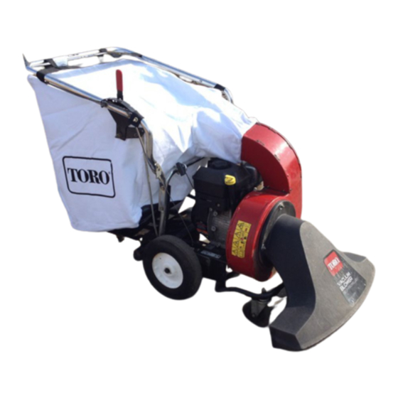
- Page 1 Form No. 3325-759 5.5 HP. Vacuum/Blower Model No. 62925—210000001 and Up Operator’s Manual International English (GB)
-
Page 2: Table Of Contents
Thank you for purchasing a Toro product. conforme à la norme NMB-002 du Canada. All of us at Toro want you to be completely satisfied with The enclosed Engine Owner’s Manual is supplied for your new product, so feel free to contact your local information regarding The U.S. -
Page 3: Safety
Caution signals a hazard that may cause minor or Be alert and turn the machine off if children enter the moderate injury if the recommended precautions are not area. followed. Use extra care when approaching blind corners, Two other words are also used to highlight information. shrubs, trees, or other objects that may obscure vision. -
Page 4: Sound Pressure Level
– before checking, cleaning, or working on the machine To ensure the best performance and safety, purchase only genuine Toro replacement parts and accessories. – before changing from vacuum to blower or blower to vacuum Maintain or replace safety and instruction decals when necessary. -
Page 5: Safety And Instruction Decals
Safety and Instruction Decals Safety decals and instructions are easily visible to the operator and are located near any area of potential danger. Replace any decal that is damaged or lost. 105-4062 1. Warning—read the 2. Thrown object hazard—keep 3. Warning—stop the engine 4. -
Page 6: Assembly
Assembly Loose Parts Note: Use the chart below to verify all parts have been shipped with unit. Description Qty. Upper handle assembly Bag support Install upper handle Install upper handle Hex head bolt, 5/16 x 1-1/2 in. Locknut, 5/15 in. Hex head bolt, 1/4 x 1-13/4 in. -
Page 7: Installing The Discharge Chute And Bag
2. Secure the bag support to the inside of the lower handle while mounting the handle (Fig. 2). 3. Secure starter rope guide to the lower handle with a bolt and locknut (Fig. 3). 1823 Figure 5 1. Height control rod 3. -
Page 8: Installing The Snout
2. Position the bag onto the handle, hooking the Before Operating grommets over the pins and the bag strap over the handle (Fig. 8). Before operating, check the fuel and oil level, and remove debris from the machine. Also, ensure that the area is clear of people and debris. -
Page 9: Checking The Oil Level
Using Stabilizer/Conditioner Use a fuel stabilizer/conditioner in the traction unit to provide the following benefits: Keeps gasoline fresh during storage of 90 days or less. For longer storage it is recommended that the fuel tank be drained. Cleans the engine while it runs Figure 10 Eliminates gum-like varnish buildup in the fuel system, which causes hard starting... -
Page 10: Starting The Engine
Starting the Engine Warning 1. Move the choke lever (located on the left side of the engine) to the Choke position (Fig. 11). The impeller continues to rotate for a few seconds after the engine is stopped, and can cause serious personal injury. -
Page 11: Driving The Machine Forward
Check the debris bag frequently. If it is damaged, install a new Toro replacement bag. Using the Bag Vent 1819 The bag has a zippered vent (Fig. 14). When vacuuming... - Page 12 3. Remove the bag neck from blower discharge chute 11. Reseat the housing, nesting the lower blower housing (Fig. 15). (You may remove the entire bag if desired.) mounting bracket onto the front edge of the engine base (Fig. 17). 4.
-
Page 13: Maintenance
Maintenance Recommended Maintenance Schedule Maintenance Service Maintenance Procedure Interval Check engine oil level Each use Check for loose fasteners Remove all dirt and debris from around the muffler Clean the foam pre-filter and the paper air filter 25 hours Grease the rear idler assembly 1, 2 50 hours or yearly Change engine oil... -
Page 14: Changing Engine Oil
Oil Type: SAE 30 or 10W-30 detergent oil (API service SG, SH, SJ, or higher) Crankcase Capacity: 20 oz. (0.6 l) Changing the Oil 1. Start the engine and let it run for five minutes. This warms the oil so it drains better. 1. -
Page 15: Lubricating The Machine
Emptying the Fuel Tank Important Do not overfill the crankcase with oil because the engine may be damaged. 1. Stop the engine and wait for it to cool. 8. Replace and tighten the dipstick. Important Drain gasoline from a cold engine only. Lubricating the Machine 2. -
Page 16: Servicing The Traction Drive
3. Bend the side electrode (Fig. 23) if the gap is not correct. 0.030 in. (0.76 mm) m–3215 Figure 23 1. Center electrode insulator 3. Air gap (not to scale) 2. Side electrode 1829 Figure 24 1. Lower nut 3. Bracket Installing the Spark Plug 2. - Page 17 1826 Figure 25 1. Nut 2. Pulleys 3. Tighten the nut just enough so the belt does not slip; do not over-tighten it. Note: When you can no longer adjust a pulley, use the other pulley. When the adjustment is used up on both pulleys, replace the belt.
-
Page 18: Storage
1827 Figure 27 1. Belt around housing 1826 Figure 29 11. Insert the belt over the pulley and down through the 1. Cotter pin 4. Belt opening (Fig. 28). 2. Set screws 5. Sprockets 3. Shaft 15. Install the belt around the drive shaft pulley (Fig. 29). Important The belt must be installed as shown in Figure 29 or the traction drive will run backward. - Page 19 7. With the spark plug removed from the engine, pour 2 tablespoons (10 ml) of engine oil into the spark plug hole. 8. Place rags over the spark plug hole to catch any oil spray, then use the starter rope to crank the engine and distribute the oil inside the cylinder.
Need help?
Do you have a question about the 62925 and is the answer not in the manual?
Questions and answers