
Related Manuals for minkaAire VOLTERRA II


Summary of Contents for minkaAire VOLTERRA II
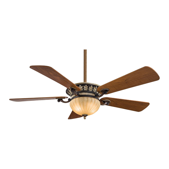
- Page 1 VOLTERRA II © 2002 Minka Lighting, Inc. INSTRUCTION MANUAL WARRANTY CERTIFICATE...
- Page 2 This product is protected by United States Federal and/or State Law, including Patent, Trademark and/or Copyright laws. Manual design and all elements of manual design are protected by U.S. Federal and/or State Law, including Patent, Trademark and/or Copyright laws.
- Page 3 Minka-Aire warrants to the original owner that this fan will be free from defects in material and workmanship for one year from the date of purchase, excluding the motor. Minka-Aire warrants to the original owner that the motor in this fan shall be free from defects in material and workmanship for as long as the original purchaser owns the fan, and it remains in the original installation.
- Page 4 This warranty shall not apply to fans which have been damaged in any way, including improper installation, damage as a result of the removal of the fan from the origial installation, or damage in shipping. This warranty shall not apply to fans which have been subjected to use for which the fan was not designed.
-
Page 5: Table Of Contents
CONTENTS SAFETY RULES..................FINISHING THE INSTALLATION............PACKAGE CONTENTS..............BLADE INSTALLATION................INSTALLING THE FAN..............INSTALLING THE LIGHT ..............ASSEMBLING THE FAN..............OPERATING YOUR WALL TRANSMITTER........HANGING THE FAN................. CARE OF YOUR FAN................ELECTRICAL CONNECTIONS............TROUBLESHOOTING................INSTALLING THE WALL TRANSMITTER......... SPECIFICATIONS..................LISTED E75795 1151 W. -
Page 6: Safety Rules
SAFETY RULES 1. Before you begin installing the fan, shut the power off at the circuit breaker or the fuse box. 2. Be Cautious! Read all instructions and safety information before installing your new fan. Review the accompanying assembly diagrams. 3. - Page 7 ATTENTION: ATTENTION: The Energy Policy Act of 2005 requires this fan to be equipped with a 190 watt limiting device. If lamping exceeds 190 watts, the ceiling fan's light kit will shut off automatically. NOTE: The important safeguards and instructions appearing in this manual are not meant to cover all possible conditions and situations that may occur.
-
Page 8: Package Contents
PACKAGE CONTENTS Unpack your fan and check the contents. 14a.Wall Transmitter Incl. 2 Mounting You should have the following items: Screws and 3 Wire Nuts 1. Fan blades (5 ) 14b.Wall Plate w/2 Mounting screws 2a. Hanger bracket plate 15. 50W Halogen bulb (2) 2b. -
Page 9: Installing The Fan
INSTALLING THE FAN Tools Required: Phillips screw driver; slotted screw driver; pliers; wire cutters; electrical tape. PARALLEL WOOD BRACE CEILING MOUNTING OPTIONS (MIN. 2" THICK) JOIST CROSS BRACE OUTLET If there isn¡ t an existing mounting box, then read the following instructions. Shut the power off at the circuit breaker or fuse box. -
Page 10: Assembling The Fan
ASSEMBLING THE FAN Your fan is packed with the motor and Upper Housing unassembled, proceed the following steps for fan assembly: THUMB SCREWS RUBBER WASHERS THUMB SCREWS ATTENTION: The Energy Policy Act of 2005 requires this fan to be equipped RUBBER WASHERS with a 190 watt limiting device. -
Page 11: Hanging The Fan
HANGING THE FAN Step 3. Secure hanger bracket to hanger bracket plate using the two WARNING: All of the parts, hardware and components such as the hex nuts and washers provided, make sure nuts are securely tighten. hanger bracket and hanger ball have been provided for your safety and (Fig. - Page 12 NOTE: DO NOT INSTALL THE COUPLING COVER OR DECORATIVE SCROLL IF YOU PLAN TO USE THE MINIMUM LENGTH DOWNROD. Step 8. Now lift motor assembly into position and place hanger ball into hanger bracket. Rotate until the check groove has dropped into the registration slot and seats firmly.
- Page 13 DOWNROD COUPLING CANOPY *OMIT COUPLING COVER WHEN THE MINIMUM-LENGTH DOWNROD CANOPY COVER REGISTRATION SLOT SET SCREWS Fig. 14 HITCH PIN LOCK PIN Fig. 13...
-
Page 14: Electrical Connections
ELECTRICAL CONNECTIONS WARNING: To avoid possible electrical shock be sure electricity is Step 2. Motor to Receiver Electrical Connections: Connect the WHITE turned off at the main fuse or breaker box before wiring. wire from the fan to the WHITE wire marked "TO MOTOR N" from the Receiver. - Page 15 Step 3. Receiver to House Supply Wires Electrical Connections: Connect the WHITE wire (Neutral) from the outlet box to the WHITE wire marked "AC in N" from the receiver. Connect the BLACK wire (Hot) from the outlet box to the BLACK wire marked "AC in L" from the receiver.
- Page 16 Fig. 17 Fig. 18...
-
Page 17: Installing The Wall Transmitter
INSTALLING THE WALL TRANSMITTER WARNING! HOOK UP "IN SERIES" ONLY. DO NOT CONNECT NEUTRAL SUPPLY WIRE OF ELECTRIC CIRCUIT TO THE TRANSMITTER WALL SWITCH, DAMAGE TO THE TRANSMITTER WALL SWITCH AND POSSIBLE FIRE COULD OCCUR. Step 1. Remove the existing wall plate and switch from the wall outlet box. Step 2. -
Page 18: Finishing The Installation
FINISHING THE INSTALLATION Step 1. Tuck connections neatly into ceiling outlet box. Step 2. Slide the canopy up to ceiling and over the two screws on hanger bracket. Rotate canopy clockwise, next, while holding the canopy with one hand, slide the canopy cover over the screws and rotate clockwise until tight. -
Page 19: Blade Installation
BLADE INSTALLATION THE FOLLOWING OPERATION MUST BE ACCOMPLISHED BEFORE INSTALLING THE LIGHT KIT. Step1. Attach the fan blade to the blade holder using the screws and fiber washers provided. Tighten screws securely. Repeat process for remaining blades.(Fig. 21) Step2. Rotate motor until holes become visible through the light plate access window. -
Page 20: Installing The Light
INSTALLING THE LIGHT KIT WARNING: Shut of the power supply before removing or replacing lamp. In handling of halogen bulb, care should be taken not to touch it with your bare hands. Oil residue will shorten the life of the halogen bulb. If you accidentally come into contact, wipe thoroughly with a clean, lint-free, cotton cloth. - Page 21 4. Remove the metal plate, glass cap and finial from the light kit. Raise the glass shade up against the light kit, Place the metal plate with rubber on the top over the stem and turn it clockwise until it locks up against the glass shade.
- Page 22 OPERATING THE REMOTE CONTROL/WALL CONTROL Remote Control only: Install a A23 12 volt battery (included). To prevent damage to transmitter remove the battery if not used for long periods of time. Restore Power to Ceiling Fan. instructions apply to ceiling fans that feature a DOWN D.
- Page 23 Speed settings for warm or cold weather depend on factors such as room size, ceiling height and number of fans. NOTE: Wait for fan to stop before changing the setting of the slide switch. Warm Weather (forward) A DOWNWARD airflow creates a cooling effect as shown in Figure 24.
-
Page 24: Care Of Your Fan
CARE OF YOUR FAN Here are some suggestions to help maintain your fan. 4. Use a lint free lightly damp cloth or duster to remove dust from the blades. 5. There is no need to oil your fan. The motor has permanently lubricated 1. -
Page 25: Troubleshooting
TROUBLESHOOTING SYMPTOM SYMPTOM Fan will not start Fan Sounds Noisy SOLUTION SOLUTION Check to make sure the wall switch is turned on. Allow a 24-hour "break in" period. Most noises associated with a new fan will go away during this time. Check circuit fuses or breakers. - Page 26 SYMPTOM SYMPTOM Fan Wobble Lights shut off and will not come back on. SOLUTION SOLUTION NOTE: All blade sets are grouped by weight. Because wood and This unit is equipped with a wattage limiting device. Lamping in plastic blades vary in density, the fan may wobble even though excess of 190 watts will disable your ceiling fan’s light kit.
- Page 27 SYMPTOM Frequency Interference SOLUTION Turn the power off to your ceiling fan. Please use a small size tool to change the frequency settings on the control system. Return power to the unit. Note: After the AC power is on, do not press any other button on the transmitter before pressing the "Stop" button, doing so will cause the procedure to fail.
-
Page 28: Specifications
SPECIFICATIONS Fan Size Speed Volts Amps Watts RPM CFM N.W. G.W. C.F. These are typical readings. Your actual fan may vary. They do not include amps and wattage used by the 0.38 3800 23.8 20.52 5.07' light(s). 68" Medium 0.54 4900 0.61 5850...
Need help?
Do you have a question about the VOLTERRA II and is the answer not in the manual?
Questions and answers