
Related Manuals for Toro 38590


Summary of Contents for Toro 38590
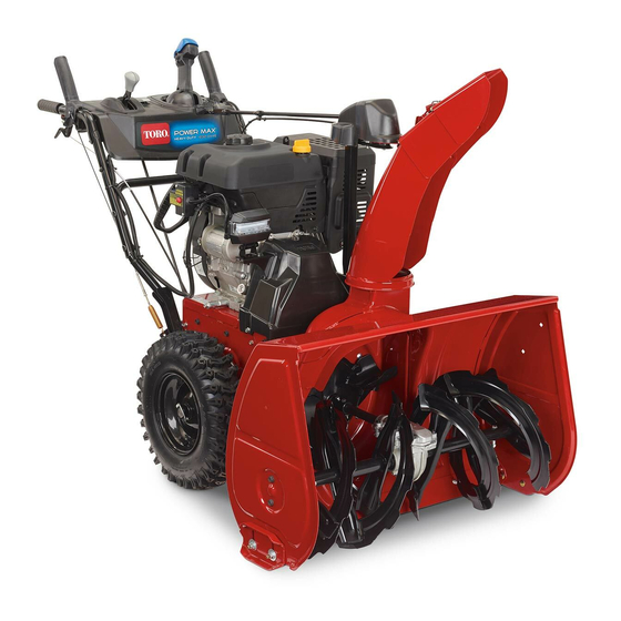
- Page 1 FORM NO. 3321–693 1232 Power Shift Snowthrower Model No. 38590–9900001 & Up Operator’s Manual...
- Page 2 WARNING: The engine exhaust from this product contains chemicals known to the State of California to cause cancer, birth defects, or other reproductive harm.
- Page 3 3. Flange head capscrew 1. Auger housing 4. Idler pulley assembly 2. Engine frame 5. Mounting screws (2) 3. Impeller pulley 1. Upper belt cover 3. Flange head capscrew 2. Cable cover The Toro Company – 1998 All Rights Reserved Printed in USA...
-
Page 4: Table Of Contents
1. Discharge chute 3. Chute retainer plate 2. Plastic chute retainer 4. Chute ring 1. Shift rod 5. Locknut 2. Ball joint 6. Jam nut 3. Shift bracket 7. Gear shift lever 4. Transmission lever 8. Power Shift slot 1. Gear bracket 3. - Page 5 1. Scraper 3. Auger blades 1. Pipe plug 2. Carriage bolt 2238 1. Flange bolts 4. Locknut 1. Dipstick 3. Fuel tank cap 2. Skid 5. Sideplate 2. Filler hole 3. Flat washers m-4058...
- Page 6 2236 1. Fuel shut-off valve 3. Fuel line 2. Hose clamp m-4059 1. Auger/impeller control 3. Speed shift control 2. Traction drive control 4. Discharge chute control 1. Deflector handle 2. Discharge chute m-4034 1. Throttle 3. Primer 2. Choke 4.
- Page 7 2238 1. Heater box 3. Hex head screw (2) 2. Phillips screw (2) 1. Axle pin 3. Outer axle hole and wheel 2. Inner axle hole m-4060...
- Page 8 2163 1. Release tab – lock spring 4. Lock spring 2. Right hand shaft groove 5. Coupling (unlock position) 6. Differential 1. Move wheels to rear 3. Push lock spring up to 3. Left hand shaft groove disengage from shaft (lock position) 2.
-
Page 9: Jam Nut
1. Auger/impeller cable 3. Mounting bracket (outer cable) 4. Jam nut 2. Traction cable (inner 1. Drain cap cable) 1/8” min. (3 mm) 1. Feeler gauge 2. Center of spring 1. Impeller idler arm 2. Brake arm... - Page 10 1. Transmission 2. Transmission frame 1. Idler pulley assembly 5. Auger/impeller belt 2. Flange head capscrews 6. Traction belt 7. Middle pulley section 3. Capscrew & lockwasher 8. Idler pulley (2) 4. Half sheave 1. 1/8” – 3/8” deflection 1. Flange head capscrews viii...
- Page 11 0.30” (0.76 mm) 2238 1. Spark plug wire...
-
Page 12: Introduction
While Operating ..... All of us at Toro want you to be completely satisfied Maintaining Snowthrower ... . . -
Page 13: Auger/Impeller Control
Before Operating DANGER, WARNING and CAUTION are signal words used to identify the level of hazard. However, regardless of the hazard, be extremely careful. Read and understand the contents of this manual before operating the snowthrower. Become DANGER signals an extreme hazard that will cause familiar with all controls and know how to stop serious injury or death if the recommended the engine quickly. -
Page 14: Fuel Tank Cap
11. Fill fuel tank with gasoline before starting the 14. Before leaving the operator’s position (behind engine. Avoid spilling any gasoline. Because handles), remove key from switch. gasoline is highly flammable, handle it carefully. 15. Allow engine to warm up outdoors before DO NOT SMOKE WHILE HANDLING clearing snow. -
Page 15: Maintaining Snowthrower
TORO replacement parts and are tight. accessories to keep the TORO all TORO. NEVER USE “WILL FIT” REPLACEMENT 28. Maintain or replace safety and instruction labels, PARTS AND ACCESSORIES. - Page 16 BEFORE OPERATING Read and understand the contents of this manual CAUTION: IMPROPER USE MAY RESULT before operating the snowthrower. Become IN LOSS OF FINGERS, HANDS OR FEET. familiar with all controls and know how to stop the engine quickly. HIGH SPEED IMPELLER WITHIN 2 INCHES OF OPENING OPERATOR’S...
-
Page 17: Safety Decals And Instructions
Safety decals and instructions are easily visible to the operator and are located near any area of potential danger. Replace any decal that is damaged or lost. Decals with Tecumseh part numbers must be obtained from Tecumseh Products Company. Decals with Toro part numbers must be obtained from The Toro Company. ON ENGINE (Tecumseh Part No. -
Page 18: Shift Rod
Loose Parts Part Flange head capscrew — 5/16-18 x 3/4” lg. Lower belt cover Mount Auger/impeller Housing page 8 Mount Auger/impeller Housing, page 8 Flange head capscrew — 1/4-20 x 1/2” lg. Cable cover Shift rod Install Shift Rod, page 8 Install Shift Rod page 8 Locknut—3/8-16 Discharge chute... -
Page 19: Transmission Lever
Assembly Note: Shift rod to be positioned with bend rearward. Note: Determine left and right sides of Insert bottom ball joint stud through right side of snowthrower by standing in the normal transmission lever and secure with 3/8-16 operating position. locknut. -
Page 20: Mounting Flange
Install Chute Control Gear Install (2) flange bolts through front slots in skids and thru sideplates. Install flat washers and (Fig. 7) locknuts on inside of sideplates. Do not tighten bolts. Insert the 5/16-18 x 1” lg. carriage bolt into gear bracket mounting hole. -
Page 21: Filler Hole
Before Starting Fill Fuel Tank With Gasoline Fill Crankcase With Oil The engine is shipped from the factory without oil in POTENTIAL HAZARD the crankcase. Therefore, before starting the engine, In certain conditions gasoline is extremely oil must be added to the crankcase. flammable and highly explosive. -
Page 22: Traction Drive Control
Toro also recommends that Toro handle grip. To disengage, release lever. Stabilizer/Conditioner be used regularly in all Toro Traction Drive Control (Fig. 13)—To engage gasoline powered products during operation and traction (wheel drive) or activate power shift system, storage seasons. -
Page 23: Fuel Shut-Off Valve
Primer (Fig. 14)—Press primer to pump a small Open fuel shut-off valve below fuel tank amount of gasoline into engine for improved cold (Fig. 15). weather starting. Move choke to ON choke position (Fig. 14). Fuel Shut-Off Valve (Fig. 15)—Valve is located Insert ignition key (Fig. -
Page 24: Power Shift Operation
Note: Pulling of recoil starter rope produces a Note: If wheels do not move in desired loud, clattering sound. This is not direction when power shifting, repeat harmful to the engine or the starter. procedure. Stopping Free Wheeling Or Self-propelled Drive Release traction and auger/impeller drive control levers (Fig. -
Page 25: Operating Tips
Unlock position — Coupling lock spring in right 11. In wet or slushy conditions, clogging of the hand shaft groove (Fig. 23). discharge chute will be reduced by maintaining maximum engine speed and by not overloading the engine. Operating Tips When snowthrower is not being used, close fuel shut-off valve and remove key from the switch. -
Page 26: Adjusting Skids (Fig. 9)
Loosen the (4) flange bolts securing both skids Support the scraper to be 1/8 inch above a level to the auger side plates. surface if the snowthrower is to be used on smooth pavement. Next, loosen the carriage bolts securing the scraper to the auger housing. -
Page 27: Draining Gasoline
Draining Gasoline engine just before changing oil because warm oil flows better and carries more contaminants than cold oil. Close fuel shut-off valve located under fuel tank (Fig. 15). Pull wire off spark plug and make sure wire does not contact plug accidentally. Clean area around oil drain cap. -
Page 28: Adjusting Traction Drive Belt (Fig. 27)
INSTALLED, AN ADJUSTMENT IS REQUIRED. USE ONLY GENUINE TORO REPLACEMENT PARTS. POTENTIAL HAZARD Pull wire off spark plug and make sure wire does Improper adjustment may cause injury if not contact plug accidentally. auger/impeller turns when disengaged. WHAT CAN HAPPEN... -
Page 29: Replacing Drive Belts (Fig. 29)
Check tension of belt by operating machine. Note: Make sure idler pulleys are aligned Machine should begin to move forward when with belts when reinstalling idler traction lever is depressed approximately pulley assembly. halfway down toward handle grip. Turn engine 10. -
Page 30: Replacing Spark Plug
Chain adjustment will affect gearshift lever alignment. If gear shift lever is not aligned with Add Toro Stabilizer/Conditioner to the fuel tank Power Shift slot in control panel (Fig. 5, inset), (one ounce per gallon of fuel). shift rod length must be adjusted as follows: Run engine for ten minutes to distribute A. - Page 31 NEVER STORE SNOWTHROWER IN HOUSE (LIVING Clean the snowthrower. Touch up chipped AREA) OR BASEMENT WHERE surfaces with paint. Toro Re-Kote paint is IGNITION SOURCES MAY BE PRESENT available from an Authorized TORO Service SUCH AS HOT WATER AND SPACE Dealer.
-
Page 32: Warranty
Distributor (Dealer) to obtain guarantee policies for your country, province, or state. If for any reason you are dissatisfied with your Distributor’s service or have difficulty obtaining guarantee information, contact the TORO importer. If all other rem- edies fail, you may contact us at The Toro Company.
Need help?
Do you have a question about the 38590 and is the answer not in the manual?
Questions and answers