
Subscribe to Our Youtube Channel
Related Manuals for Golden Buzzaround XL


Summary of Contents for Golden Buzzaround XL
- Page 1 Buzzaround XL Service Guide Model GB117 Model GB147 This Service Guide contains: Troubleshooting Replacement Instructions Multi-meter Instructions...
- Page 2 Buzzaround XL_SG_REVA...
-
Page 3: Table Of Contents
Buzzaround XL_SG_REVA Table of Contents Nomenclature and Contact Information.......................3 ABOUT THE BUZZAROUND XL SERVICE GUIDE................4 Buzzaround XL Components........................4-9 Wiring Diagram............................10 SCENARIO 1: Turn the key to the on position and no power..............11 SCENARIO 2: Batteries will not charge....................12 BEEP CODES............................13-18 BEEP CODE #1 –... -
Page 4: Nomenclature And Contact Information
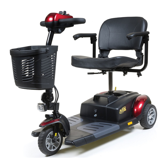
11 - Tiller 12 - Front Basket 13 - Seat Post 14 - Bolt, Arc Washer, and Nut 15 - Lockup Handle Figure 1. Buzzaround XL (Model GB117) Contact Information Golden Technologies 401 Bridge Street Old Forge, PA 18518 Toll-free: 800-624-6374... -
Page 5: About The Buzzaround Xl Service Guide
The Buzzaround XL is a battery-operated scooter with a controller that monitors the system and beeps when it detects a fault in the system. The Buzzaround XL was designed to operate within a range of between 18 - 24 volts (V) of direct current (DC). - Page 6 Buzzaround XL_SG_REVA Component: Circuit Breaker - #1 Location: Mounted on the Battery Pack. See figure 2. Function: Protects battery circuit from current overload. When the current draw exceeds the breaker rating, the circuit breaker will open. Connections: The circuit breaker is connected to the positive (+) terminal on one battery and the negative (-) terminal on the other.
- Page 7 Buzzaround XL_SG_REVA Figure 5. Controller Component: Power Harness - #5 Location: Mounted to the front frame – located under the battery pack. See #5 on figure 4. Function: Connects the battery pack to the controller. Connections: Connects to the battery pack to the controller (inhibit), (Bat -), (Bat +) connections. Refer to figure 11 on page 10.
- Page 8 Buzzaround XL_SG_REVA Component: Front Intermediate Harness - #8 Location: Mounted on the front frame. See figure 6. Function: Provides connectivity between the motor/brake and the controller. Connections: Connected to the rear intermediate connector (9) and the controller (6). Refer to figure 11 on page 10. Failure Signs: Scooter will run slowly or not at all.
- Page 9 Buzzaround XL_SG_REVA Component: Speed Pot (Potentiometer) - #12 Location: Mounted on the control panel. See #1 on figure 9. Function: The speed pot uses variable resistance to control the speed of the scooter. Connections: Connected to the main harness through the control panel harness. Failure Signs: Beep Code #7 Tests: Call Tech Support Expected readings: Depends on speed pot position.
- Page 10 Buzzaround XL_SG_REVA Component: Off-Board Charger Location: Stored inside a pouch on the seatback. Function: Recharges batteries. Connections: Connects to the charger port on the battery pack or the charger port on the tiller. The tiller port is connected to the batteries through the main harness.
-
Page 11: Wiring Diagram
Buzzaround XL_SG_REVA 30 AMP Circuit Breaker (1) Dynamic R-Series Controller (6) Battery Harness (4) Power Harness (5) Main Harness (7) Rear Intermediate Connector (9) Front Intermediate Harness (8) Brake (11) Motor / Brake Assembly (10) Figure 11. Buzzaround XL Wiring Diagram... -
Page 12: Scenario 1: Turn The Key To The On Position And No Power
Buzzaround XL_SG_REVA SCENARIO 1: TURN THE KEY TO THE ON POSITION AND NO POWER Put the key into the key switch and turn to the on position. There is no power to the control panel. The horn does not work and the battery condition meter does not work. -
Page 13: Scenario 2: Batteries Will Not Charge
Buzzaround XL_SG_REVA SCENARIO 2: BATTERIES WILL NOT CHARGE Most battery chargers need to “see” at least 16VDC at the charger port. Otherwise, they may not send a charging current to the batteries. This test will ensure that the battery voltage is making it to the charger port. You will need to check battery voltage and wiring harness continuity inside the battery pack. -
Page 14: Beep Codes
Buzzaround XL_SG_REVA BEEP CODES The controller uses audible beeps to indicate the status of the system. When the controller notices that there is a malfunction in the system, it will beep a code when the power is on. For example, when it beeps five times and stops that indicates beep code #5 –... -
Page 15: Beep Code #5 - Brake Fault
Buzzaround XL_SG_REVA Check for Continuity on the Front Intermediate Harness. 5. Remove the two gray floor panels by pushing them up from the underside of the scooter frame. 6. Remove the four screws fastening the floor shroud. 7. Disconnect the front intermediate harness (8) from the controller. Refer to figure 11 on page 10. 8. -
Page 16: Beep Code #6 - Paddle Fault (Out Of Neutral)
Buzzaround XL_SG_REVA Check for Continuity on the Front Intermediate Harness. 10. Separate the front and rear halves of the scooter. 11. Measure resistance from the connector (J3) pin 1 an pin 2 to the two middle pins on the connector of the front intermediate harness (8). -
Page 17: Beep Code #7 - Paddle Fault/Speed Control Fault (Voltage Error)
Buzzaround XL_SG_REVA BEEP CODE #7 - THROTTLE POT/SPEED CONTROL FAULT This Beep Code occurs because there is a fault with the throttle pot, speed pot, or the associated wiring. Check Throttle Pot Resistance at Controller. 1. Remove the seat. MEASURE RESISTANCE 2. -
Page 18: Beep Code #8 - Motor Voltage Fault (Open/Shorted)
Buzzaround XL_SG_REVA 13. Insert the multimeter probes into the throttle pot connector (14) at the orange wire and the white wire. See figure 26. Note the resistance reading. Insert the multimeter probes into the throttle pot connector (14) at the yellow wire and the white wire. -
Page 19: Beep Code #9 - Controller Fault
Buzzaround XL_SG_REVA Check Motor Resistance at Motor. 11. Measure resistance across the two outside pins on connector (9) that have the thick black wire and the thick red wire. (Internal resistance of the motor). See figure 29. • 0.8 ohms – 1.5 ohms? – Replace the controller. •... -
Page 20: Buzzaround Xl Replacement Instructions
Buzzaround XL_SG_REVA BUZZAROUND XL REPLACEMENT INSTRUCTIONS DRIVEWHEEL REPLACEMENT Tools needed: 13mm socket, frame blocks. 1. Place the freewheel lever into the engaged position. 2. Remove the key from the key switch. 3. Place the rear of the scooter onto blocks. -
Page 21: Battery
Buzzaround XL_SG_REVA BATTERY REPLACEMENT Tools needed: Phillips screwdriver, 8mm wrench 1. Place the freewheel lever in the engaged position. 2. Remove the key from the key switch. 3. Remove the seat. 4. Remove the battery pack. 5. Position the battery pack so that the screw heads are facing up. -
Page 22: Circuit Breaker
Buzzaround XL_SG_REVA CIRCUIT BREAKER REPLACEMENT Tools needed: Phillips screwdriver, 17mm socket 1. Place the freewheel lever in the engaged position. 2. Remove the key from the key switch. 3. Remove battery pack. 4. Remove the (9) screws that fasten the battery pack together. 5. -
Page 23: Main Harness
Buzzaround XL_SG_REVA CONTROL PANEL REPLACEMENT Tools needed: Phillips screwdriver and slotted screwdriver 1. Engage the park brake. 2. Remove the key from the key switch. 3. Remove the control panel shroud. See figure 36 . 4. Remove the (4) screws that fastens the control panel halves together See figure 37. -
Page 24: Motor/Brake
Buzzaround XL_SG_REVA MOTOR/BRAKE ASSEMBLY REPLACEMENT Tools needed: Phillips screwdriver, 5mm Allen wrench, cutters 1. Place the freewheel lever in the engaged position. 2. Remove the key from the key switch. Brake 3. Remove the seat. 4. Remove the battery pack. 5. -
Page 25: Rear Intermediate Connector
Buzzaround XL_SG_REVA At this time the entire harness can be removed by simply disconnecting the red and black motor wires and the 2-pin red/black connector from the controller. At this time to replace only the connector or harness separately, continue to step 10. 10. -
Page 26: Power Harness
Buzzaround XL_SG_REVA POWER HARNESS REPLACEMENT Tools needed: Phillips screwdriver, 7mm wrench Figure 42. Connector (Top View) 1. Place the freewheel lever in the engaged position. 2. Remove the key from the key switch. 3. Remove the seat. 4. Remove the battery pack. 5. -
Page 27: Appendix A - How To Use A Voltmeter
Buzzaround XL_SG_REVA APPENDIX A - HOW TO USE A VOLTMETER Step 1 Plug the probes into the meter. Red goes to the positive (+) and black to the negative (-). Step 2 Turn the selector dial or switch to the type of measurement you want. To measure direct current - a battery, for example - use DCV. -
Page 28: Appendix B - How To Use An Ohm Meter
Buzzaround XL_SG_REVA APPENDIX B - HOW TO USE AN OHM METER Ohm’s law breaks down into the basic equation: Voltage = Current x Resistance. Current is generally measured in amps, and resistance in ohms. Testing the resistance on an electrical circuit in your home or car can help you diagnose problems with that circuit. - Page 29 Buzzaround XL_SG_REVA...
- Page 30 Buzzaround XL_SG_REVA Model GB117S Model GB147S Golden Technologies 401 Bridge Street Old Forge, PA 18518 www.goldentech.com BUZZAROUND XL_SERVMAN_REVA_110915...
Need help?
Do you have a question about the Buzzaround XL and is the answer not in the manual?
Questions and answers