Advertisement
Advertisement

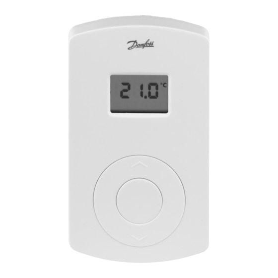
Related Manuals for Danfoss 088U0215


Summary of Contents for Danfoss 088U0215
- Page 1 088U0215 Instruction CF-RF Room Thermostat with Infrared Floor Sensor...
- Page 2 Instruction CF-RF Room Thermostat with Infrared Floor Sensor Danfoss Heating Solutions VIUHR402 © Danfoss 05/2011...
-
Page 3: Table Of Contents
8. Troubleshooting ........12 Figures and illustrations ......14 © Danfoss 05/2011 VIUHR402... -
Page 4: Functional Overview
Back plate Back plate lock/unlock (turn 90°) Screw hole for wall mounting Battery placement Screw and wall plug Note: To activate batteries please remove enclosed strips from batteries. Danfoss Heating Solutions VIUHR402 © Danfoss 05/2011... -
Page 5: Installation
Room thermostat installation status • Satisfactory: LED goes OFF. • Not satisfactory: LED flashes 5 times. Note: A room thermostat can be assigned to several outputs if needed by repeating the installation process. © Danfoss 05/2011 VIUHR402 Danfoss Heating Solutions... -
Page 6: Temperature Settings
3. Press the button shortly and repeatedly until is flashing in the display. 4. Press the up/down selector to select the new default display temperature: Room temperature Floor surface temperature. Danfoss Heating Solutions VIUHR402 © Danfoss 05/2011... - Page 7 5. Press the up/down selector to set the minimum room temperature limitation. 6. Press the push button shortly and the actual floor surface temperature is shown in the display. © Danfoss 05/2011 VIUHR402 Danfoss Heating Solutions...
- Page 8 - In addition to minimised energy consumption, correct setting of the flow temperature will eliminate the risk of excessive heat transfer to the floor. Danfoss Heating Solutions VIUHR402 © Danfoss 05/2011...
-
Page 9: Transmission Test
• Try to relocate room thermostat in the room. • Or install CF-RU Repeater Unit and locate between Master Controller and room thermostat. Note: When connected to a room thermostat, the Master Controller output LED(s) flash(es) during Link test. © Danfoss 05/2011 VIUHR402 Danfoss Heating Solutions... -
Page 10: Mounting
• Activate Uninstall mode by pressing OK . Uninstall LED goes ON. Deselect output on Master Controller • Select output to be removed by output selection button . • Remove flashing output with OK . Danfoss Heating Solutions VIUHR402 © Danfoss 05/2011... -
Page 11: Specifications
(up to) Transmission power < 1 mW Battery Alkaline 2xAA, 1.5 V Battery lifetime (up to) 1-3 years Ambient temperature 0-50°C IP class Floor ensor accuracy +/- 1°C Floor sensor emission coefficient © Danfoss 05/2011 VIUHR402 Danfoss Heating Solutions... -
Page 12: Troubleshooting
30 sec. Critical low battery The LED, - transmission has stopped flashes Installation/Link Test is The LED, flashes unsatisfactory 5 times Actuator error on output E03 and (CF-MC) Room temperature below E05 and 5°C Danfoss Heating Solutions VIUHR402 © Danfoss 05/2011... - Page 13 Instruction CF-RF Room Thermostat with Infrared Floor Sensor © Danfoss 05/2011 VIUHR402 Danfoss Heating Solutions...
- Page 14 Instruction CF-RF Room Thermostat with Infrared Floor Sensor Fig. 1 Danfoss Heating Solutions VIUHR402 © Danfoss 05/2011...
- Page 15 Instruction CF-RF Room Thermostat with Infrared Floor Sensor Fig. 2 Fig. 3 1,5 m. 0,5 m. 0,25 m. © Danfoss 05/2011 VIUHR402 Danfoss Heating Solutions...
- Page 16 Instruction CF-RF Room Thermostat with Infrared Floor Sensor Danfoss Heating Solutions VIUHR402 © Danfoss 05/2011...
Need help?
Do you have a question about the 088U0215 and is the answer not in the manual?
Questions and answers