Advertisement
Available languages
Available languages
Quick Links
Download this manual
See also:
User Manual
INSTA LLATI O N M AN U AL
Part No. 088L5130 / 5132 / 5133 / 5135
57143A 10/09 (DJU)
English
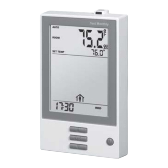
The thermostat is an electronic on/off
thermostat for temperature control by means of
an NTC sensor located either externally or
internally within the thermostat. The thermostat
has a built-in ground fault circuit interrupter
(GFCI, Class A). The thermostat and GFCI are
dual mode, suitable for 120/240 V 50/60 Hz
power supplies.
The thermostat is for flush mounts in a wall
socket.
Product summary
Thermostats with built-in GFCI
088L5130 Programmable thermostat incl. floor
sensor and air sensor
088L5132 Programmable thermostat for
laminate and engineered wood
088L5133 Non-Programmable thermostat incl.
floor sensor.
Power module with built-in GFCI
088L5135 Power module (15A)
Mounting of floor sensor (fig. 3)
The floor sensor is used for floor temperature
regulation. To facilitate replacement, the sensor
can be installed in a tube positioned between
two runs of the heating cable. The tube should
be terminated at the floor surface and sealed.
If required, the sensor cable can be extended
up to approx. 100 m using standard installation
cable. Two wires in a multi-core cable used to
supply power for the heating cable must not be
used.
It is not intended that the temperature sensor
wire shall enter through the wall socket
mounting box, but enter through one of the
front holes (see fig. 7.) in the thermostat housing
outside of the mounting box.
The sensor cable shall be seperated from
LINE and LOAD cables. Can be separated in
conduite, inside or outside the wall. (see fig. 7).
Other approved floor sensors can be used if
they comply with the technical specifications
(see fig. 5).
Mounting of thermostat with air sensor
(088L5132) (fig. 4)
The air sensor is used for comfort temperature
regulation in rooms. The thermostat should be
mounted on the wall approx. 5.4 ft (1.6m) above
the floor in such a way as to allow free air
circulation around it. Draughts and direct
sunlight or other heat sources must be avoided.
Mounting of thermostat
Installation
TO AVOID ELECTRIC SHOCK, DISCONNECT
THE HEATING SYSTEM POWER SUPPLY AT
THE MAIN PANEL BEFORE INSTALLING THE
THERMOSTAT.
KEEP THERMOSTAT AIR VENTS CLEAN AND
FREE FROM OBSTRUCTION.
This thermostat is an electrical product and
must be installed in compliance with the
National and/or Local Electrical Code.
Installation must be performed by qualified
personnel where required by law. The
thermostat is equipped with a ground fault
circuit interrupter (GFCI, Class A) which requires
that the line and load cables are isolated from
one another for correct operation. The
thermostat is designed for resistive load. The
resistive load must not exceed 15 A (1800 W at
120 Vac / 3600 W at 240 Vac).
During a ground fault, both power feeds will be
disconnected.
Line terminals: L1 (L), L2 (N)
Delivers power from the service panel (breaker
panel or fuse box) to the thermostat.
This cable must only be connected to the
thermostat's line terminals, marked L1 (L) and
L2 (N).
Load terminals
Delivers power from the thermostat to the
heating cable or mat.
This cable or mat must only be connected to
the thermostat's load terminals, marked
"LOAD".
1. Use a screwdriver to release the catch (fig. 1),
and remove the front cover
2. Connect cables according to the diagram (fig. 2)
3. Mount the thermostat in the wall socket.
4. Carefully replace the front cover by first
positioning its upper edge and then clicking it
into place.
Floor sensor
The floor sensor must be connected to
terminals marked "sensor", terminals C and D.
(fig. 6).
Power module, 088L5135
If loads of more than 15 A are required,
expansion is possible using power modules.
Power modules can be connected to the line
cable and load cable, see above.
Maximum distance between thermostat and
power modules is 80 ft (25 m).
Use field wiring cable, recommended min. 20
AWG. Connect A to C and B to D (fig. 6).
Operation
088L5130/5132 (Programmable):
The first time the thermostat is connected,
time and day must be set. The thermostat will
automatically start up in the menu for setting
time and day.
088L5133 (Non-programmable):
The actual temperature setting is shown and the
thermostat is ready for use.
Checking the GFCI
It is important that the GFCI is checked for
correct installation and function.
To check the GFCI:
Testing can only be performed while the
thermostat is calling for heat.
Adjust the setpoint until the heating symbol (
appears. Use the "Up" button to increase the
heating demand and then press the "OK"
button. Wait 10 seconds to allow the thermostat
to adjust to the new setpoint.
Then press the "TEST" button.
The test is successful if the red light in the
"TEST" button lights up and "GROUND FAULT"
is shown on the display. If this does not occur,
check the installation.
Press the "Standby/Reset" button to reset the
GFCI.
The red light should go out and the display
returns to normal appearance.
Press the "Down" button to return to the original
temperature setting.
© 2009 Danfoss Inc.
If the test fails, check the heating cable and
thermostat.
The GFCI should be tested monthly.
If during normal operation the GFCI trips
without the "TEST" button being pressed, there
could be a ground fault! To check whether it is a
ground fault or nuisance tripping, press
"Standby/Reset". If this causes the red light to
go off and stay off, it was nuisance tripping and
the system is operating correctly. If this does
not occur, there is a ground fault!
Check the heating cable, sensor cable and
thermostat. Replace the defective part.
Programming the thermostat (if applicable)
See user manual.
Floor sensor faults
If the floor sensor is disconnected or short-
circuited, the heating system is switched off.
The sensor can be checked against the
resistance table (fig. 5).
Error codes
E0: Internal error. The thermostat must be
replaced.
E1: Air sensor short-circuited or disconnected.
The thermostat must be replaced (n/a for
088L5133)
E2: Floor sensor short-circuited or
disconnected.
UL Listed for the US and Canada
According to the following standards:
Thermostat:
UL 873
CSA C22.2 No. 24.
UL file number: E157297
GFCI:
UL 943 4th ed.
CSA C22.2 No. 144.1-06
Classification
The product is a class II device (enhanced
insulation) and must be connected to the
following leads:
Phase L1 (L) 240 V ±10%, 50/60 Hz or
120 V ±10%, 50/60 Hz
Neutral L2 (N)
Max. load 15 A (resistive load)
The terminals are suitable for field wiring cables
of 12 to 22 AWG.
Technical data
Supply . . . . . . . . . . . . . .120/240 Vac 50/60 Hz
Load
. . . . . . . . . . .max. 15 A (resistive load)
Power
. . . . . . . . . . . . . . . .1.800 W at 120 Vac
. . . . . . . . . . . . . . . .3.600 W at 240 Vac
GFCI
. . . . . . . . . . . .Class A (5 mA trip level)
Temperature range +5 to +40°C, +41 to +104°F
)
Amb. temp. range . . . .0 to +25°C, +32 to +77°F
Advertisement

Related Manuals for Danfoss 088L5130


Summary of Contents for Danfoss 088L5130
- Page 1 INSTA LLATI O N M AN U AL Part No. 088L5130 / 5132 / 5133 / 5135 57143A 10/09 (DJU) English resistive load must not exceed 15 A (1800 W at If the test fails, check the heating cable and 120 Vac / 3600 W at 240 Vac).
- Page 2 Thermostat avec disjoncteur de fuite à la terre seront coupées. vérifié mensuellement. intégré 088L5130 Thermostat à horloge incluant une Câble d’alimentation Si le disjoncteur de fuite à la terre intégré se sonde de sol Achemine la puissance du panneau de service déclenche pendant l’opération normale sans...
- Page 3 Neutro L2 (N) Funcionamiento Carga máxima:15 A (carga resistiva) Se puede utilizar otros sensores de piso apro- 088L5130/5132 (con reloj incorporado): bados si estos cumplen con las especificacio- La primera vez que se conecta el termostato, Los terminales son compatibles con alambres nes técnicas (ver la fig.
- Page 4 Fig. 6 Danfoss can accept no responsibility for possible errors in catalogues, brochures, other printed materials, and website information. Danfoss reserves the right to alter its products without notice. This also applies to products already on order provided that such alteration can be made without subsequent changes being necessary in speci cations already agreed upon. All trademarks in this material are property of the respective companies.
Need help?
Do you have a question about the 088L5130 and is the answer not in the manual?
Questions and answers