
Related Manuals for DW DWC-B1362TIR650


Summary of Contents for DW DWC-B1362TIR650
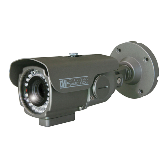
- Page 1 High Resolution Bullet Camera DWC-B1362TIR650 ABOUT MANUAL Before installing and using the camera, please read this manual carefully. Be sure to keep it handy for future reference. 08092012...
- Page 2 PRECAUTIONS Do not open or modify. Do not open the case except during maintenence and installation, for it may be dangerous and can cause damages. Do not put objects into the unit. Keep metal objects and flammable substances from entering the camera. It can cause fire, short-circuits, or other damages.
-
Page 3: Table Of Contents
Table of Contents Introduction Features Parts and Descriptions Dimensions Installation Included Accessories Surface Mount Installation Connecting to Monitors Camera’s Control Board Adjusting the Camera’s Lens Adjusting the Camera’s Angle Troubleshooting Warranty Information 14-15 Specifications 16-17 Memo 18-19... -
Page 4: Features
FEATURES* 1/3” Sony Super HAD Ⅱ CCD 570TV Lines (B/W), 540TV Lines (Color) 6 ~ 50mm Varifocal Auto Iris Lens 250ft Range IR with Intelligent Camera Sync True Day & Night / TDN5 (Electro Magnetic Mechanism) DRC (Dynamic Range Compressor) HME (Highlight Masking Exposure) SLC (Side Light Compensation) AGC / BLC / AWB... -
Page 5: Parts And Descriptions
PART & DESCRIPTIONS* RS 485 OPTION Front Case Rear Case BNC Jack Zoom, Focus Housing Control Board Power Input Connector DC 12V / AC24V Voltage Sunshield Con Cap Assembly Screw Lens Double Arm Bracket Fixing Screw Set Screw... -
Page 6: Dimensions
DIMENSIONS IN MILLIMETERS* 230.0 (9.05”) 86.5 (3.4”) 96.5 (4.8”) (3.8”) (3.07”) (0.2”) (2.67”) (3.77”) (2.67”) -
Page 7: Inside The Box
INSIDE THE BOX* Included with B2 Bullet Camera User Manual L-Key Mounting Template Double-Sided TORX-T20 Hex Key 4 Machine Screws and 4 Dry Wall Anchors Secondary Video-BNC Cable Bullet Camera ABOUT MANUAL Before installing and using the camera, please read this manual carefully. Be sure to keep it handy for future reference. -
Page 8: Surface Mount Installation
SURFACE MOUNT INSTALLATION INSTRUCTIONS* Use the 4 mounting screws to install the camera on the wall or ceiling. Then, follow the next step on the pages 9-12. NPT 3/4” Pipe *Installation Using a Junction Box *Note: Electrical junction box and required screws sold separately. -
Page 9: Connecting To Monitors
CONNECTING TO MONITORS* Use the diagram below to connect to a Monitor or CRT Monitor properly. 12VDC/24VAC CCTV Monitor Left Right Down Second Video Output Monitor Power connection - 12VDC/24VAC Dual Voltage (Auto Polarity Detection and Protection) All camera are equipped with a second video output for on-site configuration. -
Page 10: Control Board
CONTROL BOARD* Joystick: Controls the OSD menu. Secondary Connector: Video Output Connector for On-Site Configuration Remove clear plastic ring from the control cap. Turn control cap counter-clockwise until cap separates completely from the camera body. -
Page 11: Adjusting The Camera's Lens
ADJUSTING THE CAMERA LENS* Follow the instructions provided below to make any lens adjustments. ZOOM FOCUS To adjust the field of view, use the L-Key to turn the zoom screw (located on the bottom of the camera) counter-clockwise to zoom in, or clockwise to zoom out. Adjust the focus the same way as descriped above AFTER the desired zoom position is established. -
Page 12: Adjusting The Camera's Angle
ADJUSTING THE CAMERA ANGLE* CAUTION : Do not rotate more than 360 Do not unnecessarily twist too many times. - Page 13 TROUBLESHOOTING Before sending your camera for repair, check the following or contact our technical specialist. FOR NO VIDEO Check the coaxial cable and make sure it is connected securely. Check the lens’ iris adjustment at the camera’s OSD menu. Check the power supply and make sure the camera has the proper voltage and current.
-
Page 14: Warranty Information
WARRANTY INFORMATION* Digital Watchdog (referred to as “the Warrantor”) warrants the Digital Watchdog Camera against defects in materials or workmanship as follows: LABOR : For the initial five (5) years and one (1) year on IR LED from the original purchase date, if the camera is determined to be defective, the Warrantor will repair or replace the unit with a new or refurbished product at its option at no charge. - Page 15 LIMITS AND EXCLUSIONS* There are no express warranties except as listed above. The Warrantor will not be liable for incidental or consequential damages (including without limitation or damage to recording media), resulting from the use of these products or arising out of any breach of the warranty.
- Page 16 SPECIFICATION* VIDEO Image Sensor 1/3" CCD Total Pixels 811 (H) x 508 (V), 411K Pixels Effective Pixels 768 (H) x 494 (V) Scanning System 525 Lines, 2 : 1 Interlace Frequency 15.734KHz (H), 59.95Hz (V) Synchronization Internal / Line Lock Horizontal Resolution 540 TV Lines [Color], 570 TV Lines [B&W] Minimum Illumination...
- Page 17 SPECIFICATION* OPERATIONAL Day & Night Mode AUTO / COLOR / B&W Mirror OFF / ON Sharpness 0-49 OFF / ON OFF / ON 3D Digital Noise Reduction OFF / ON (0-100) Dynamic Range Compressor OFF / ON Privacy Zones OFF / ON (4 Programmable Zones) Language ENGLISH /CHINESE ENVIRONMENTAL...
- Page 18 MEMO*...
- Page 19 MEMO*...
- Page 20 5436 W Crenshaw St. Tampa, FL 33634 Tel : 866-446-3595 / 813-888-9555 Fax : 813-888-9262 www.Digital-Watchdog.com technicalsupport@dwcc.tv Technical Support Hours : Monday-Friday 8:30am to 8:00pm Eastern Time...
Need help?
Do you have a question about the DWC-B1362TIR650 and is the answer not in the manual?
Questions and answers