Table of Contents
Troubleshooting

Related Manuals for Generac Power Systems XD5000E


Summary of Contents for Generac Power Systems XD5000E
- Page 1 XD5000E Diesel Portable Generator Owner’s Manual 000703 MODEL:________________________ SERIAL:________________________ DATE PURCHASED:______________ Register your Generac product at: WWW.GENERAC.COM 1-888-GENERAC SAVE THIS MANUAL FOR FUTURE REFERENCE...
-
Page 2: Table Of Contents
Table of Contents Section 1 Introduction and Safety 1 Section 4 Maintenance and Introduction ........1 Troubleshooting ......14 Safety Rules ........1 Maintenance Recommendations ...14 Safety Symbols and Meanings ..1 Maintenance Schedule ....14 Exhaust and Location Hazards ..2 Preventive Maintenance ....14 Electrical Hazards ...... -
Page 3: Section 1 Introduction And Safety
Section 1 Introduction and Safety Introduction Thank you for purchasing a Generac Power DANGER Systems Inc. product. This unit has been designed to provide high-performance, effi- Indicates a hazardous situation which, if not avoided, will cient operation, and years of use when main- result in death or serious injury. -
Page 4: Exhaust And Location Hazards
Exhaust and Location Hazards DANGER Electrocution. Turn utility and emergency DANGER power supplies to OFF before connecting power Asphyxiation. Running engines produce carbon source and load lines. Failure to do so will result monoxide, a colorless, odorless, poisonous gas. in death or serious injury. (000116) Carbon monoxide, if not avoided, will result in death or serious injury. -
Page 5: Fire Hazards
This list is not all inclusive. Check with the WARNING Authority Having Jurisdiction (AHJ) for any local codes or standards which may be appli- Accidental Start-up. Disconnect the negative battery cable to your jurisdiction. cable, then the positive battery cable when working on unit. -
Page 6: Section 2 General Information And Setup
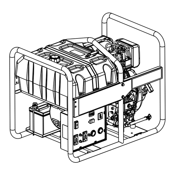
Section 2 General Information and Setup 000703 000711 Figure 2-1. Features and Controls TABLE 1. Generator Components Fuel Filter 120 Volt AC, 20 Amp, GFCI Duplex Receptacle Engine On/Off Lever 120/240 Volt AC, 30 Amp Locking Fuel On/Off Receptacle Voltage Selector Switch 120 Volt AC, 30 Amp Locking Receptacle Fuel Primer Bulb 20 Amp Circuit Breakers... -
Page 7: Know Your Generator
Emissions Information The U.S. Environmental Protection Agency, EPA, (and California Air Resource Board, CARB, for equipment certified to CA stan- dards) require the generator comply with exhaust emission standards. The generator is certified to meet applicable EPA and CARB emission levels using Ultra Low Sulfur fuel, Diesel No. -
Page 8: Hour Meter
Hour Meter The Hour Meter tracks hours of operation for scheduled maintenance. See Figure 2-4. • The CHG OIL display will illuminate every 100 hours. The message will flash one hour before and one hour after each 100 hour interval, providing a two hour window to perform service. -
Page 9: Remove Contents From Carton
Remove Contents from Carton 4. Record model, serial number, and date of purchase on front cover of this manual. 1. Open carton completely by cutting each corner from top to bottom. Assembly 2. Remove and verify carton contents prior to assembly. -
Page 10: Battery Installation (If Equipped)
10. Tighten wing nuts until the lock washers are compressed to being flat. NOTE: If the battery is unable to start the engine, charge it with the 12V charger included in the accessory box (see the "Charging a Battery" section for details). 000710 Figure 2-9. -
Page 11: Fuel
4. Add recommended engine oil. NOTE: Some units have more than one oil fill location. It is only necessary to use one oil fill point. 5. Thread dipstick into oil filler neck. Oil level is checked with dipstick fully installed. 6. -
Page 12: Section 3 Operation
Section 3 Operation Operation and Use Questions Grounding the Generator When Used as a Portable Call Generac customer service at 1-888-GEN- ERAC with questions or concerns about The generator is equipped with an equipment equipment operation and maintenance. ground connecting the generator frame and the ground terminals on the AC output recep- Before Starting Engine tacles (see NEC 250.34 (A). -
Page 13: Transporting/Tipping Of The Unit
• The rated wattage of lights can be taken *Garage Door Opener 500 to 750 from light bulbs. The rated wattage of tools, Hair Dryer 1200 appliances, and motors can be found on a data label or decal affixed to the device. Hand Drill 250 to 1100 •... -
Page 14: Starting Pull Start Engines
Starting Pull Start Engines WARNING Recoil Hazard. Recoil could retract unexpectedly. Kickback could result in death or serious injury. (000183) CAUTION Equipment and property damage. Disconnect electrical loads prior to starting or stopping unit. Failure to do so 000714 could result in equipment and property damage. (000136) Figure 3-4. -
Page 15: Low Oil Pressure Switch
Generator Shut Down CAUTION Equipment and property damage. Disconnect electrical loads prior to starting or stopping unit. Failure to do so could result in equipment and property damage. (000136) 1. Turn main breaker switch Off. 2. Switch engine start switch to Off. 3. -
Page 16: Section 4 Maintenance And Troubleshooting
Section 4 Maintenance and Troubleshooting Maintenance Recommendations Preventive Maintenance Regular maintenance will improve perfor- Dirt or debris can cause improper operation mance and extend generator life. See a quali- and equipment damage. Clean generator fied dealer for service. daily or before each use. Keep area around and behind muffler free from combustible Generator warranty does not cover items sub- debris. -
Page 17: Battery Replacement (If Applicable)
Inspect Engine Oil Level Change oil while engine is still warm from run- ning, as follows: 1. Place generator on a level surface. WARNING 2. Clean area around oil fill, and oil drain Risk of burns. Allow engine to cool before draining plug. -
Page 18: Valve Clearance
Storage 2. Disconnect positive (+) battery terminal SECOND (B). 3. Loosen wing nuts and remove battery bracket and hardware. General 4. Replace battery by following instructions in "Battery Installation (if equipped)." DANGER section. Explosion and Fire. Fuel and vapors are extremely flammable and explosive. -
Page 19: Troubleshooting
Return Engine to Service NOTE: Always treat diesel fuel for long term storage. Use the approved fuel addi- 1. Refer to the "Before Starting Engine." tive and water abatement material. Test section. stored fuel every 90 days and provide addi- 2. - Page 20 PROBLEM CAUSE CORRECTION 1. Out of fuel. 1. Fill fuel tank. Prime fuel sys- "Starting Pull Start 2. Low oil level. tem. See 3. Fault in engine. Engines." "Starting Elec- 4. Ambient temp too high. tric Start Engines." Engine shuts down 2.
-
Page 21: Notes
Notes Operator’s Manual for Portable Generator... - Page 22 Operator’s Manual for Portable Generator...
- Page 24 Part No. 0L3191 Rev. A 06/18/15 Generac Power Systems, Inc. Printed in USA S45 W29290 Hwy. 59 ©2015 Generac Power Systems, Inc. All rights Waukesha, WI 53189 reserved 1-888-GENERAC Specifications are subject to change without notice. generac.com No reproduction allowed in any form without prior...
Need help?
Do you have a question about the XD5000E and is the answer not in the manual?
Questions and answers