Table of Contents
Advertisement
Advertisement
Table of Contents

Related Manuals for Harman Kardon AVR 350


Summary of Contents for Harman Kardon AVR 350
- Page 1 AVR 350 AUDIO/VIDEO RECEIVER OWNER’S MANUAL...
-
Page 2: Safety Information
SAFETY INFORMATION home, consult your product dealer or local power company. 18. Overloading. Do not overload wall outlets, extension CAUTION For products intended to operate from battery power, or cords, or integral convenience receptacles, as this can result RISK OF ELECTRIC SHOCK other sources, refer to the operating instructions. -
Page 3: Important Safety Information
It is important that you remove the protective plastic film from the front-panel lens. • Due to the weight of the AVR 350 and the heat generated by the amplifiers, Leaving the film in place will affect the performance of your remote control. - Page 4 STAPLE INVOICE HERE...
-
Page 5: Table Of Contents
Step Nine – Remote IR Inputs and Output 63, 66 Trademark Acknowledgements APPENDIX Step Ten – Install a Multiroom System Step Eleven – Turn On the AVR 350 INITIAL SETUP Using the On-Screen Menu System Configure the AVR 350 Using EzSet/EQ WARNING... -
Page 6: Introduction
INTRODUCTION Please register your AVR 350 on our Web site at www.harmankardon.com. Note: You’ll need the product’s serial number. At the same time, you can choose to be notified about our new products and/or special promotions. WWW.HARMANKARDON.COM Thank you for choosing Harman Kardon ®... -
Page 7: Audio Inputs
Supplied Accessories Transcodes composite and S-video to component video The following accessory items are supplied with the AVR 350. If any of these items are missing, please contact Harman Kardon customer Transcodes 480i video to HDMI format, with upscaling up to 720p service at www.harmankardon.com. -
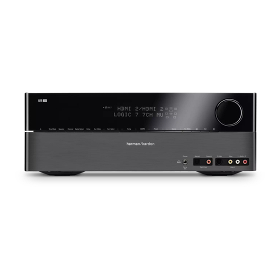
Page 8: Front-Panel Controls
It is important to ensure that it is not blocked. Message Display. For traffic-and-weather channels, this button displays If covering the sensor is unavoidable, such as when the AVR 350 is the city, channel name, local weather and local temperature. -
Page 10: Rear-Panel Connections
Remote Infrared (IR) Input and Output: When the remote IR video signals between devices. With the AVR 350’s powerful processor, receiver on the front panel is blocked, such as when the AVR is placed you may connect up to two HDMI-equipped source devices to the HDMI... -
Page 11: Rear-Panel Connections
REAR-PANEL CONNECTIONS The AVR 350 is Simplay HD-verified for compatibility via the HDMI • Due to the design of some video displays, analog 480p or connection with other Simplay HD-verified products. 720p component video source signals may produce artifacts when used with the AVR’s analog video outputs (composite,... -
Page 13: Main Remote Control Functions
MAIN REMOTE CONTROL FUNCTIONS The AVR 350 remote is capable of controlling 11 devices, including the IR Transmitter Lens: As buttons are pressed on the remote, AVR itself and an iPod docked in the optional The Bridge accessory. infrared codes are emitted through this lens. Make sure it is pointing During the installation process, you may program the codes for each toward the component being operated. - Page 14 IR Transmitter Lens Power On Mute Program Indicator Power Off AVR Selector Input Selectors 6-/8-Channel Input Selector AM/FM XM Radio Learn Test Tone TV/Video Sleep Volume Controls DSP Surround Multiroom On-Screen Display Speaker Setup Channel Level Navigation Digital Input Delay Numeric Keys Tuning Mode Memory...
- Page 15 Advanced Functions section for more information on using the tuning mode has been set to manual or automatic, each press will either change one frequency step at a time, or seek the next frequency with AVR 350’s multiroom system. acceptable signal strength. Channel Level:...
-
Page 16: Zone Ii Remote Control Functions
AVR itself is in Standby mode. When in the main listening room, deck or an iPod docked in The Bridge is in use, these buttons may be press any Input Selector or the AVR Selector to turn on the AVR 350, used to fast-play forward or backward within a track. - Page 17 IR Transmitter Mute Power Off AVR Selector Input Selectors AM/FM/XM Radio Preset Up/Down – Tuning Up/Down – Track Skip Fast Play Play Stop Disc Skip Pause Volume Controls NOTE: To make it easier to follow the instructions throughout the manual that refer to this illustration, a copy of this page may be downloaded from the Product Support section at www.harmankardon.com.
-
Page 18: Introduction To Home Theater
The result is a rich variety of surround mode options. Some modes are The AVR 350 may have up to seven speakers connected directly to it selected automatically, depending on the signal being received from (plus a subwoofer). -
Page 19: Connections
Connecting Source Devices to the AVR terminals, performance can suffer, especially for the low frequencies. The AVR 350 is designed to process audio and video input signals, Always connect the positive terminal on the loudspeaker, which is usually colored red, to the positive terminal on the receiver, which is colored as playing back the audio and displaying the video on a television or shown in the Connection Color Guide (Table 1). -
Page 20: Audio Connections
Figure 4 – HDMI Connection The AVR 350 is Simplay HD-verified for compatibility via the HDMI HDMI cable runs are usually limited to about 10 feet. The AVR 350 connection with other Simplay HD-verified products. incorporates a repeater, which allows an additional 10 feet of cable There are different versions of HDMI, depending on the capability of the between the source device and the video display. -
Page 21: Analog Audio
The AVR 350 is only Digital Video capable of processing one PCM source at a time. -
Page 22: Antennas
S-video and then for “car and home use, ” you will not be able to enjoy the AVR 350’s composite video. ease of control. -
Page 23: Speaker Placement
Placement of the surround speakers depends on the number of speakers in your system. If you’re using only two speakers with the AVR 350, place them in the front left and right positions, and skip to the Installation section. However, Harman Kardon recommends using the AVR 350 in a 5.1- or 7.1-channel configuration for optimal... -
Page 24: Installation
XM antenna module designed for connection to an XM Ready device, plug any of the power cords back in until you have finished such as the AVR 350, you may connect it now. To enjoy XM Radio, making all of your connections. - Page 25 Table 2 (below) in order to simplify programming your receiver and remote control. However, you may connect any device to any source input. Table 2 – Recommended Source Component Connections Source Device Type AVR 350 Source Input Audio Connections Video Connections VCR, DVR, PVR, Video 1 •...
-
Page 26: Video 4 Source
Video 2 Source video output to the matching Video 4 video input. See Figure 23. The Video 2 source is used only for playback. The AVR 350 remote control is programmed to operate many brands and models of cable and satellite television devices, and we recommend connecting your cable or satellite set-top box to this source. - Page 27 Video 3) and select that source input, then select the 6-/8-Channel to the DVD inputs, or to one of the HDMI inputs, if the source decodes Inputs for audio; the AVR 350 will retain the last video selection other the audio and outputs it through the HDMI connection.
-
Page 28: Step Five - Connect Video Display
50 watts. The device should have its mechanical or master 1080p analog video signals to the HDMI format and outputs 1080i power switch turned on, and it will power on any time the AVR 350 is signals, as is, to the Component Video Outputs. This affects users turned on. -
Page 29: Step Seven - Insert Batteries In Remote
When using the remote, remember to point the lens toward the front panel of the AVR 350. Make sure no objects, such as furniture, are 1. Using the codes in Tables A9–A17 of the Appendix, look up the blocking the remote’s path to the receiver. - Page 30 The remote then exits Program mode. Figure 38 – Learning Remote Commands c) Press the button on the AVR 350 remote you wish to program with 5. Once you have programmed a code, it’s a good idea to try using the new code, and the Program Indicator will light steadily in amber.
-
Page 31: Step Nine - Remote Ir Inputs And Output
Figure 39 – IR Inputs and Outputs install the multiroom system. When the AVR 350 is placed in such a way that aiming the remote at 1. Connect an external amplifier to the Multiroom Audio Outputs. the front-panel IR sensor is difficult, such as inside a cabinet or facing See Figure 40. -
Page 32: Step Eleven - Turn On The Avr 350
Figure 44 – Power Switches This method may be used when it is more important to distribute 2. There are several ways in which the AVR 350 may be turned on from audio to additional rooms than to have a full 7.1-channel system in Standby mode. -
Page 33: Initial Setup
INITIAL SETUP Before you begin enjoying your new receiver, a few adjustments should be made to configure the AVR 350 to match your actual system. Make sure that you have connected a video display to one of the video monitor outputs on the receiver. When you turn on your display and the AVR, you should see a blue screen. -
Page 34: Configure The Avr 350 Using Ezset/Eq
Step Four – After you select “Continue” , the screen shown in Figure 54 else run EzSet/EQ. will appear. Although the AVR 350 may be used with up to eight speakers, you may have elected not to install surround back speakers at this time, Step One –... -
Page 35: What Ezset/Eq Does
Figure 57 – EzSet/EQ: Speaker Distance Test NOTE: The AVR 350 is also capable of setting a different type of delay, called A/V Sync Delay. A/V Sync Delay is used to compensate for lip sync problems that may occur when a video... -
Page 36: Configure Sources
INITIAL SETUP display device or set-top box causes delays while digital video is making these adjustments a screen similar to the one shown in signals are processed. It simultaneously adds a delay to all Figure 59 will appear. You may hear EzSet/EQ repeat tones from various speaker channels in the system. - Page 37 AVR’s HDMI Output to the display. The Use the Navigation Buttons to highlight the desired letter (or other AVR 350 transcodes analog source video signals up to 720p from character), and press the Set Button to add it to the new title, which composite, S-video or component video to the HDMI format, and will be displayed in the bar at the top of the screen.
- Page 38 AUTO POLL: The Auto Poll feature is used when both an analog audio and digital audio connection have been made for one source device. If for some reason no digital signal is available, the AVR 350 will switch to the analog inputs for the source. This situation can occur with some cable or satellite television broadcasts, where some channels are broad- cast with digital audio and others with analog audio.
-
Page 39: Operation
Figure 63 – Power Switches Figure 66 – Sleep Button There are several ways in which the AVR 350 may be turned on: When the sleep timer has been set, the front-panel display will automati- cally dim to half-brightness. If you press any button on the remote or a) Press the Standby/On Switch on the front panel. -
Page 40: Mute Function
Set Button. Once you have changed the setting using the Buttons, press the (see Figure 65). Since the AVR 350 allows for more source input ‹ › Set Button to enter the new setting. When you have finished, either wait devices than the remote has buttons for, some sources are required to share buttons. -
Page 41: Audio Input Selection
The VIDEO IN line of the Input Setup menu indicates which of the video inputs on the AVR 350 is assigned to each source. As shown in Table 5, If a signal is present at the component video input assigned to that by default the Component Video 1 input is assigned to the DVD source, source, it will be selected. -
Page 42: Channel Direct Inputs
Example 1: You would like to connect a DVD-Audio player to the To select the 6-/8-Channel Inputs as the source, use either the Source AVR 350. You plan on playing a variety of discs using this player, Selector on the front panel or press the 6/8CH Input Selector on the including conventional DVDs and even CDs, as well as multichannel remote. -
Page 43: Xm Radio Operation
XM Radio is a satellite-delivered service that offers hundreds of program channels, as well as local traffic and weather information for select cities. The AVR 350 is “XM Ready,” which means that it is able to receive the XM service when a user-supplied XM antenna module is connected and the service activated. -
Page 44: Recording
OPERATION 3. The AVR 350 is capable of storing up to 40 XM Radio preset channels. NOTES: The presets are divided into five banks, denoted by the letters A 1. Analog audio signals are not converted to digital form, and through E, with eight numeric presets per bank. - Page 45 AVR 350’s settings cannot override these iTunes settings. on the left, the play mode icon, and the time remaining on the right. In addition, if a video display is connected to the AVR 350, a screen will appear briefly to display information about the iPod’s status and the track.
-
Page 46: Selecting A Surround Mode
You are now ready to enjoy the best in home theater entertainment with available surround modes on the AVR 350, and you may find a few that your AVR 350. As you become more familiar with the receiver, you may become your favorites for certain sources or program types. -
Page 47: Advanced Functions
Dolby True HD and Dolby Digital Plus, may be available in 7.1-channel 1. Analog Bypass Mode: In this mode, the 2-channel signal is passed configurations in the future. The AVR 350 will not be able to play native directly to the volume control, without being digitized or undergoing 7.1-channel programs unless the source device outputs a 5.1- or... -
Page 48: Surround Modes
ADVANCED FUNCTIONS “3” is used with DTS-ES bitstreams to represent the presence of the a brief description of each mode the AVR 350 is capable of using, and discrete surround back channel in addition to the side surround left and also indicates the types of incoming signals or digital bitstreams the right channels. -
Page 49: Dolby Surround Settings
See Figure 88. Default Modes During initial use or after a processor reset, the AVR 350 will default to the Logic 7 7CH Music mode for all analog and PCM audio inputs. Subsequently, when a source input is selected and an analog or PCM signal is received, the AVR will switch to the last surround mode used for that source input/incoming signal combination. - Page 50 Dolby Pro Logic IIx modes may be selected not only with Dolby Digital bit- streams, but thanks to the AVR 350’s post-processor, they may also be used with some DTS bitstreams to add a surround back channel to 5.1 modes.
- Page 51 ADVANCED FUNCTIONS Surround Mode Description Incoming Bitstream or Signal Dolby Pro Logic IIx This mode is similar to Dolby Pro Logic II Music, including the availability • Dolby Digital 2/0/.0 or .1, 2/2/.0 or .1, Music of center width, dimension and panorama adjustments. Dolby Pro Logic IIx 3/2/.0 or .1, EX Music adds a surround back channel.
- Page 52 • Tuner 32kHz, 44.1kHz, 48kHz, 96kHz) • PCM ( Logic 7 The AVR 350 is programmed at the factory to default to this mode for • Analog (2-channel) Music 2-channel signals. Logic 7 Music mode is well suited to conventional •...
-
Page 53: Manual Setup
If you send the lowest notes to small satellite speakers, you won’t hear these notes very well, and you may even damage the speaker by The AVR 350 is flexibly designed to be used with almost any loud- exceeding its capabilities. If you send the highest notes to the special- speakers available. -
Page 54: Speaker Size Menu
NONE setting for the surround back speakers. Speaker Size Menu The AVR 350 is one of the few receivers in its class to include multi- room capability. With assignable surround back amplifier channels, set- Move the cursor to the Size line and press the Set Button to display the ting up a multiroom system is more convenient than ever, no longer Speaker Size submenu. -
Page 55: Speaker Crossover Menu
100Hz, 120Hz, 150Hz or 200Hz. Depending upon the frequency response of your speakers which you recorded in Step One – NOTE: If you are using a Harman Kardon HKTS speaker Determine Speaker Size, for each speaker group select the number system, select the SMALL setting for the LEFT/RIGHT, CENTER, that matches or is just above the low end of your speaker’s frequency... -
Page 56: Step Four - Setting Channel Output Levels Manually
With up to seven main channels plus a subwoofer, imaging becomes both more critical and more complex. Unlike the rotary balance control, the goal of the AVR 350’s channel output adjustment process is to examine the output level of each channel independently and ensure Figure 91 –... -
Page 57: Video Adjustments
Buttons to adjust the level as desired. receiver and in the semi-OSD display, as well as the current level setting If you would like to set your levels using the AVR 350’s internal test (varies between –10dB and +10dB). Press the Buttons to ⁄... -
Page 58: Multiroom Operation
Video Monitor Outputs, you may not be able to view 1080p materials, but 1080i sources will be passed through. In any event, when the If you wish to use the AVR 350 with more than one remote room, source signal is 1080i or 1080p, the semi-OSD messages will not you will need to purchase a multichannel external amplifier that enables appear, including the volume bar. -
Page 59: Operating The Multiroom System
Operating the Multiroom System The AVR 350’s multiroom system is accessed using the on-screen Multi The AVR 350 offers several system settings that allow you to make the Room Setup menu. Press the OSD Button to display the Menu System, receiver easier to use rather than directly affecting performance. -
Page 60: Dim Function
Advanced Remote Control Functions the System Setup menu. At the Default Volume Set line, select the The AVR 350 remote control not only operates the AVR 350, but it also desired volume setting, and activate the feature by setting Volume serves as a universal remote that may be programmed to operate many Default to ON. -
Page 61: Macros
Processor Reset Macros are used to program sequences of up to 19 commands that There may be instances when you wish to fully reset the AVR 350 to its are executed with a single button press. Macros are well suited for factory defaults, or the unit may behave erratically after a power surge. -
Page 62: Troubleshooting Guide
• Always press remote control buttons as gently as possible Additional information on troubleshooting possible problems with your AVR 350, or installation-related issues, may be found in the list of “Frequently Asked Questions” , which is located in the Product Support section of our Web site at www.harmankardon.com. -
Page 63: Technical Specifications
All features and specifications are subject to change without notice. Distortion (TIM) Unmeasurable Slew Rate 40V/µsec Harman Kardon and Logic 7 are trademarks of Harman International Industries, Incorporated, registered in the United States and/or other countries. EzSet/EQ, and Designed to Entertain are trademarks Bridge of Harman International Industries, Incorporated. -
Page 64: Appendix
APPENDIX Appendix – Default settings, worksheets, remote product codes Table A1 – Source Input Setting Defaults Source HDMI 1 HDMI 2 Video 1 Video 2 Video 3 Video 4 The Bridge/ CD Tape Tuner 6-/8- Channel Title TUNER Video Input Comp V 1 HDMI 1 HDMI 2 Comp V 2 Comp V 3 Composite Composite The Bridge/ Comp V1 Comp V1 Comp V1 Comp V1 Comp V1 Audio Input Coax 1... - Page 65 APPENDIX Table A4 – Source Input Settings Source DVD HDMI 1 HDMI 2 Video 1 Video 2 Video 3 Video 4 The Bridge/DMP Tape Tuner 6-/8-Channel XM Title Video Input Audio Input The Bridge/DMP Tuner 6-/8-Channel Tuner Auto Poll Surround Mode Tone Mode Bass Treble...
- Page 66 APPENDIX Table A6 – Remote Control Codes Source Input Product Type (circle one) Remote Control Code Video 1 VCR, PVR, DMC Video 2 Cable, Satellite Video 3 Video 4 CD, CDR Tape Cassette HDMI 1 DVD, VCR, PVR, Cable/Satellite, DMC HDMI 2 DVD, VCR, PVR, Cable/Satellite, DMC Table A7 –...
- Page 67 APPENDIX 51 52 53 54 55 56 Refer to the numbered buttons in Figure 97 when using the Function List. Figure 97 – Remote Control Function List Reference...
- Page 68 APPENDIX Table A8 – Remote Control Function List No. Button Name AVR Function DVD/HDMI 1/2 CD/CD-R Tape VCR (VID1) TiVo TV (VID3/VID4) (DMP) XM Bridge (VID1/HDMI 1/2) (VID1/HDMI 1/2) (VID2/HDMI 1/2) (VID2/HDMI 1/2) 1 Power On Power On Power On Power On Power On Power On/Off...
- Page 69 APPENDIX Table A8 – continued No. Button Name AVR Function DVD/HDMI 1/2 CD/CD-R Tape VCR (VID1) TiVo TV (VID3/VID4) (DMP) XM Bridge (VID1/HDMI 1/2) (VID1/HDMI 1/2) (VID2/HDMI 1/2) (VID2/HDMI 1/2) 43 0 44 Memory Memory Audio or Playlist Time Source Memory (DMC 250 onl y ) 45 Tuning Up...
- Page 70 PROSCAN ELECTROHOME PROTON EMERSON QUASAR RADIO SHACK FUNAI 161 163 FUTURETECH REALISTIC RUNCO GOLDSTAR/LG SAMPO GRUNDIG SAMSUNG HALL MARK SANYO HARMAN KARDON SCOTT HITACHI SEARS INFINITY SHARP INKEL SIEMENS SIGNATURE JC PENNEY SONY JENSEN SOUNDESIGN SPECTRICON KAWASHO SYLVANIA KENWOOD SYMPHONIC...
- Page 71 APPENDIX Table A9 – continued TV Manufacturer/Brand Setup Code Number TV Manufacturer/Brand Setup Code Number LOGIK TERA LUXMAN THOMSON MAGNAVOX TOSHIBA MARANTZ TOTEVISION MATSUI VIDEO CONCEPTS MEMOREX VIDTECH METZ WARDS YAMAHA MINERVA YORK MITSUBISHI YUPITERU ZENITH NATIONAL ZONDA NIKEI ONKING ONWA OPTONICA ORION...
- Page 72 002 003 004 007 008 012 FUNAI 076 095 124 TOSHIBA 112 155 GO VIDEO TOTEVISION GOLDSTAR/LG 018 107 UNITECH HARMAN KARDON 002 003 018 VECTOR RESEARCH HITACHI 040 048 VIDEO CONCEPTS 018 040 JC PENNEY 018 045 VIDEOSONIC JENSEN...
- Page 73 120 130 GENEXXA WARDS GOLDSTAR/LG 016 087 YAMAHA 019 031 053 135 169 HAITAI 099 214 YORK HARMAN KARDON 001 002 025 HITACHI INKEL JC PENNEY 098 147 JENSEN 176 195 196 KENWOOD 030 062 078 148 151 176 178 181...
- Page 74 ALPHASTAR DBS DENON 019 051 ALPHASTAR DSR 003 004 BIRDVIEW GOLDSTAR/LG 005 055 064 CHANNEL MASTER 320 321 325 HARMAN KARDON 001 002 068 CHAPARRAL 315 316 451 CITOH MAGNAVOX DRAKE 313 317 318 MARANTZ DX ANTENNA 331 352 379...
- Page 75 APPENDIX CBL Manufacturer/Brand Setup Code Number Table A15 – Remote Control Product Codes – TAPE SCIENTIFIC ATLANTA 183 203 221 Tape Manufacturer/Brand Setup Code Number SEAM HARMAN KARDON SIGNATURE 001 188 SPRUCER 053 081 177 STARCOM 002 011 163 STARGATE Table A16 –...
- Page 76 ® 250 Crossways Park Drive, Woodbury, New York 11797 www.harmankardon.com © 2007 Harman International Industries, Incorporated. All rights reserved. Part No. CQX1A1284Z...
Need help?
Do you have a question about the AVR 350 and is the answer not in the manual?
Questions and answers