
Related Manuals for SecurityMan IWATCHALARMD


Summary of Contents for SecurityMan IWATCHALARMD
- Page 1 User’s Guide MOBILE APP BASED Wireless Security Alarm System Model: IWATCHALARMD...
- Page 2 SecurityMan. The content of this manual is furnished for informational use only, is subject to change without notice, and should not be construed as a commitment by SecurityMan. SecurityMan Inc assumes no responsibility or liability for any errors or inaccuracies that may appear in this book.
- Page 3 The liability of SecurityMan Inc, arising from this warranty and sale shall be limited to a refund of the purchase price. In no event shall SecurityMan be liable for costs of procurement of substitute products or services, or for any lost profits, or for any consequential, incidental, direct or indirect damages, however caused and on any theory of liability, arising from this warranty and sale.
-
Page 4: Table Of Contents
Table of Contents Introduction Features Important Restrictions Package Contents Product Basics Alarm Host (SM-025H) Door / Window Sensor (SM-002M) Motion Sensor (SM-003P) Indoor Siren (SM-005SR) Remote Control (SM-007R) Quick Start Hardware Setup Alarm Host Door / Window Sensor Motion Sensor Indoor Siren Remote Control Smartphone Smart Config Method... - Page 5 HomeBot Control Center Features & Options Main Screen Symbols and Notifications Back Alarm Status Sensor Status Icons and Settings Silent Arm Disarm Camera (Optional SM-821DTH & SM-825DTH) Options and Settings Back Device List Area Camera Live View Settings and Options Back Snapshot Refresh...
- Page 6 Add (Refer to Adding Devices and Cameras) Enable / Disable Wall Socket (Optional Add-On) Wall Socket Options and Settings Back Device List Area Add (Refer to Adding Devices and Cameras) Enable / Disable Door / Window Sensor Door / Window Sensor Options and Settings Back Device List Area Add (Refer to Adding Devices and Cameras)
-
Page 7: Introduction
Introduction The SecurityMan IWATCHALARM is an App based wireless Security System that puts you in full control of your home or business security. The IWATCHALARM app lets you use your Smartphone or tablet to arm, disarm and monitor your security system at any time without service fees or contracts. - Page 8 • DO NOT use this product to carry out any illegal activities such as sneak preview, and etc. SecurityMan shall not be responsible for any consequences of illegal conducts made by users. • DO NOT put the plastic package bags in reach of children or babies. Young children can choke on these items if they put them into their mouths.
- Page 9 • DO NOT use the camera in the places which are covered with metal. The around metal, such as elevator and cabin, might shield the electromagnetic wave, and result in inability to receive signals.
-
Page 10: Package Contents
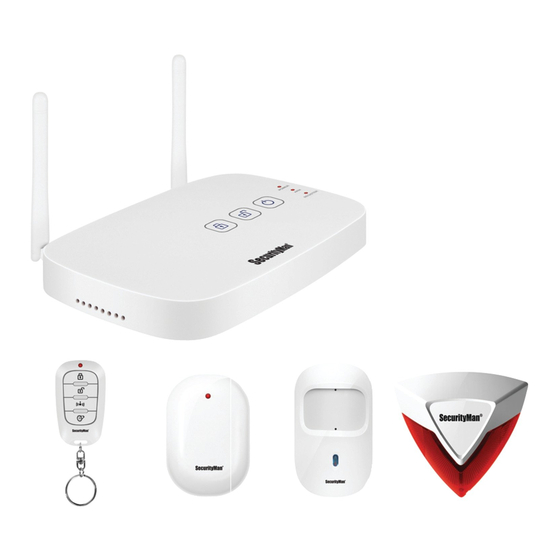
Package Contents SM-025H SM-002M SM-003P Alarm Host Door/ Window Sensor Motion Sensor SM-005SR SM-007R Mounting Indoor Siren Keychain Remote Accessories Power Adapter (2) Quick Start Quide User’s Manual (Host & Siren) Ethernet Cable Wall-Mount Bracket Warning Sign (Alarm Host) -
Page 11: Product Basics
Product Basics ALARM HOST (SM-025H) 1. Wi-Fi Antenna. 2. Wireless Antenna (433MHz). 3. Arm. 4. Disarm. 5. Power (press and hold to turn on/off). 6. Status LED’s. 7. AP (used as an alternative method when adding sensors). 8. Reset. 9. On/Off switch. 10. -
Page 12: Motion Sensor (Sm-003P)
1. Power LED (flashes on/off whenever a door or window is opened or closed). 2. Emitting sensor (normally mounted on the door or window frame). 3. Magnetic piece (normally mounted on the window or door). 4. Battery compartment (make sure all plastic is removed from the battery prior to inserting it, 1x AA battery). 5. -
Page 13: Remote Control (Sm-007R)
1. Strobe LED’s (flashes whenever the alarm is tripped). 2. Tamper switch (sets the siren off whenever it is lifted from its fixed location). 3. Power socket and cable management slot. 4. Pair button (used to add the siren to your alarm host). 5. -
Page 14: Quick Start
Quick Start NOTE: All sensors included with your kit have already been paired/synced to the alarm host and ready to go. Make sure you remove any plastic wraps from the batteries provided before inserting them. After powering up the host and all wireless sensors, please test all the senors first to ensure they operate well before mounting your sensors. - Page 15 MOTION SENSOR (SM-003P) Using a Philips screw driver, remove the screw located at the top of motion sensor, detach the front cover and Insert the 2 AAA batteries that were provided (Make sure the + and – polarities are correct). Once the batteries have been inserted the red LED should start to flash or stay solid indicating that it is now operable.
- Page 16 REMOTE CONTROL (SM-007R) Please pop open the top and back panels of the remote control to remove the clear plastic battery protector before use (please do this by hand only, do not use sharp utensil or screw driver). Once removed, place the top and back panels back together and test the remote by pressing any button.
- Page 17 2. Now select the Smart Config option (Fig 2.4) to begin the adding process. Turn your alarm host upside down then “Press and Hold” the pair button (Fig 2.5) until the pair LED located on the top of the host begins to flash rapidly and then press next on the Smartphone prompt.
-
Page 18: Door / Window Sensor
Adding Devices and Cameras By default right out the retail box, all the wireless devices are already paired to the alarm host. In situation where they are not paired, the HOMEBOT Smartphone app has a built in “user friendly” step-by-step interactive guide that you can follow when adding each device. - Page 19 2. On the control center, tap on the door/window sensor icon and then tap on the + (add) symbol to begin adding the new sensor. 3. “Press and Hold” the pair button on the door/widow sensor being added until the sensors LED begins to flash rapidly and then press next on the Smartphone prompt.
-
Page 20: Motion Sensor
MOTION SENSOR (SM-003P) 1. Using a Philips screw driver, remove the screw located at the top of motion sensor, detach the front cover and Insert the 2 AAA batteries that were provided. Once the batteries have been inserted the blue LED should flash indicating that it is now operable. - Page 21 3. “Press and Hold” the pair button on the motion sensor being added until the sensors LED begins to flash rapidly and then press next on the Smartphone prompt. Once your sensor has been detected by the alarm host you will be given the opportunity to name the device prior to saving it. 4.
-
Page 22: Indoor Siren
INDOOR SIREN (SM-005SR) 1. Insert the female end of the sirens AC adapter into the DC in port located behind the siren and the other end into a wall outlet closest to the alarm host. Make sure you place the siren face down leaving the pair button exposed. -
Page 23: Remote Control
4. Once the siren has been successfully added to the host you may unplug the AC adapter and mount the siren to your wall using the screws provided. Once the siren has been mounted, plug the AC adapter into a wall outlet. Please note that the siren is equipped with a tamper proof switch (located on the back) that will trigger the siren to go off whenever the siren is lifted off the wall. - Page 24 3. “Press and Hold” the pair button on the remote being added until the remotes LED begins to flash rapidly and then press next on the Smartphone prompt. Once your remote has been detected by the alarm host you will be given the opportunity to name the device prior to saving it.
- Page 25 DOORBELL (SM-105DB, optional add-on) 1. Remove the battery cover from the back of the doorbell by sliding it downward, insert the 2 AAA batteries that were provided and slide the cover back on. Once the cover is back on, test the doorbell by pressing the button and the red LED should flash with each press.
- Page 26 4. Once the doorbell has been successfully added to the host, you can mount it in the desired location. The back panel adhesive Velcro makes it convenient to remove at any time for portability. Mounting the DOORBELL (optional add-on) 1. Remove the backing on the slotted piece of Velcro and attach it to the back end of the doorbell as shown below. Make sure the slots align perfectly around the battery compartment so that it does not complicate changing the batteries later.
-
Page 27: Home Automation Wall Socket
2. Find a dry location for the door bell and screw in the abrasive piece of the Velcro using the screws provided. Then attach the doorbell to the abrasive end of the Velcro that was screwed into the wall and you are done. HOME AUTOMATION WALL SOCKET (SM-001SK, optional add-on) 1. - Page 28 3. “Press and Hold” the pair button on the socket being added until the LED begins to flash rapidly and then press next on the Smartphone prompt. Once your wall socket has been detected by the alarm host you will be given the opportunity to name the device prior to saving it.
-
Page 29: Basic Operations
Basic Operations The SM-001SK Home Automation Wall Socket allows you to control the ON and OFF function of any device that is connected to it, such as a Lamp, a radio, etc. To control the wall socket simply launch the control center on your Smartphone or tablet and select the Wall Socket icon. - Page 30 2. Make sure your Smartphone or tablet is connected to the same Wi-Fi network as the one you want to put the camera on and on the control center, tap on the camera icon and then tap on the + (add) symbol to begin adding the new camera. 3.
- Page 31 5. “Press and Release” the pair button on the back of the camera. At this point the green power LED located on the front of the camera will start to flash rapidly indicating that it is in pair mode. When you see the LED flashing rapidly press next on the Smartphone prompt.
-
Page 32: Wifi Fixed Camera
WIFI FIXED CAMERA (SM-825DTH, optional add-on) 1. Insert your Micro SD memory card (not included) into the TF slot. Then insert the female end of the AC adapter into the DC in port located behind the camera and the other end into a wall outlet closest to the alarm host. You can re-position the camera to a different location once it has been successfully paired to the host. - Page 33 3. Select the camera number you want to add the new camera to and then tap “yes” on the confirmation popup to proceed. NOTE: To remove a camera simply tap on any of the checked camera numbers and then confirm its removal by tapping on Yes at the prompt.
- Page 34 5. “Press and Release” the pair button on the back of the camera. At this point the green power LED located on the front of the camera will start to flash rapidly indicating that it is in pair mode. When you see the LED flashing rapidly press next on the Smartphone prompt.
-
Page 35: Homebot Main Screen Features & Options
6. Once your camera has been detected by the host the green power LED on the camera should start to flash steady. Now input the default camera password 123456 when prompted, tap save and then tap ok on the successfully registered prompt to complete the process. HomeBot Main Screen Features &... -
Page 36: Alarm Host Image
ALARM HOST IMAGE The alarm host image is immediately displayed once you have successfully added a new host to the HomeBot app and is mainly used whenever you need to access the apps control center. To access the control center simply tap on the alarm host image as shown in the image below. -
Page 37: Search In Lan
1. Search in LAN 2. QR Scan 3. Manual Input SEARCH IN LAN The Search in LAN options are specifically designed to perform searches over your Local Area Network quickly and efficiently while being easy enough to use that it doesn’t confuse you with hundreds of options. •... -
Page 38: Broadcast In Lan
Fig 1 Fig 2 Fig 3 2. Once your alarm host has been detected by the app the pair LED on the host will go out indicating that it was found. You will now be given the opportunity to name the alarm host (Fig 4) such as home, work, etc, prior to saving it. - Page 39 Fig 1 Fig 2 2. Make sure your Smartphone or tablet is connected to the same Wi-Fi network that the alarm host is connected to and tap on the Broadcast in LAN option (Fig 3) to display all connected devices on our network (Fig 4). Now locate the serial ID associated with your alarm host (Fig 5) and tap on it to proceed.
- Page 40 AP MODE To add your alarm host to the HomeBot app using the AP Mode method, make sure your new alarm host in pow- ered on and follow the steps below. 1. Tap on the AP Mode option (Fig 1) to begin the adding process. Turn your alarm host upside down then “Press and Hold”...
- Page 41 Fig 6 Fig 7 4. Once all LED’s on the alarm hast turn off “Press and Hold” the power button on the host (Fig 8) until the power LED turns back on. Wait 40-60 seconds for the host to boot up and then press “Next” on the Smartphone prompt (Fig 9).
-
Page 42: Qr Scan
Fig 10 Fig 11 Fig 12 QR SCAN Please follow the steps below to add your alarm host to the HomeBot app using the QR Scan method. 1. Insert the female end of the AC adapter into the DC IN port (Fig 1) located at the bottom of the host and connect the other end into a wall outlet. -
Page 43: Manual Input
Fig 3 Fig 4 Fig 5 MANUAL INPUT Please follow the steps below to manually add your alarm host to the HomeBot app. 1. Insert the female end of the AC adapter into the DC IN port (Fig 1) located at the bottom of the host and connect the other end into a wall outlet. -
Page 44: App Info
Fig 3 Fig 4 3. Now name the alarm host (Fig 5) such as home, work, etc, input the default host password 123456 and, tap save (Fig 5) to complete the setup. Your device will now be displayed as the start screen whenever the app is launched (Fig 6). -
Page 45: Modify System
MODIFY SYSTEM The Modify System option is used to change the systems name, password (if entered incorrectly during setup) or delete the host from the app. HomeBot Control Center Features & Options The HomeBot Control Center lets you take control of your alarm system using your mobile device. Through the control center you can add, remove and control all sensors and accessories from your phone or tablet. - Page 46 MAIN SCREEN SYMBOLS AND NOTIFICATIONS 1. Back 2. Sensor Status 3. Alarm Status BACK Used to exit the control center and return back to the start screen. SENSOR STATUS Represents the number of active/de-active devices per group (cameras, motion sensors, key remotes, etc). The first digit represents how many devices are enabled (active) and the second digit represents the total number of devices that have been added for that group.
- Page 47 The arm icon is used to arm your system using your mobile device. Once pressed, the alarm status icon will change to “locked” and the host’s “arm” LED will turn red. SILENT ARM The silent arm icon is used to arm your system in ”Silent Mode” (no noise from siren of host) using your mobile device.
-
Page 48: Back
CAMERA (for Optional SM-821DTH & SM-825DTH models) The camera icon is used to add, remove, edit and control the cameras that have been added to your system. To add, edit or control your camera(s) simply tap on the camera icon as shown below. CAMERA OPTIONS AND SETTINGS (Optional Add-on Cameras) 1. -
Page 49: Back
BACK Tapping on the Back Arrow will return you to the previous screen. DEVICE LIST AREA The device list area shows all the cameras that have been added. To login to a camera, simply tap on the camera you want to login too to bring up the camera live view as shown below. -
Page 50: Snapshot
CAMERA LIVE VIEW SETTINGS AND OPTIONS 1. Back 2. Snapshot 3. Refresh 4. Talk (2way) 5. Record 6. Camera Settings BACK Tapping on the Back Arrow will return you to the previous screen. SNAPSHOT Takes a snapshot of the current live view and saves it to your phones photo album. - Page 51 REFRESH Refreshes the connection between the phone and the camera, and should only be used when the live view becomes frozen, disconnected or unstable. When utilized, the HOMEBOT application will reattempt to reconnect to the camera. TALK Pressing and holding the microphone icon allows you to speak to the person on the other end of the camera being viewed.
-
Page 52: Camera Settings
RECORD Pressing the recording icon will start and stop (when pressed again) manual recoding for the camera being viewed. The recorded events will be stored on to the cameras micro SD card which can be played back later by pressing on the camera settings icon. CAMERA SETTINGS Tapping on the camera settings icon will allow you to change the camera time, date, passwords, and much more. -
Page 53: Did
Firmware Version Check Upgrade Change Password Change Admin Pass Motion Detection Event List Loop Record Storage Management Video Rotation Set Date & Time WLAN The Device ID (DID) section provides you with the cameras ID which is used to add the camera to the app, unique to each device and is not configurable. -
Page 54: Video Rotation
VIDEO ROTATION Video Rotation allows you to change the cameras flip the live view so that you can mount the camera upside down. SET DATE & TIME The set date & time option allows you to set the cameras time and date when needed. WLAN The WLAN option is used to set to connect your camera to your personal WIFI network. - Page 55 BACK Tapping on the Back Arrow will return you to the previous screen. DEVICE LIST AREA The device list area shows all the devices that have been added. To rename or remove a device, simply tap on the device and follow the options on the edit screen. ADD “+”...
-
Page 56: Wall Socket (Optional Add-On)
BACK Tapping on the Back Arrow will return you to the previous screen. DEVICE LIST AREA The device list area shows all the devices that have been added. To rename or remove a device, simply tap on the device and follow the options on the edit screen. ADD “+”... -
Page 57: Door/Window Sensor
BACK Tapping on the Back Arrow will return you to the previous screen. DEVICE LIST AREA The device list area shows all the devices that have been added. To rename or remove a device, simply tap on the device and follow the options on the edit screen. ADD “+”... -
Page 58: Motion Sensor
BACK Tapping on the Back Arrow will return you to the previous screen. DEVICE LIST AREA The device list area shows all the devices that have been added. To rename or remove a device, simply tap on the device and follow the options on the edit screen. ADD “+”... -
Page 59: Keychain Remote
BACK Tapping on the Back Arrow will return you to the previous screen. DEVICE LIST AREA The device list area shows all the devices that have been added. To rename or remove a device, simply tap on the device and follow the options on the edit screen. ADD “+”... -
Page 60: Alarm Log
BACK Tapping on the Back Arrow will return you to the previous screen. DEVICE LIST AREA The device list area shows all the devices that have been added. To rename or remove a device, simply tap on the device and follow the options on the edit screen. ADD “+”... -
Page 61: System Name Did
System Name Firmware Version Library Version Check Upgrade Change System Password Push Notification Set Date & Time Wi-Fi Networks SYSTEM NAME The System Name section is displays the name of the host and is not configurable through this part of the app. The Device ID (DID) section provides you with the host’s ID which is used to add the host to the app, unique to each device and is not configurable. -
Page 62: Specifications
Specifications SM-025H Power DC5V 1.0A Backup Battery Built-in Lithium (up to 6 hours standby time) Alarm Host Network WiFi or Ethernet Transmission Frequency 433MHz Host Buttons [Top] Arm, Disarm, Power [bottom] On/Off switch, Reset, AP (access point) LED’s (red) Power, Arm, Pair Ports Power, Ethernet Antennas... - Page 63 ADD-ON (Optional): SM-105DB Battery Powered 3V (2 x AAA batteries included, last up to 1 year) Doorbell LED’s Transmission Frequency 433MHz Button Size (LxWxH) 2.94” x 1.56” x .81” Transmission Distance up to 150ft with walls, 300ft clear line of sight SM-001SK Power Input AC100-240V...
- Page 64 SM-821DTH Lens 1/4 “ CMOS color Pan-Tilt WiFi/ Sensor OV9712 Eth IP Camera Focal Length 3.6mm Pan-Tilt Control 260:Horizontal 120:Vertical (no zoom) Viewing Angle 50 degree System P2P (Cloud Technology) Video Compression H.264 Resolution 720P HD (1280x720), VGA (640x480), QVGA (320x240) Video Rate 30fps Motion Detection...
- Page 65 If you encounter any difficulty in the operation of this product after reading the manual, please feel free to contact us. You can reach us by phone at 1-888-977-3777 from 8:30 AM to 5:30 PM Monday through Friday (Pacific Standard Time) or by email techsupport@securitymaninc.com. We will be happy to answer your questions and help you in any way we can.
- Page 66 www.securitymaninc.com...
Need help?
Do you have a question about the IWATCHALARMD and is the answer not in the manual?
Questions and answers