Table of Contents
Advertisement
Quick Links
Advertisement
Table of Contents

Related Manuals for Matrix G7-S12


Summary of Contents for Matrix G7-S12
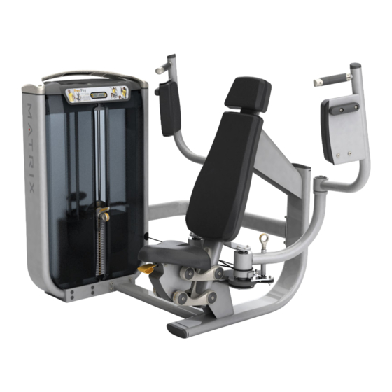
- Page 1 OWNERS MANUAL ULTRA Single-Station Strength G7-S12 Pectoral Fly...
-
Page 2: Table Of Contents
Table Of Contents Safety, General Care & Maintenence ........................3 Getting Started (Product Specifications) ......................5 Assembly Information .............................6 Markings ..................................7 Parts List ...................................8 Installation & Assembly: Value Line Part 1 Weight Stack & User Frame Assembly ..................10 Part 2 Seat Assembly ..........................12 Part 3 Arm Assembly .......................... -
Page 3: Safety, General Care & Maintenence
IMPORTANT SAFETY INSTRUCTIONS IMPORTANT SAFETY INFORMATION It is the sole responsibility of the purchaser of Matrix products to instruct all individuals, whether they are the end user or supervising personnel on proper usage of the equipment. It is recommended that all users of Matrix exercise equipment be informed of the following information prior to its use. - Page 4 IMPORTANT SAFETY INSTRUCTIONS WARNING: This product contains chemicals known to the State of California to cause cancer and birth defects or other reproductive harm. WARNING: SERIOUS INJURY CAN OCCUR ON THIS EQUIPMENT. FOLLOW THESE PRECAUTIONS TO AVOID INJURY! Never allow children on strength training equipment. Teenagers must be supervised at all times while using this equipment.
-
Page 5: Getting Started (Product Specifications)
GETTING STARTED EXERCISE PLACARD | PRODUCT SPECIFICATIONS | MAINTENANCE CHECKLIST EXERCISE PLACARD Start Finish Adjust start position for comfort Adjust seat height so elbows are slightly below shoulders with forearms on pads PRODUCT SPECIFICATIONS TECH SPECS Maximum User Weight 136 kg / 300 lbs. Maximum Training Weight 109 kg / 240 lbs. -
Page 6: Assembly Information
UNPACKING Thank you for purchasing a Matrix product. This machine is an EN957-1 and EN957-2 compliant Class S product. Your Matrix product is inspected before it is packaged. It is shipped in multiple pieces to facilitate the compact packaging of the machine. -
Page 7: Markings
MARKINGS WARNING LABEL LOCATIONS Hazard warning sticker [both arms]... -
Page 8: Parts List
Parts List DESCRIPTION Lower Connecting Tube M10 X 30L Socket Head Cap Screw M10 Flat Washer Weight Stack M10 Nylock Nut Upper Connecting Tube M10 X 75L Socket Head Cap Screw User Frame M10 Saddle Washer M8 X 25L Socket Head Cap Screw Medium Pivot Cap Seat Link Axle... - Page 9 Parts List DESCRIPTION Bumper Arm Pad M10 X 20L Button Head Cap Screw Head Rest Assembly M10 X 75L Button Head Cap Screw Back Pad Assembly M10 X 20L Hex Bolt Rear Shroud Left Front Shroud Right Front Shroud M8 X 60L Socket Head Cap Screw Top Cap...
-
Page 10: Part 1 Weight Stack & User Frame Assembly
ASSEMBLY PART 1: USER FRAME ASSEMBLY STEP 1 | WEIGHT STACK INSTRUCTIONS & NOTES DESCRIPTION QUANITY Lower Connecting Tube M10 X 30L SHC M10 Flat Washer Weight Stack M10 Nylock Nut Upper Connecting Tube M10 X 75L SHC Install the user frame hardware as shown, but DO NOT FULLY TIGHTEN . -
Page 11: User Frame
ASSEMBLY PART 1: USER FRAME ASSEMBLY STEP 2 | USER FRAME INSTRUCTIONS & NOTES DESCRIPTION QUANITY M10 X 30L SHC User Frame M10 Saddle Washer View A • Install the user frame hardware as shown, being sure to orient the saddle washer as shown in View A. -
Page 12: Part 2 Seat Assembly
ASSEMBLY PART 2: SEAT ASSEMBLY STEP 1 | SEAT LINK ASSEMBLY INSTRUCTIONS & NOTES DESCRIPTION QUANITY M8 X 25L SHC *Note: Shoulder Press Medium Pivot Cap seat assembly is shown - but steps and compo- Seat Link nents are identical for Axle the Pec Fly Spring Seat Tighten to 39 N-m/29 ft-... -
Page 13: Axle
ASSEMBLY PART 2: SEAT ASSEMBLY STEP 2 | SEAT ASSEMBLY INSTRUCTIONS & NOTES DESCRIPTION QUANITY M8 X 25L SHC Medium Pivot Cap Seat Link Axle Spring Rotate seat to engage pull pin Assemble upper axles, links and pivot caps Tighten to 39 N-m/29 ft-lbs. -
Page 14: Part 3 Arm Assembly
ASSEMBLY PART 3: ARM ASSEMBLY STEP 1 | RIGHT ARM ASSEMBLY INSTRUCTIONS & NOTES DESCRIPTION QUANITY Square end of axle Axle must be located Right Lower Arm Assembly as shown... -
Page 15: M5 Flat Washer
ASSEMBLY PART 3: ARM ASSEMBLY STEP 2 | RIGHT ARM ASSEMBLY INSTRUCTIONS & NOTES DESCRIPTION QUANITY M5 X 12L SHC M5 Flat Washer Axle Locking Sleeve Wave (Spring) Washer Torque to 7 N-m/5 ft-lbs. -
Page 16: Cam
ASSEMBLY PART 3: ARM ASSEMBLY STEP 3 | LEFT ARM ASSEMBLY INSTRUCTIONS & NOTES DESCRIPTION QUANITY Axle Spacer Left Lower Arm Assembly (w/pull pin) Square end of axle must be located as shown... - Page 17 ASSEMBLY PART 3: ARM ASSEMBLY STEP 4 | LEFT ARM ASSEMBLY INSTRUCTIONS & NOTES DESCRIPTION QUANITY M5 X 12L SHC M5 Flat Washer Axle Locking Sleeve Wave (Spring) Washer Torque to 7 N-m/5 ft-lbs.
-
Page 18: Rom Adjustment Cable
ASSEMBLY PART 3: ARM ASSEMBLY STEP 5 | ROM ADJUSTMENT CABLE ASSEMBLY INSTRUCTIONS & NOTES DESCRIPTION QUANITY M5 X 12L BHC ROM Adjustment Cable Cable Retainer Torque to 7 N-m/5 ft-lbs. - Page 19 ASSEMBLY PART 3: ARM ASSEMBLY STEP 5 | ROM ADJUSTMENT ASSEMBLY INSTRUCTIONS & NOTES Assemble “figure 8” cables as shown Tighten M12 jam nuts to 77 N-m/57 ft-lbs.
- Page 20 ASSEMBLY PART 3: ARM ASSEMBLY STEP 6 | UPPER ARM ASSEMBLY INSTRUCTIONS & NOTES DESCRIPTION QUANITY Medium Pivot Cap M10 X 20L SHC Snap Ring Washer (38 OD) Left Upper Arm Assembly Right Upper Arm Assembly (Not Shown) *Note: Only left side is shown, quantities reflect both left and right. Torque to 77 N-m/57 ft-lbs.
-
Page 21: Part 4 Pad Assembly
ASSEMBLY PART 4: PAD ASSEMBLY STEP 1 | ARM PAD ASSEMBLY INSTRUCTIONS & NOTES DESCRIPTION QUANITY M10 X 15L SHC M10 X 25L SHC Bumper Arm Pad M10 X 20L BHC *Note: Only right side is shown, quantities reflect both left and right. Install the pad as shown. Tighten to 27 N-m/20 ft-lbs. - Page 22 ASSEMBLY PART 4: PAD ASSEMBLY STEP 2 | BACK PAD ASSEMBLY INSTRUCTIONS & NOTES DESCRIPTION QUANITY Head Rest Assembly M10 X 75L BHC Back Pad Assembly Install the pads as shown. Tighten to 27 N-m / 20 ft-lbs.
- Page 23 ASSEMBLY PART 4: PAD ASSEMBLY STEP 3 | BOTTOM PAD ASSEMBLY INSTRUCTIONS & NOTES DESCRIPTION QUANITY M10 X 20L Hex Bolt Install the pad as shown. Tighten to 27 N-m/20 ft-lbs.
-
Page 24: Part 5 Plastics Assembly
ASSEMBLY PART 5: PLASTICS ASSEMBLY STEP 1 | SHROUD ASSEMBLY ASSEMBLY INSTRUCTIONS & NOTES DESCRIPTION QUANITY Rear Shroud Left Front Shroud Right Front Shroud Install the weight stack shrouds as shown. - Page 25 ASSEMBLY PART 5: PLASTICS ASSEMBLY STEP 2 | TOP CAP ASSEMBLY INSTRUCTIONS & NOTES DESCRIPTION QUANITY M8 X 60L SHC Top Cap I M PO RTA NT NOTI CE Install the top cap and connect rep counter plug as shown. Torque to 17 N-m/147 in-lbs.
- Page 26 Matrix Fitness 1600 Landmark Drive Cottage Grove WI 53527 matrixfitness.com Toll-free 866.693.4863 Facsimilie 608.839.8687 ULTRA Pectoral Fly Owners Guide rev.1.2 Copyright© 2014 Matrix Fitness...
Need help?
Do you have a question about the G7-S12 and is the answer not in the manual?
Questions and answers