
Related Manuals for Teleste MCC101


Summary of Contents for Teleste MCC101
-
Page 1: User Manual
User manual MCC101 H.264 Encoder/decoder This manual provides information on installation setup and operation of the MCC101, as well as troubleshooting tips. MCC101 User manual, 59300506, rev001... -
Page 3: Safety Precautions
Safety Precautions Make sure the power is turned off before installing MCC101. Make sure to use the product within the temperature range stated in the specification. A recommended installation location is an indoor environment with dry and dust-free conditions. -
Page 4: Table Of Contents
User Configuration ......................52 5. Decoder Configuration ......................54 System Configuration ......................54 Video Configuration ......................55 Network Configuration ......................56 Event Configuration ......................58 Display Configuration ......................59 6. Appendix ..........................60 MCC101 User manual II • 1. Introduction... -
Page 5: Introduction
Features MCC101 is a video and audio transmission system that provides broadcast quality audio and video, based on IP networking. MCC101 can be operated either as an Encoder or as an Decoder, the desired mode is user- selectable. Video Highly efficient compression algorithm, H.264 &... -
Page 6: Product And Accessories
Connection to internal or external USB storage for remote access, recording and playback User Interface System configuration using Internet Explorer High Reliability Reliable embedded system System recovery by dual watch-dog functions Product and Accessories MCC101 User Manual Power adapter and Cable MCC101 User manual 2 • 1. Introduction... -
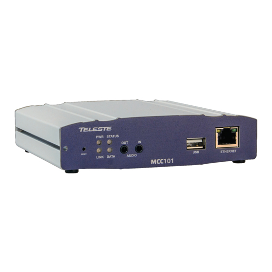
Page 7: Part Names And Functions
LEDs Display power On/Off condition, Link, Status and data Audio In, Out Audio Input and Output, for 3,5 mm stereo jack USB port for external recording purposes LAN (Ethernet) 100/10Base-T Ethernet interface, RJ-45 MCC101 User manual 1. Introduction • 3... -
Page 8: Rear View
RS-422 and RS-485 protocol, screw terminal block Serial Port 1 (COM1) for PTZ control and etc. Support RS-232 (Com1) RS-232 protocol, screw terminal block VIDEO OUT Video output, BNC VIDEO IN Video input, BNC MCC101 User manual 4 • 1. Introduction... -
Page 9: System Connections
System Connections MCC101 operates as one of the two modes; as Encoder or Decoder. MCC101 units can be connected in either 1-to-1 fashion where one encoder is connected one decoder or 1-to-many fashion where one encoder is connected to many decoders. - Page 10 In this arrangement, video and audio can be retransmitted from a center to another center. The arrangement is useful when the network bandwidth at the site is limited while there is more than one center wanting to monitor the site. MCC101 User manual 6 • 1. Introduction...
- Page 11 Video Management System is a server based remote monitoring program to access multiple encoders for real-time monitoring or control of the encoders and connected cameras. A typical integration to VMS system is done via OnVIF interface. MCC101 User manual 1. Introduction • 7...
-
Page 12: Installation
Connect sensor and alarm devices to corresponding terminals accordingly. Connecting Power After confirming the proper power source, connect the mains adaptor to the AC line and connect the 12VDC connector to the MCC unit. MCC101 User manual 8 • 2. Installation... - Page 13 These LEDs show that the Decoder has started without connection to an encoder. Once an encoder is connected, the color of “LINK” LED will be turned to green. “DATA” LED will blink while video or audio data transmissions is detected. MCC101 User manual 2. Installation • 9...
- Page 14 Connected to a remote system LINK Red blinking Decoder only: trying to connect to an Encoder Illegal connection Orange (unsupported combination of system modes) Green Data transmission in progress Data loss DATA No data transmission MCC101 User manual 10 • 2. Installation...
-
Page 15: System Operation
3. System Operation Remote Video Monitoring There are two ways to monitor video when the center system and MCC101 are connected. In order for a proper operation, an IP address must be set accordingly. Default ID: admin Default Password: 1234... - Page 16 Video Monitoring using Internet Explorer If MCC101’s IP address in entered on the Internet Explorer, the system will ask for confirmation to install an Active-X control (Teleste ActiveX Control, Publisher is Teleste Corporation). Once authorized, the Internet Explorer will start to display video images from the encoder as shown below.
- Page 17 Clear: Delete the selected preset entry. Sensor Input Display the status of the sensor in real time. This camera supports one sensor input. When the sensor of the camera is working, the sensor light turns red. MCC101 User manual 3. System Operation • 13...
- Page 18 Set the number of video frames to be buffered before being displayed on web browser. Larger value results in smoother video by sacrificing the latency. A setting of 10 ~ 15 frames can be used generally for most situations. MCC101 User manual 14 • 3. System Operation...
-
Page 19: Initialization Of Ip Address
3. Once the system reboots, IP address will be set to the system default as below. • IP mode Fixed IP • IP address 192.168.10.100 • Subnet mask 255.255.255.0 • Gateway 192.168.10.1 • Base port 2222 • HTTP port MCC101 User manual 3. System Operation • 15... -
Page 20: Remote Configuration
The configurations are grouped into 10 categories: System, Video, Audio, Network, Serial, Event, PTZ, Record, User and Camera. Any configuration changes are not applied until Apply button is pressed. Leaving the page without pressing Apply button, any changes in the page will be discarded. MCC101 User manual 16 • 4. Remote Configuration... -
Page 21: System Configuration
System Configuration MCC101 User manual 4. Remote Configuration • 17... - Page 22 2. Press Firmware Upgrade button to start to upgrade. 3. Messages for showing status (downloading / upgrading) will be displayed. 4. The camera will reboot automatically after completing upgrade. Do not turn the camera off during upgrading MCC101 User manual 18 • 4. Remote Configuration...
- Page 23 By convention, time zones compute their local time as an offset from UTC (Coordinated Universal Time). In casual use, GMT (Greenwich Mean Time) can be considered equivalent to UTC. Local time is UTC plus the current time zone offset for the considered location. MCC101 User manual 4. Remote Configuration • 19...
-
Page 24: Factory Reset
Do not press the Reboot button unless the server needs a reboot. Factory Reset All settings including user accounts and logs are cleared. Factory Reset except network settings All the settings except for current network settings are changed to default values. MCC101 User manual 20 • 4. Remote Configuration... -
Page 25: Video Configuration
Video Configuration MCC101 User manual 4. Remote Configuration • 21... - Page 26 It is preferred when constant video quality is required and network bandwidth is enough for delivering the stream of highly varying bitrate. MCC101 User manual 22 • 4. Remote Configuration...
- Page 27 Select H.264 or MJPEG for the secondary streaming. In case of H.264, either Bitrate mode or Quality mode can be selected for Preference mode in. On the other hand, MJPEG supports Quality mode only. MCC101 User manual 4. Remote Configuration • 23...
- Page 28 System ID and/or server time can be display over the video window in Internet Explorer. Each item can be turn on or off separately, and position also can be configured. This information is displayed after the video is decompressed. MCC101 User manual 24 • 4. Remote Configuration...
- Page 29 Eliminates color interference in very dense graphic patterns. Also improves color separation and image sharpness. 3D Noise Reduction Achieves up to 38% data rate reduction Sharper image details and less visible noise Requires No additional CPU processing power MCC101 User manual 4. Remote Configuration • 25...
- Page 30 De-mist Mode Designed for particle-degraded image conditions; mist, fog, smoke, rain, snow, dust storm, hail, undersea, etc. Adaptively analyzes and restores contrast and color information buried in pale and washed-out images. MCC101 User manual 26 • 4. Remote Configuration...
-
Page 31: Audio Configuration
Note that when camera is connected to a decoder, the decoder’s audio algorithm should be set identically to transmit audio properly. Mode Select audio operation mode: Mode Action No operation Tx - Only Transmit only Rx - Only Receive only Tx & Rx Transmit and Receive MCC101 User manual 4. Remote Configuration • 27... -
Page 32: Input Gain
Configure the audio source to be played on audio output port. Decoded Audio: Audio stream from client is played. Loopback: Audio data from audio input port is loop-backed to the audio output port. MCC101 User manual 28 • 4. Remote Configuration... -
Page 33: Network Configuration
Network Configuration MCC101 User manual 4. Remote Configuration • 29... - Page 34 DNS queries. That server, called a name server, will hold a list of all the IP addresses within its network, plus a cache of IP addresses for recently accessed computers outside the network. MCC101 User manual 30 • 4. Remote Configuration...
- Page 35 By setting UPNP to ON, it allows the discovery by the client according to UPNP (Universal Plug and Play) protocol. Zeroconf By setting Zeroconf to ON, it allows the discovery by the client according to Zeroconf protocol. MCC101 User manual 4. Remote Configuration • 31...
- Page 36 User Name: Enter the User name that will be used as session name in the SDP file. File Name: Enter the file name that will be used as the name of the SDP file. Then, it can be accessed through http://ServerAddress/filename MCC101 User manual 32 • 4. Remote Configuration...
- Page 37 For example, a router could send a message if one of its redundant power supplies fails or a printer could send an SNMP trap when it is out of paper. MCC101 User manual 4. Remote Configuration • 33...
- Page 38 IP will be registered on DDNS server. In DHCP mode, dynamically assigned IP will be registered on DDNS server. Normally Check IP Disable should be unchecked in order to obtain public IP in the network. MCC101 User manual 34 • 4. Remote Configuration...
- Page 39 MAC Address: Display the MAC address of the camera. In case the camera is registered at DDNS server, the MAC address is used in DDNS registration. Connecting: Client IP Addresses that are currently connected to system are listed. (1) Indicates. MCC101 User manual 4. Remote Configuration • 35...
-
Page 40: Serial Configuration
Serial Configuration MCC101 User manual 36 • 4. Remote Configuration... -
Page 41: Serial Port Configuration
The ID value range can be between 0 and 255. PTZ Port: Select the serial port used for PTZ camera control. Sensor Type There are two sensor input ports on MCC101. Each of the sensor ports can be configured to the following. Function Operation Not used. - Page 42 Click desired “Cell” to set schedule. Click desired “Time Line or Date Line” to set schedule. To set cells in the schedule, click below “Empty Cell”. MCC101 User manual 38 • 4. Remote Configuration...
-
Page 43: Event Configuration
Event Configuration MCC101 User manual 4. Remote Configuration • 39... - Page 44 Set the duration of alarm or beep activation in case of an event. If it is set to continuous, it will be in active state until the operator resets it manually. MCC101 User manual 40 • 4. Remote Configuration...
- Page 45 This error happens often when the server SMTP server rejected the mail authenticates according to its own rule. For example, IP addresses of a specific range or addressed of a specific suffix are allowed. MCC101 User manual 4. Remote Configuration • 41...
- Page 46 The duration of video clip can be configured with Pre-Event Time and Post-Event Time in Event Record section. Number of Frame: Enter frame number of JPEG Capture (from 1 to 10). MCC101 User manual 42 • 4. Remote Configuration...
- Page 47 FTP server can be full. Failed to delete the test file. The user of the ID doesn’t have Failed to erase file the privilege for file deletion. MCC101 User manual 4. Remote Configuration • 43...
-
Page 48: Preset Configuration
Preset Configuration Preset Select preset # and insert the name of preset. Set camera position for the preset and press Save List button. MCC101 User manual 44 • 4. Remote Configuration... -
Page 49: Record Configuration
Record Configuration MCC101 User manual 4. Remote Configuration • 45... - Page 50 Disk is detached during operation or there is damage on the file Disk removed or in system. If it happens while disk is connected, it is recommended abnormal state to format the disk. MCC101 User manual 46 • 4. Remote Configuration...
- Page 51 Specify the time of the data in the disk from which Backup to FTP Disk is performed. This time is changed automatically as the backup to FTP server goes. So it is useful to check current backup status. It is valid only when Automatically Backup to FTP is used. MCC101 User manual 4. Remote Configuration • 47...
- Page 52 VMS/NVR) etc. When there are multiple clients and one of the client is disconnected, this doesn’t happen. Event Type: Records when an event configured in Event Type setting happens. Checking status of recording Recording status can be checked on the main view page. Recording status MCC101 User manual 48 • 4. Remote Configuration...
- Page 53 First, choose the date for search and the list of AVI files will be shown. The file name shows the date and time: “Date Begin Time End Time.avi” Press Root to move back to the page with date list. MCC101 User manual 4. Remote Configuration • 49...
- Page 54 If you press Open in the dialog, the file will be downloaded and played automatically with Media Player. Another connection through web is disabled during downloading and it is also not allowed to download two AVI files at the same time. MCC101 User manual 50 • 4. Remote Configuration...
- Page 55 If you want to delete recorded files, select the files by checking the item in front of each file and press Delete button. Press Delete button It is possible to delete multiple files at once. MCC101 User manual 4. Remote Configuration • 51...
-
Page 56: User Configuration
Live viewing and PTZ control Guest Live viewing only Add User Press Add button. The following window will appear. Enter User ID and password (Up to 15 characters) and select Privilege Level. MCC101 User manual 52 • 4. Remote Configuration... - Page 57 Skip Login provides for convenient access to the server when authentication is not required. When Skip Login is set to Enable, login step is skipped. The privilege level after login in this way is determined by the setting of Privilege Level after Login Skipped. MCC101 User manual 4. Remote Configuration • 53...
-
Page 58: Decoder Configuration
5. Decoder Configuration Decoder Configuration is slightly different from Encoder Configuration. Different configurations for the encoder will be explained in Decoder Configuration. System Configuration MCC101 User manual 54 • 5. Decoder Configuration... -
Page 59: Video Configuration
Video Configuration Output Format Regardless input resolution of Encoder or IP camera, Decoder system of MCC101 can display video format. Buffering You can store maximum 30 decoded frames temporarily by using buffering before displaying the frames. Displaying stored frames is smoother than displaying in real time. However, displaying stored frames causes delay because of process of buffering. -
Page 60: Network Configuration
Network Configuration Network page of Decoder has a section for specifying the remote system to connect and the other functions are same as Network Configuration of Encoder MCC101 User manual 56 • 5. Decoder Configuration... - Page 61 SS IP address: IP address of Streaming server. SS port: Enter Port number that is set when registering Streaming server. SS ID: Enter Streaming Server ID. SS password: Enter Streaming Server Password. MCC101 User manual 5. Decoder Configuration • 57...
-
Page 62: Event Configuration
Configure the actions when the sensor 1 or 2 is activated. Multiple actions can be set for a single event. On Video Loss Configure the actions when video input signal is lost. Multiple actions can be set for a single event. MCC101 User manual 58 • 5. Decoder Configuration... -
Page 63: Display Configuration
Select from Video, Audio and Serial to be indicated by Data LED. When there is the selected data (Video or Audio or Serial) communication between the encoder and the decoder, Data LED will indicate the status. MCC101 User manual 5. Decoder Configuration • 59... -
Page 64: Appendix
6. Appendix Appendix A: Sensor and Alarm Port Sensor Port Terminal Type Voltage Rating: 150VAC Current Rating: 2A Color: Red Sensor Signal Input Type NO Contact Signals Connection to External Device MCC101 User manual 60 • 6. Appendix... - Page 65 Voltage Rating: 150VAC Current Rating: 2A Relay Type Contact Rating: 1A 30VDC Switching Power: Max 30W 62.5VA Switching Voltage: Max 60VDC Alarm Signal Output Type NO/NC Contact Signals Connection to External Device MCC101 User manual 6. Appendix • 61...
- Page 66 Pin Description Pin No. Pin Name Description RS422 RX- RS422 RX+ RS422 TX- or RS485 TRX- (It is selectable by S/W Setup) RS422 TX+ or RS485 TRX+ (It is selectable by S/W Setup) MCC101 User manual 62 • 6. Appendix...
- Page 67 This document is protected by copyright laws. Unauthorized distribution or reproduction of this document is strictly prohibited. Teleste reserves the right to make changes to any of the products described in this document without notice and all specifications are subject to change without notice. Current product specifications are stated in the latest versions of detailed product specifications.
- Page 68 MCC101 User manual 64 •...
Need help?
Do you have a question about the MCC101 and is the answer not in the manual?
Questions and answers