
Related Manuals for Teleste EASI


Summary of Contents for Teleste EASI
-
Page 1: User Manual
™ EASI IP Series User Manual IPE MPEG-2 encoder & IPD MPEG2 decoder IPE & IPD user manual, 59300103, rev002... -
Page 2: Table Of Contents
Contents Introduction ..................................1 General ..................................1 Software version ..............................1 Features ................................... 1 Installation ..................................2 Quick instructions ..............................2 IPE3 & IPD3 mechanical connections & Models ..................... 3 IPE1 & IPD1 mechanical connections & Models ..................... 4 Connections ..................................5 General .................................. -
Page 3: Introduction
Stand-alone or rack mount CAT5, multimode or siglemode devices with one video, two audio and three data channels, in-band management Welcome, and thank you for purchasing Teleste’s EASI™ Products. General IPE is a fi eld hardened stand-alone (IPE3) or a rack mount (IPE1) video, audio &... -
Page 4: Installation
Installation Quick Instructions Install the fi eld hardened stand-alone IPE3/IPD3 device (1U high, 19” wide) to the installation cabinet. A 12 V supply voltage is provided by a CPS24x mains adapter. Install the rack mount IPE1/IPD1 device into a DVX002- installation frame equipped with a DVP power supply. -
Page 5: Ipe3 & Ipd3 Mechanical Connections & Models
IPE3 & IPD3 mechanical connections Composite (CVBS) video input / output (IPE3 / IPD3), BNC female connector. S-video (Y/C) input / output (IPE3 / IPD3), 4 pin min-DIN female connector. 3 . 2 audio inputs / outputs (IPE3 / IPD3), RJ-45 female connector. -
Page 6: Ipe1 & Ipd1 Mechanical Connections & Models
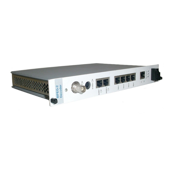
IPE14*XXXA Singlemode Medium Haul (40 km) IPD10*XXXA CAT5 (100 m) IPD12*XXXA Multimode (2 km) IPD13*XXXA Singlemode Short Haul (15 km) Fast Ethernet Fast Ethernet IPD14*XXXA Singlemode Medium Haul (40 km) EASI EASI Picture 4. Picture 5. IPE101A Mpeg-2 IPD101A Mpeg-2 Encoder / connections. -
Page 7: Connections
Connections General All products in EASI™ IP family have the same connection scheme in their connectors. Depending the model, there are Video, S-Video, Audio, Data, Mgmt & Ethernet 100Base-TX/FX connections. Video, audio, data and Ethernet port settings can be confi gured from web user interface (WebUI) or command line interface (CLI). -
Page 8: Data Connections
Data Connections The data connectors (1, 2 & 3) provide one bi-directional data channel (IPE <--> IPD). The data type can be set to RS232, RS422, RS485-2w or RS485-4w. You can confi gure data settings by help of WebUI or CLI. The connector is type RJ-45 female (see picture 8 and table 2 for detailed description). -
Page 9: Mgmt Connection
Management Connection The Mgmt (Management) connector provides one bi-directional data channel (RS232). The Mgmt connection is meant for confi guration and controlling of IPE/IPD devices locally by CLI. Management connection between IPE/IPD devices and e.g. laptop is based on a serial data communication by means of any terminal type program (e.g Windows Hyper Terminal). -
Page 10: Ethernet Connection
Ethernet Connection The Ethernet connector provides 10/100Base-TX or 100Base-FX Ethernet network interface. The connector is type RJ-45 female (CAT5, see picture 10 and table 4 for detailed description) or dual MT-RJ (when optical multimode) or dual LC (when optical singlemode). When the Ethernet connection status is OK, the “C”... -
Page 11: Changing The Settings Of Ipe/Ipd Devices
IPE/IPD device with help of web user interface (WebUI) or command line interface (CLI). Web User Interface (WebUI) Teleste’s WebUI provides an user friendly way to confi gure and manage IPE/IPD device. WebUI session can be accessed using Internet browser such as Internet Explorer. See next page for detailed description. -
Page 12: Web User Interface (Webui)
Web User Interface (WebUI) Introduction This chapter tells how to confi gure the settings using web user interface. General The IPE encoders and the IPD decoders are fully controllable with the Web User Interface (WebUI). System Requirements: The PC equipped with an Ethernet Network card and an Internet browser installed. -
Page 13: Starting
Starting To create the WebUI session to the device, fi rst enter device’s IP address into the web browser’s address. Encoder’s default factory IP address is 10.9.96.10 and Decoder’s default factory IP address is 10.9.96.20. The following Web User Interface’s start page will appear on the screen (picture 11). -
Page 14: General Information - Page
General General information Click heading “General Information” under the General menu on the left column. General information / device information window appears on the right side of page (picture 13 & 14). On this page you can see device’s general settings and change device’s hostname. -
Page 15: Network Confi Guration - Page
Network confi guration Click heading “Network Confi g” under the General menu on the left column. Network confi guration / ethernet information window appears on the right side of page (picture 15 & 16). On this page you can see and change device’s Ethernet network settings. -
Page 16: Video Confi Guration - Page
Video Video confi guration Click heading “Confi guration” under the Video menu on the left column. Video confi guration / video stream window appears on the right side of page (pictures 17 & 18). On this page you can modify device’s video interface confi... -
Page 17: Video Management - Page
Video management Click heading “Video Management” under the Video menu on the left column of page. Video management / quality of service (when IPE) / unicast video fi ltering (when IPD) window appears on the right side of page (pictures 19 & 20). On this page you can modify device’s video Qos and unicast video settings: IPE:... -
Page 18: Sap Management - Page
SAP management Click heading “SAP Management” under the Video menu on the left column of page. Sap management / session announcement protocol window appears on the right side of page (picture 21 & 22). On this page you can modify device’s session announcement protocol settings: SAP Service: Service enabled / disabled Multicast Group: SAP advertisements... -
Page 19: Video Statistics - Page
Video statistics (only in IPD) Click heading “Statistics” under the Video menu on the left column. Video statistics / transport stream window appears on the right side of page (picture 23). On this page you can see IPD device’s video stream settings. Video state: Display received video state (active/waiting/inactive/error) Detected bitrate: Display received... -
Page 20: Change Password / User Management - Page
Administration Change password To change the password, fi rst click heading “Change Password” under the Administration menu on the left column. Administration / change password window appears on the right side of page (picture 24). On this page you can change your username and password. -
Page 21: Services - Page
To change the user password First select user from users list by ticking the checkbox before the username. Write new password to the box after button. Click button to activate the new password. Note! Use only characters and numbers. Do not use special characters! To remove the user, fi... -
Page 22: Data Channel
Data ports Data channel confi guration Click heading Data channel 1, 2 or 3 under the Ports menu on the left column. Data channel confi guration / data channel 1, 2 or 3 window appears on the right side of page (e.g. picture 28 for data channel 1). On these pages you can change data channel 1...3 settings. -
Page 23: Data Channel Statistics - Page
Data channel statistics Click heading “Statistics” under the Ports menu on the left column. Data channel 1, 2 and 3 statistics window appears on the right side of page (picture 29). Rx bytes: Number of bytes received since the last counter reset (start-up). Tx bytes: Number of bytes transmitted since the last counter reset (start-up). -
Page 24: Command Line Interface - Cli
1. Start the Windows Hyper Terminal program (in Windows by choosing -> Start/Programs/Accessories/Communications/ Hyper Terminal). Wait until the following “Connection Description” window appears on the screen (see picture 30). 2. Enter a name for connection, e.g. “EASI ™ IP Management” and click OK button to continue. -
Page 25: Connection Methods - Telnet
Connection methods - Telnet 1. Start the Run utility program (in Windows by choosing -> Start/Run...). Wait until the following “Run” window appears on the screen (see picture 34). 2. Write Telnet and click button to continue. Picture 34. Run utility program view. The following “Telnet.exe”... -
Page 26: How To Use The Cli
How to use the CLI CLI levels CLI consists of several levels. You can move from one level to other by step by step.(See picture 37 and table 10 for detailed description). To execute the command, press enter after typing command. Note! All letters must be typed as lowercase. -
Page 27: Detailed Descriptions Of Commands
Detailed descriptions of commands Disable level When the CLI session has been established to the IPE/IPD device, fi rst the user enters on CLI’s disable level --> “ ” text appears on the screen. IPx> Available information on disable level is e.g. device hardware version and serial number. -
Page 28: Enable Level
Enable level On enable level the user is able to view device settings (and on admin rights it is also possible to update the device software version). Enable level is activated by entering command enable (or en) on disable level -->... -
Page 29: Confi G Level
Confi g level On confi g level the user is able to change device settings such as hostname, username and default IP gateway. Confi g level is activated by entering command confi gure terminal (or c t) on enable level --> “IPx(config)#” text appears on the screen. -
Page 30: Confi G-If Level For Data Channels
Confi g-if level for data channels On confi g-if level for data channel the user is able to change device’s data interface settings. Confi g-if level for data channel is activated by entering command interface datachannel [1/2/3] (or in d 1/2/3) on confi g level --> “IPx(config-if)#” text appears on the screen. -
Page 31: Confi G-If Level For Fast Ethernet
Confi g-if level for Fast Ethernet On confi g-if level for Fast Ethernet the user is able to change device’s Ethernet interface settings. Confi g-if level for Fast Ethernet is activated by entering command interface fastethernet (or in f) on confi g level --> “IPx(config-if)#” text appears on the screen. -
Page 32: Confi G-Sap Level
Confi g-sap level On confi g-sap level the user is able to change device’s sap (session announcement protocol) settings. Confi g-sap level is activated by entering command video sap (or v s) on confi g level --> “IPx(config-sap)#” text appears on the screen. -
Page 33: Confi G-Ts Level
Confi g-ts level On confi g-ts level the user is able to change device’s video interface settings. Confi g-ts level is activated by entering command video transport-stream (or v t) on confi g level --> “IPx(config-ts)#” text appears on the screen. Entering ? displays a list of commands for confi... -
Page 34: Confi G-Fi Lter Level
Confi g-fi lter level On confi g-fi lter level the user is able to change IPD device’s unicast video fi ltering settings. Confi g-fi lter level is activated by entering command video unicast-fi ltering (or v u)on confi g level --> “IPx(config-filter)#” text appears on the screen. -
Page 35: Confi G-Line Level
Confi g-line level On confi g-line level the user is able to change terminal view settings. Confi g-line level is activated by entering command line-console (or l c) on confi g level --> “IPx(config-line)#” text appears on the screen. Entering ? displays a list of commands for confi... -
Page 36: Glossary
Glossary Bandwidth Ethernet The width of a communication channel, measured Specifi ed in a standard, IEEE 802.3. 10BASE-T as frequency (hertz) or bits per second (bps). Ethernet systems provide transmission speeds up to 10 Mbps. Fast Ethernet or 100BASE-T provides Baudrate transmission speeds up to 100 megabits per second The speed of information being transmitted across a... - Page 37 Half Duplex Local Area Network (LAN) The ability to transmit and receive signals in both A local area network is generally a private network. directions, but only in one direction at a time It is under the control of the owner and used by a set of related individuals and/or workgroups, typically Host within a single building or over a group of neighbor-...
- Page 38 Metropolitan Area Network (MAN) MTU (Maximum Transmission Device) A network that interconnects users with computer The largest possible device of data that can be resources in a geographic area or region larger than transmitted between a source and a destination. that covered by even a large local area network Note that a distinction must be made between the (LAN) but smaller than the area covered by a wide...
- Page 39 Network Layer: OSI Layer 3 PMT (Program Map Tables) Provides upper layers with independence from the The tables in PAT that point to video, audio, and data data transmission and switching technologies used content of a transport stream. to connect systems; responsible for establishing, PCR (Program Clock Reference) maintaining, and terminating connections.
- Page 40 Router Scalability On the Internet, a router is a device or, in some A characteristic of MPEG2 that provides for multiple cases, software in a computer, that determines quality levels by providing layers of video data. the next network point to which a packet should be Multiple layers of data allow a complex decoder to forwarded toward its destination.
- Page 41 Computer terminal; a device that is able to communi- er-Decoder), network access equipment, network, cate (usually asynchronously) with a host computer. and audio system, e.g. EASI™ BLUEbox devices. Time to Live (TTL) VLAN (Virtual LAN) A value in an Internet Protocol (IP) packet that tells a Network confi...
-
Page 42: Copyright Acknowledgements
This obligation applies to the equipment put on the market in EU after 13 August 2005. Teleste devices which belong to the scope of the directive have been marked with the separate collection symbol shown below. The marking is according to the standard EN 50419. -
Page 43: Technical Specifi Cations
Technical Specifi cations Technical Specifi cations Parameter Specifi cation Note Optical m/m 1310 nm 2 km s/m 1310 nm 15 / 40 km Ethernet Number of ports half/full duplex Standard 10/100Base-TX CAT-5 100Base-FX m/m & s/m fi bre Protocols Video/Audio/Data UDP, IP, TCP/IP Management SNMP, HTTP, Telnet, DHCP, SAP... - Page 44 www.teleste.com...
Need help?
Do you have a question about the EASI and is the answer not in the manual?
Questions and answers