
Subscribe to Our Youtube Channel
Related Manuals for Teleste EASI INE101


Summary of Contents for Teleste EASI INE101
-
Page 1: User Manual
EASI ATM Series User Manual INE1x1 MPEG-2 Encoder INE1x1 User Manual, 59300036, rev001... -
Page 2: Table Of Contents
Contents Introduction ......................1 General............................1 Features ............................1 Monitoring Functions ........................1 Models............................1 Installation........................2 Quick Instructions.........................2 Mechanical Installation .........................3 Mechanical Connections ......................3 Front Panel Leds ..........................3 Connections ......................4 General............................4 S-Video Connection ........................4 ATM Connection ...........................4 How to Confi gure the INE1x1 MPEG-2 Encoder ...........5 General............................5 System Requirements ........................5 Hardware Requirements ......................5... -
Page 3: Introduction
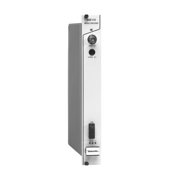
INTRODUCTION INE1x1 Rack Mount CAT5, Multimode or Singlemode Encoder Unit with one Video, In-Band Management General INE1x1 is a rack mount one channel video Encoder unit for EASI surveillance applications (see list of models below). This unit provides a transparent link of PAL or NTSC video signal. -
Page 4: Installation
INSTALLATION Quick Instructions Install the unit into a DVX002-installation frame equipped with a DVP power supply. The rack must have a unique bus address assigned. Switch on the system power and see that the “M”, “C” and “V” -indicators on the front panel of the unit are lit. The “M”... -
Page 5: Mechanical Installation
Mechanical Installation INE101 INE1x1 is installed into a DVX002 installation frame equipped MPEG with a specifi ed DVX bus address (refer to the frame ENCODER installation instructions) and a DVP412 (115 V AC) or a DVP432 (230 V AC) power supply. The unit can be installed into any frame position, however the power supply is normally placed in the left-hand side of the frame. -
Page 6: Connections
CONNECTIONS General All products in EASI family have the same connection scheme in their connectors. Depending the model in question, there is video, S-video, audio, data, 10Base-T, ATM and control bus (DVX bus) connection in the unit. Video Connection The video (input) connector in use is either a BNC male Picture 2. -
Page 7: How To Confi Gure The Ine1X1 Mpeg-2 Encoder
HOW TO CONFIGURE THE INE1x1 MPEG-2 ENCODER General This chapter tells how with help of the Commander software you can confi gure the settings of INE1x1 Encoder and introduce the functions of the Confi guration Displays. The Confi guration Displays are a part of the Commander software application. System Requirements Hardware requirements - The PC, minimum requirements: Pentium II prosessor, display... -
Page 8: Establishing A Data Connection
Establishing a Data Connection 1. Connect a DVX021 connection cable between the COM port of your PC and the Control Bus connector of the INE1x1 unit. 2. Install the Commander and Viewer softwares by running autorun.exe (if installation doesn’t start automatically). The following window appears on the screen (picture 4). -
Page 9: Starting Catvisor Tm Commander
Starting CATVisor Commander After installing the softwares launch Commander. When the program has started the following “Untitled Commander” window appears on the screen (picture 6). Picture 6. Commander’s main view. Commander is now running, but not yet communicating with INE1x1. Create the connection to the INE1x1 by choosing --> File/New or Connection/Add New commands from the pull- down menus. -
Page 10: Catvisor Tm Commander - Connected Window
CATVisor Commander - Connected Window Pull-Down menus Toolbar Element Tree Directory Element Window Element Tree Window Status Bar Picture 7. Event Window Commander Main View, connected window. The Commander main view consist of the Element Tree Window, Element Window, Event Window, Pull Down Menus, the Tool Bar and the Status Bar. -
Page 11: Confi Guring The Units Using Catvisor
Confi guring the unit using CATVisor Commander Clicking on a specifi c unit in the Element Tree Directory, a Confi guration Display appears on the right side. The Confi guration Display includes all the programmable and monitorable controls and settings of that unit. Headings Confi... -
Page 12: Ine1X1 Mpeg-2 Encoder Confi Guration Display V1.0
INE1x1 MPEG-2 ENCODER CONFIGURATION DISPLAY V1.0 General Commander’s Confi guration Display window consists of several pages. Only one page is completely visible at one time. You can activate a page simply by clicking the page’s heading (see pictures 8 and 9). Picture 9. - Page 13 If a data fi eld or box has a grey background, it contains read- only information that cannot be edited. Red, yellow and green backgrounds of data fi elds or boxes indicate alarms, warnings and notifi cations related to the settings or values in them. The new settings are saved in the non-volatile memory of the confi...
-
Page 14: Status Page
Status Page Picture 10. Commander’s “Status” page view. The Status Page lists information messages about the unit’s present status. The EASI Confi gurer divides these messages into three different categories according to severity and uses Status Flags to make them more noticeable: - Alarm messages are indicated with red fl... - Page 15 Messages are divided into four groups: - Alarms concerning BIOS. - Alarms concerning application. - Warnings concerning application. - Notifi cations concerning application. Alarm In case the unit senses an alarm a red Alarm fl ag appears in the Commander’s Element Directory Window. The description of this alarm can be read from the Commander’s Status Page.
-
Page 16: Properties Page
Properties Page Picture 11. Commander’s “Properties” page view. The Properties page displays information of the unit’s hardware and software.The unit’s name which you can see on the Element Tree Window and Element Window can be set on this page. INE1x1 Series User Manual rev001... -
Page 17: Module Page
Module Page Picture 12. Commander’s “Module” page view. The Module page is only enabled when confi guring standalone versions (e.g. INE2x2 of EASI MPEG-2 Encoders). INE1x1 Series User Manual rev001... -
Page 18: Video Page
Video Page Picture 13. Commander’s “Video” page view. On the Video page you can confi gure the physical camera interface. Video Format The Encoder has support PAL and NTSC video standards. This setting should match with the video connected to the input of the Encoder. -
Page 19: Mpeg Page
MPEG Page Picture 14. Commander’s “MPEG” page view. The MPEG page is used for confi guring MPEG compression parameters. In MPEG compression PID stands for Program Identifi er and PMT is Program Map Table. PID is an individual identifi er for separate MPEG data streams and therefore the audio,video and PMT. - Page 20 Stream Speed frame This selection allows you to limit the maximum encoded bitrate. It becomes worthy when designing and managing large networks with limited bandwidth. This value is a tradeoff between bandwidth and sharpness of the moving objects in the video. The higher the value, the sharper are moving details. In surveillance applications setting 6.75 Mbps gives an excellent picture in most cases.
-
Page 21: Data Page
Data Page Picture 15. Commander’s “Data” page view. Data features are not available in this model. INE1x1 Series User Manual rev001... -
Page 22: Atm Page
ATM Page Picture 16. Commander’s “ATM” page view. The ATM page displays ATM/SDH (Asychronous Transfer Mode / Synchronous Digital Hierarchy) connection status and allows you to set all necessary VPI’s and VCI’s. VPI is the Virtual Path Identifi er. VCI is the Virtual Channel Identifi er. VPI is selectable between 1…255 and VCI between 1…65500. - Page 23 Data Filter checkboxes Not available in this model. Stream Rate frame This frame indicates the transmitted and received ATM bitrate in kbps. AU-4 Pointer checkbox For SDH network operation the AU-4 pointer can be enabled or disabled. The default setting is disabled (Sonet operation). SDH frame This frame displays the following fl...
-
Page 24: In-Band Management Page
In-Band Management Page ATM Interface settings IP Route settings Picture 17. Commander’s “In-Band Management” page view. EASI Encoder confi guration pages are accessible also over the ATM network by utilising In-Band Management. This feature allows the user to confi gure all Encoders and Decoders in the network from one location. - Page 25 How to modify ATM Interface Select the ATM interface from the Interface list (see picture 17 and click modify to modify ATM interface. The following “Modify Interface” window appears on the screen (see picture 18). Set required values to IP address, Subnet mask and Picture 18.
-
Page 26: Snmp Page
SNMP Page Picture 20. Commander’s “SNMP” page view. The SNMP page is not used in normal operation (for factory use only). INE1x1 Series User Manual rev001... -
Page 27: Constructing Easi Tm Networks
Information in this document is subject to change without notice and does not represent a commitment on the part of Teleste Corporation. The software as described in this document is supplied only under a licence agreement. The software may be used or copied only in accordance with the terms of the agreement.
Need help?
Do you have a question about the EASI INE101 and is the answer not in the manual?
Questions and answers