
Subscribe to Our Youtube Channel
Related Manuals for Teleste MCC201


Summary of Contents for Teleste MCC201
-
Page 1: User Manual
User manual MCC201 / MCC201H H.264 Encoder/decoder This manual provides information on installation setup and operation of the video server, as well as troubleshooting tips. MCC201/MCC201H User manual, 59300507, rev002... -
Page 3: Table Of Contents
PTZ Configuration ......................42 Record Configuration ......................43 5. Decoder Configuration ......................51 System Configuration ......................51 Network Configuration ......................53 Event Configuration ......................55 Display Configuration ......................56 6. Appendix ..........................57 Legal Declarations ........................60 • I MCC201/MCC201H User manual... -
Page 5: Introduction
MCC201 is a video and audio transmission system that provides broadcast quality audio and video, based on IP networking. MCC201 can operate either as an Encoder or as a Decoder, the desired mode is user- selectable. MCC201H is a model variant which has all other functions available except HD-SDI operation. -
Page 6: Product And Accessories
System configuration by web browser (Internet Explorer recommended) High Reliability Reliable embedded system System recovery by watchdog functions Product and Accessories MCC201/MCC201H User Manual Power adapter and Cable (in CD) 2 • 1. Introduction MCC201/MCC201H User manual... -
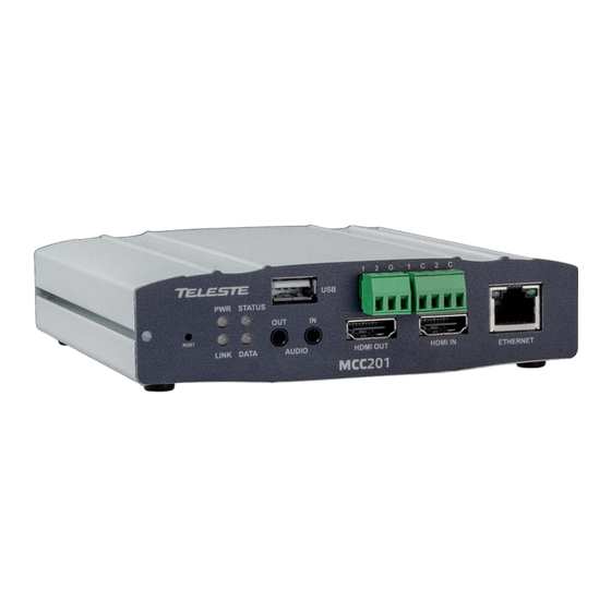
Page 7: Part Names And Functions
USB (2.0) port for any USB device Audio In, Out Audio Input and Output Sensor Sensor Input Alarm Alarm or Relay Output HDMI In, Out HDMI Video Input and Output LAN (Ethernet) 10/100Base-TX electrical Ethernet interface 1. Introduction • 3 MCC201/MCC201H User manual... -
Page 8: Rear View
Serial port for PTZ control and etc. Composite Video Output Composite Out Composite Video Input Composite In HD/SD-SDI Video Output (MCC201H, not in use) HD/SD-SDI Out HD/SD-SDI In HD/SD-SDI Video Input (MCC201H, not in use) 4 • 1. Introduction MCC201/MCC201H User manual... -
Page 9: System Connections
System Connections MCC201 operates as one of two modes; as Encoder or Decoder. MCC201 systems can be connected in either 1-to-1 fashion where one encoder is connected one decoder or 1-to-many fashion where one encoder connected to many decoders. Following chart shows data status of video, audio and serial data on each mode. - Page 10 In this arrangement, video and audio can be retransmitted from a center to another center. The arrangement is useful when the network bandwidth at the site is limited while there is more than one center wanting to monitor the site. 6 • 1. Introduction MCC201/MCC201H User manual...
- Page 11 VMS (Video Management System) is a Windows based remote monitoring program to access multiple encoders for real-time monitoring or control of the encoders and connected cameras. A typical integration to VMS system is done via OnVIF interface. 1. Introduction • 7 MCC201/MCC201H User manual...
-
Page 12: Installation
COM2 port. Connecting Sensor and Alarm Connect sensor and alarm devices to corresponding terminals accordingly. Connecting Power After confirming the power source, connect power adaptor and connect the 12VDC connector to the system. 8 • 2. Installation MCC201/MCC201H User manual... - Page 13 These LEDs show that the Decoder has started without connecting to an encoder. Once an encoder is connected, the color of “LINK” LED will be turned to green and the “DATA” LED will blink as video or audio data transmissions occur. 2. Installation • 9 MCC201/MCC201H User manual...
- Page 14 Connected to a remote system LINK Red blinking Decoder only: trying to connect to an Encoder Illegal connection Orange (unsupported combination of system modes) Green Data transmission in progress Data loss DATA No data transmission 10 • 2. Installation MCC201/MCC201H User manual...
-
Page 15: System Operation
3. System Operation Remote Video Monitoring There are two ways to monitor video when the center system and MCC201 are connected. In order for a proper operation, an IP address must be set accordingly. Default IP Address : http://192.168.10.100 Default ID : admin... -
Page 16: Live View Controls
When the MMC201 or MCC201H is managed by a Windows Explorer browser, shortly after logging the OS will ask permission to install an Active-X component (publisher is Teleste Corporation) to the user´s computer. This plug-in component is needed in order to activate the Live View software video decoder as shown below. - Page 17 Clear: Delete the selected preset entry. Sensor Input Display the status of the sensor in real time. This camera supports one sensor input. When the sensor of the camera is working, the sensor light turns red. 3. System Operation • 13 MCC201/MCC201H User manual...
- Page 18 Set the number of video frames to be buffered before being displayed on web browser. Larger value results in smoother video by sacrificing the latency. A setting of 10 ~ 15 frames can be used generally for most situations. 14 • 3. System Operation MCC201/MCC201H User manual...
-
Page 19: Initialization Of Ip Address
3. Once the device has completed the reboot and has restarted, the default IP address settings are as follows: • IP mode • IP address Fixed IP 192.168.10.100 • Subnet mask • Gateway 255.255.255.0 192.168.10.1 • Base port • HTTP port 2222 3. System Operation • 15 MCC201/MCC201H User manual... -
Page 20: Remote Configuration
The configurations are grouped into 10 categories: System, Video, Audio, Network, Serial, Event, PTZ, Record, User and Camera. Any configuration changes are not applied until Apply button is pressed. Leaving the page without pressing Apply button, any changes in the page will be discarded. 16 • 4. Remote Configuration MCC201/MCC201H User manual... -
Page 21: System Configuration
System Configuration 4. Remote Configuration • 17 MCC201/MCC201H User manual... - Page 22 Messages for showing status (downloading / upgrading) will be displayed. The video server will reboot automatically after completing upgrade. Note! Do not switch the power off during the firmware upgrade. Be patient - the process may take several minutes. 18 • 4. Remote Configuration MCC201/MCC201H User manual...
- Page 23 By convention, time zones compute their local time as an offset from UTC (Coordinated Universal Time). In casual use, GMT (Greenwich Mean Time) can be considered equivalent to UTC. Local time is UTC plus the current time zone offset for the considered location. 4. Remote Configuration • 19 MCC201/MCC201H User manual...
-
Page 24: Factory Reset
Do not press the Reboot button unless the server needs a reboot. Factory Reset All settings including user accounts and logs are cleared. Factory Reset except network settings All the settings except for current network settings are changed to default values. 20 • 4. Remote Configuration MCC201/MCC201H User manual... - Page 25 Video Configuration 4. Remote Configuration • 21 MCC201/MCC201H User manual...
- Page 26 Input Format Select the desired video input format according to the video source. When in encoder mode the MCC201 supports analogue composite video (PAL & NTSC) but also digital HDMI and HD-SDI signals. For the digital signals the dropdown menu is containing a selection of supported video resolutions.
- Page 27 Select H.264 or MJPEG for the secondary streaming. Both CBR and VBR modes are available. However the MJPEG is supported only by the VBR mode and hence the video quality level needs to be assigned. 4. Remote Configuration • 23 MCC201/MCC201H User manual...
- Page 28 System ID and/or server time can be display over the video window in Internet Explorer. Each item can be turn on or off separately, and position also can be configured. This information is displayed after the video is decompressed. 24 • 4. Remote Configuration MCC201/MCC201H User manual...
-
Page 29: Output Format
720p60 (1280 x 720) • 1080i60 (1920 x 1080) • 720p50 (1280 x 720) • 1080i50 (1920 x 1080) • 1080i59.94 (1920 x 1080) • 720p59.94 (1280 x 720) • 1080p30 (1920 x 1080) 4. Remote Configuration • 25 MCC201/MCC201H User manual... -
Page 30: Audio Configuration
Select the bitrate between 64Kbps and 128kbps when AAC is selected. The sampling rate is fixed to 8KHz and 32KHz for G.711 and AAC respectively. Note! When two MCC units are connected together (encoder - decoder) the audio settings should be identical. 26 • 4. Remote Configuration MCC201/MCC201H User manual... -
Page 31: Input Gain
Configure the audio source to be played on audio output port. Decoded Audio: Audio stream from client is played. Loopback: Audio data from audio input port is loop-backed to the audio output port. 4. Remote Configuration • 27 MCC201/MCC201H User manual... -
Page 32: Network Configuration
Network Configuration 28 • 4. Remote Configuration MCC201/MCC201H User manual... - Page 33 Enter the designated Ipv6 address. Ipv6 Subnet Prefix Length Enter the bit number of Ipv6 Subnet. Ipv6 Default Gateway Enter the designated Ipv6 gateway. Ipv6 Link Local Display Ipv6 Link Local. 4. Remote Configuration • 29 MCC201/MCC201H User manual...
- Page 34 If RTSP Authentication set to ON, user in the client side is asked to enter User ID and Password. HTTP API Authentication When HTTP API authentication set to ON, HTTP Authentication is asked for all clients which use HTTP API. 30 • 4. Remote Configuration MCC201/MCC201H User manual...
- Page 35 As MPEG-TS itself supports only AAC as the audio algorithm, only video is streamed when audio algorithm is set to G.711. 4. Remote Configuration • 31 MCC201/MCC201H User manual...
- Page 36 IP will be registered on DDNS server. In DHCP mode, dynamically assigned IP will be registered on DDNS server. Normally Check IP Disable should be unchecked in order to obtain public IP in the network. 32 • 4. Remote Configuration MCC201/MCC201H User manual...
- Page 37 MAC Address: Display the MAC address of the video server. In case the video server is registered at DDNS server, the MAC address is used in DDNS registration. Connecting: Client IP Addresses that are currently connected to system are listed. 4. Remote Configuration • 33 MCC201/MCC201H User manual...
-
Page 38: Serial Configuration
Serial Configuration 34 • 4. Remote Configuration MCC201/MCC201H User manual... -
Page 39: Serial Port Configuration
The ID value range can be between 0 and 255. PTZ Port: Select the serial port used for PTZ camera control. Sensor Type There are two sensor input ports on MCC201. Each of the sensor ports can be configured to the following. Function Operation Not used. - Page 40 Click desired “Cell” to set schedule. Click desired “Time Line or Date Line” to set schedule. To set cells in the schedule, click below “Empty Cell”. 36 • 4. Remote Configuration MCC201/MCC201H User manual...
-
Page 41: Event Configuration
Event Configuration 4. Remote Configuration • 37 MCC201/MCC201H User manual... - Page 42 Set the duration of alarm or beep activation in case of an event. If it is set to continuous, it will be in active state until the operator resets it manually. 38 • 4. Remote Configuration MCC201/MCC201H User manual...
- Page 43 This error happens often when the server SMTP server rejected the mail authenticates according to its own rule. For example, IP addresses of a specific range or addressed of a specific suffix are allowed. 4. Remote Configuration • 39 MCC201/MCC201H User manual...
- Page 44 The duration of video clip can be configured with Pre-Event Time and Post-Event Time in Event Record section. Number of Frame: Enter frame number of JPEG Capture (from 1 to 10). 40 • 4. Remote Configuration MCC201/MCC201H User manual...
- Page 45 FTP server can be full. Failed to delete the test file. The user of the ID doesn’t have Failed to erase file the privilege for file deletion. 4. Remote Configuration • 41 MCC201/MCC201H User manual...
-
Page 46: Ptz Configuration
Preset Select preset # and insert the name of preset. Set camera position for the preset and press Save Label button. 42 • 4. Remote Configuration MCC201/MCC201H User manual... -
Page 47: Record Configuration
Record Configuration 4. Remote Configuration • 43 MCC201/MCC201H User manual... - Page 48 Disk is detached during operation or there is damage on the file Disk removed or in system. If it happens while disk is connected, it is recommended abnormal state to format the disk. 44 • 4. Remote Configuration MCC201/MCC201H User manual...
- Page 49 VMS/NVR) etc. When there are multiple clients and one of the client is disconnected, this doesn’t happen. Event Type: Records when an event configured in Event Type setting happens. Checking status of recording Recording status can be checked on the main view page. Recording status 4. Remote Configuration • 45 MCC201/MCC201H User manual...
- Page 50 First, choose the date for search and the list of AVI files will be shown. The file name shows the date and time: “Date Begin Time End Time.avi” Press Root to move back to the page with date list. 46 • 4. Remote Configuration MCC201/MCC201H User manual...
- Page 51 If you press Open in the dialog, the file will be downloaded and played automatically with Media Player. Another connection through web is disabled during downloading and it is also not allowed to download two AVI files at the same time. 4. Remote Configuration • 47 MCC201/MCC201H User manual...
- Page 52 If you want to delete recorded files, select the files by checking the item in front of each file and press Delete button. Press Delete button It is possible to delete multiple files at once. 48 • 4. Remote Configuration MCC201/MCC201H User manual...
-
Page 53: User Configuration
Live viewing and PTZ control Guest Live viewing only Add User Press Add button. The following window will appear. Enter User ID and password (Up to 15 characters) and select Privilege Level. 4. Remote Configuration • 49 MCC201/MCC201H User manual... - Page 54 Skip Login provides for convenient access to the server when authentication is not required. When Skip Login is set to Enable, login step is skipped. The privilege level after login in this way is determined by the setting of Privilege Level after Login Skipped. 50 • 4. Remote Configuration MCC201/MCC201H User manual...
-
Page 55: Decoder Configuration
Note! When turning the operation from an encoder to a decoder requires a selection of the system mode and reboot of the device. Once the Apply button is pressed a windows dialogue will appear to confirm the restart. System Configuration 5. Decoder Configuration • 51 MCC201/MCC201H User manual... - Page 56 You can store maximum 30 decoded frames temporarily by using buffering before displaying the frames. Displaying stored frames is smoother than displaying in real time. However, displaying stored frames causes delay because of process of buffering. 52 • 5. Decoder Configuration MCC201/MCC201H User manual...
-
Page 57: Network Configuration
Network Configuration Network configuration page has a section for specifying the remote system to be connected to (MCC encoder or IP camera). 5. Decoder Configuration • 53 MCC201/MCC201H User manual... - Page 58 SS IP address: IP address of Streaming server. SS port: Enter Port number that is set when registering Streaming server. SS ID: Enter Streaming Server ID. SS password: Enter Streaming Server Password. 54 • 5. Decoder Configuration MCC201/MCC201H User manual...
-
Page 59: Event Configuration
Configure the actions when the sensor 1 or 2 is activated. Multiple actions can be set for a single event. On Video Loss Configure the actions when video input signal is lost. Multiple actions can be set for a single event. 5. Decoder Configuration • 55 MCC201/MCC201H User manual... -
Page 60: Display Configuration
Select from Video, Audio and Serial to be indicated by Data LED. When there is the selected data (Video or Audio or Serial) communication between the encoder and the decoder, Data LED will indicate the status. 56 • 5. Decoder Configuration MCC201/MCC201H User manual... -
Page 61: Appendix
6. Appendix Appendix A: Sensor and Alarm Port Sensor Port Terminal Type Voltage Rating: 150VAC Current Rating: 2A Color: Red Sensor Signal Input Type NO Contact Signals Connection to External Device 6. Appendix • 57 MCC201/MCC201H User manual... - Page 62 Voltage Rating: 150VAC Current Rating: 2A Relay Type Contact Rating: 1A 30VDC Switching Power: Max 30W 62.5VA Switching Voltage: Max 60VDC Alarm Signal Output Type NO/NC Contact Signals Connection to External Device 58 • 6. Appendix MCC201/MCC201H User manual...
- Page 63 Pin Description Pin No. Pin Name Description RS422 RX- RS422 RX+ RS422 TX- or RS485 TRX- (It is selectable by S/W Setup) RS422 TX+ or RS485 TRX+ (It is selectable by S/W Setup) 6. Appendix • 59 MCC201/MCC201H User manual...
-
Page 64: Legal Declarations
This document is protected by copyright laws. Unauthorized distribution or reproduction of this document is strictly prohibited. Teleste reserves the right to make changes to any of the products described in this document without notice and all specifications are subject to change without notice.
Need help?
Do you have a question about the MCC201 and is the answer not in the manual?
Questions and answers