Table of Contents
Advertisement
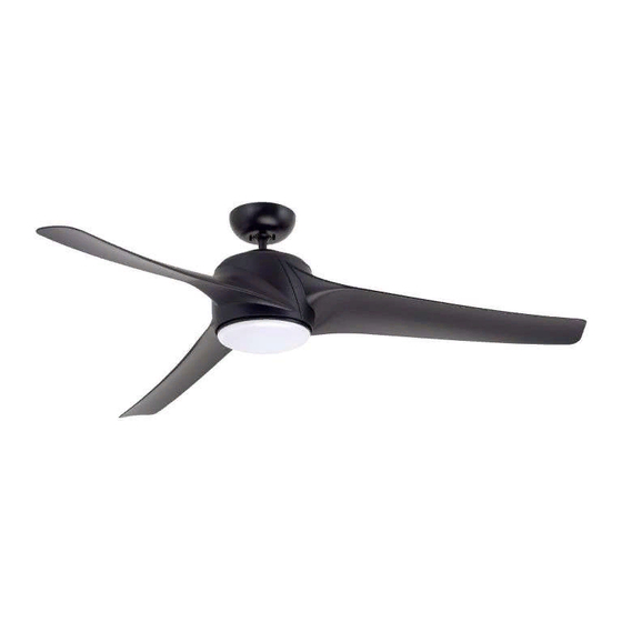
BP7515 CF860 Luray Eco
READ AND SAVE THESE INSTRUCTIONS
Ceiling Fan Owner's Manual
CF860BQ00 -
CF860PT00 -
CF860WW00 -
Emerson Electric Customer Service - 8 a.m. - 6 p.m., Eastern, Monday-Friday
Part No. F40BP75150000
Revision: 160104
1/4/16
2:35 PM
Page 1
LURAY ECO
60" Damp Location
Model Numbers
Net Weight:
Questions, problems, missing parts: Before returning to the store call
1-800-654-3545
www.emersonfans.com
™
Barbeque Black
Platinum
Appliance White
20.02
Lbs.
• Español - página 34
• Français - page 67
Form No. BP7515
ETL Model No.: CF860
Advertisement
Table of Contents

Related Manuals for Emerson LURAY ECO CF860BQ00


Summary of Contents for Emerson LURAY ECO CF860BQ00
- Page 1 20.02 Net Weight: Lbs. Questions, problems, missing parts: Before returning to the store call Emerson Electric Customer Service - 8 a.m. - 6 p.m., Eastern, Monday-Friday • Español - página 34 1-800-654-3545 • Français - page 67 Part No. F40BP75150000 Form No.
-
Page 2: Table Of Contents
2. All wiring must be in accordance with the National by Emerson could result in personal injury or property Electrical Code “ANSI/NFPA 70-2014” and Local damage. Electrical Codes. Use the National Electrical Code if Local Codes do not exist. -
Page 3: Unpacking Instructions
Emerson Electric Co. Substitution of parts or Shade accessories not designated for use with this product No-Light Plate by Emerson Electric Co. could result in personal injury or property damage. Wall Control Open carton containing fan. Remove top half of styrofoam unit. -
Page 4: Electrical Requirements
DC Receiver and Fan Wall Control. This system allows One Phillips head screwdriver One stepladder you to regulate your ceiling fan speed and light control. One 1/4” blade screwdriver One wire stripper This Emerson Ceiling Fan may be used with the Materials following accessory (purchased separately): SR600 Remote Control. -
Page 5: Ceiling Fan Assembly
BP7515 CF860 Luray Eco 1/4/16 2:35 PM Page 5 3. Ceiling Fan Assembly Flip the upper foam pad over and place on a stable FAN MOTOR working surface. ASSEMBLY Remove the fan motor assembly from the protective plastic bag. Place fan motor assembly on top of the foam pad with the upper motor cover supporting the weight of the motor (Figure 1). - Page 6 BP7515 CF860 Luray Eco 1/4/16 2:35 PM Page 6 3. Ceiling Fan Assembly (Continued) ROTATE CLOCKWISE LIGHT KIT ADAPTER Remove one of the three pan head screws from the motor assembly hub, retain the screw for future use. PAN HEAD SCREW Loosen the remaining two screws (Figure 3).
- Page 7 BP7515 CF860 Luray Eco 1/4/16 2:35 PM Page 7 3. Ceiling Fan Assembly (Continued) BLADE SCREWS NOTE: Installation of the blade will be complete (2 per blade after this step: assembly) Align the two blade tab holes of one blade with the BLADE threaded holes of the motor and install a washer head ASSEMBLY (3)
- Page 8 BP7515 CF860 Luray Eco 1/4/16 2:35 PM Page 8 3. Ceiling Fan Assembly (Continued) TWO 80" MOTOR LEADS (UNTWISTED) Separate, untwist and unkink the two 80” motor leads. Route the two motor leads through the 4.5” downrod (Figure 7). 4.5" DOWNROD Figure 7 Loosen the two Phillips head setscrews in the motor coupler for installation of the downrod (Figure 8).
- Page 9 BP7515 CF860 Luray Eco 1/4/16 2:35 PM Page 9 3. Ceiling Fan Assembly (Continued) 3.10 4.5" DOWNROD Make sure the grommet is properly installed in the motor coupler cover, then slide the motor coupler cover COUPLER on the downrod until it rests on the motor housing COUPLER COVER COVER GROMMET...
-
Page 10: How To Hang Your Ceiling Fan
BP7515 CF860 Luray Eco 1/4/16 2:35 PM Page 10 3. Ceiling Fan Assembly (Continued) 3.13 1/2-INCH The fan comes with black and white leads that are 80-inches long. BLACK WIRE Measure up approximately 6 to 9-inches above top of WHITE WIRE hanger ball/4.5”... - Page 11 BP7515 CF860 Luray Eco 1/4/16 2:35 PM Page 11 4. How to Hang Your Ceiling Fan (Continued) WARNING The outlet box and joist must be securely mounted and capable of supporting at least 50 lbs. Use only a U.L. outlet box listed as “Acceptable for Fan Support of OUTLET BOX 22.7 kg.
-
Page 12: Light Kit Assembly
BP7515 CF860 Luray Eco 1/4/16 2:35 PM Page 12 5. Light Kit Assembly REMOVE LIGHT Remove one of the three screws in the Light Kit Adapter KIT ADAPTER PAN and loosen the remaining two screws (Figure 17). HEAD SCREW Retain the screw for future use. Engage the fan motor assembly black wire connector FAN MOTOR ASSEMBLY WHITE WIRE CONNECTOR... -
Page 13: Optional Installation Of No-Light Plate Assembly
BP7515 CF860 Luray Eco 1/4/16 2:35 PM Page 13 6. Optional Installation of No-Light Plate Assembly Removal of the Shade from the Light Kit Adapter: Rotate the Shade counter-clockwise to loosen from the Light Kit Adapter (Figure 20). Remove the Shade from the Light Kit Adapter (Figure 20). -
Page 14: How To Wire Your Ceiling Fan
(this may be a accessories not designated for use with this product bare wire or wire with green colored insulation). by Emerson Electric Co. could result in personal injury Securely connect wires with wire connectors (supplied) or property damage. - Page 15 BP7515 CF860 Luray Eco 1/4/16 2:35 PM Page 15 7. How to Wire Your Ceiling Fan (Continued) Securely connect the fan motor white wire to the supply white (neutral) wire using wire connector (supplied) SUPPLY WHITE (Figure 25). (NEUTRAL) LISTED WIRE CONNECTOR FAN MOTOR WHITE WIRE...
-
Page 16: How To Wire Your Ceiling Fan
BP7515 CF860 Luray Eco 1/4/16 2:35 PM Page 16 7. How to Wire Your Ceiling Fan (Continued) Screw the two threaded studs (supplied) into the tapped holes in the hanger bracket (Figure 28). THREADED STUDS (2) Figure 28 Lift the ceiling cover up to the threaded studs and turn until studs protrude through the holes in the ceiling cover (Figure 29). -
Page 17: Light Kit Assembly Replacement
BP7515 CF860 Luray Eco 1/4/16 2:35 PM Page 17 8. Light Kit Assembly Replacement Repair of the Light Kit can be Accomplished By; 1) Replacing the Entire Light Kit Assembly or; 2) Replacing the Driver or Array Components Individually. WARNING METHOD 1- REPLACING THE ENTIRE LIGHT Turning off wall switch is not sufficient. - Page 18 BP7515 CF860 Luray Eco 1/4/16 2:35 PM Page 18 8. Light Kit Assembly Replacement (Continued) Disengage the fan motor assembly black wire connector from the black wire connector of the new Light Kit FAN MOTOR Assembly (Figure 32). ASSEMBLY BLACK WIRE Disengage the fan motor assembly white wire connector CONNECTOR from the white wire connector of the new Light Kit...
- Page 19 BP7515 CF860 Luray Eco 1/4/16 2:35 PM Page 19 8. Light Kit Assembly Replacement (Continued) 8.10 LIGHT KIT ASSEMBLY LIGHT KIT ASSEMBLY Remove the paper backing from the adhesive foam tape DRIVER TWO PIN ARRAY CONNECTOR on the bottom of the new Light Kit Assembly Driver. CONNECTOR Place the new Light Kit Assembly Driver into the assembly, aligning it directly where the old Driver had...
-
Page 20: Light Kit Assembly Replacement
BP7515 CF860 Luray Eco 1/4/16 2:35 PM Page 20 8. Light Kit Assembly Replacement (Continued) 8.14 PLASTIC PHILLIPS HEAD SCREWS (3) Unscrew the three plastic Phillips head screws securing the Light Kit Assembly Array to the Light Kit Assembly LIGHT KIT (Figure 37). -
Page 21: Wall Control Installation
Restore electricity and verify function of the light kit. 9. Wall Control Installation Preset Memory Feature: Your Emerson receiver is Your Emerson Ceiling Fan/Light Control consists of wall equipped with a preset memory feature. If the AC mounted transmitter and a receiver located inside the supply to the receiver is powered OFF through a wall motor assembly. -
Page 22: Warning
BP7515 CF860 Luray Eco 1/4/16 2:35 PM Page 22 9. Wall Control Installation (Continued) WALL CONTROL Your wall control has code switches which must be set CODE SWITCHES 1 - 5 in one of 32 possible code combinations (Figure 41). The five levers (numbered 1, 2, 3, 4, and 5) on the switches are factory-set in the ON (up) position. -
Page 23: Warning
BP7515 CF860 Luray Eco 1/4/16 2:35 PM Page 23 9. Wall Control Installation (Continued) Screw wall control into wall box using the supplied screws. Leave wall control in “OFF” mode until fan Disconnect electrical power to the branch circuit at the installation is completed. -
Page 24: Warning
BP7515 CF860 Luray Eco 1/4/16 2:35 PM Page 24 9. Wall Control Installation (Continued) 3-WAY INSTALLATION FAN/LIGHT (One fan controlled by two different wall controls) WALL (See Figures 45 and 46). CONTROL WARNING BLACK Turning off wall switch is not sufficient. To avoid LOAD TRAVELER possible electrical shock, be sure electricity is turned... - Page 25 BP7515 CF860 Luray Eco 1/4/16 2:35 PM Page 25 9. Wall Control Installation (Continued) 3-WAY WIRING DIAGRAM: STANDARD WIRING FOR EXISTING NEW CONSTRUCTION 3-WAY CONTROLS NOTE: Retrofit 3-way installations are likely to EXISTING include two traveler wires between the two wall WALL CONTROL boxes.
-
Page 26: Programming The Receiver Operating Frequency & High Speed Conditioning Of Fan Control
BP7515 CF860 Luray Eco 1/4/16 2:35 PM Page 26 10. Programming the Receiver Operating Frequency & High Speed Conditioning of Fan Control -- Important - Read This Section Carefully and Follow the High Speed Conditioning Instructions Closely -- PROGRAMMING THE RECEIVER 10.2 OPERATING FREQUENCY &... -
Page 27: Using Your Ceiling Fan
BP7515 CF860 Luray Eco 1/4/16 2:35 PM Page 27 11. Using Your Ceiling Fan WARNING Fan installation must be completed, including the POWER installation of the fan blades, before testing the wall INDICATOR control. LIGHT LIGHT AIRFLOW INTENSITY Your wall control has full control of your fan and light DIRECTION BUTTON (Figure 47). -
Page 28: Maintenance
Emerson Electric Co. Substitution of parts or accessories not designated for use with this product WARNING by Emerson Electric Co. could result in personal injury or property damage. The use of any other control not specifically approved for this fan could result in fire, shock and personal injury. -
Page 29: Troubleshooting
BP7515 CF860 Luray Eco 1/4/16 2:35 PM Page 29 15. Troubleshooting WARNING FOR YOUR OWN SAFETY TURN OFF POWER AT FUSE BOX OR CIRCUIT BREAKER BEFORE TROUBLESHOOTING YOUR FAN. TROUBLE PROBABLE CAUSE SUGGESTED REMEDY 1. Fan will not start. 1. Loose electrical connections in the 1. -
Page 30: Repair Parts
BP7515 CF860 Luray Eco 1/4/16 2:35 PM Page 30 16. Repair Parts PARTS BAG ETL Model No.: CF860... - Page 31 BP7515 CF860 Luray Eco 1/4/16 2:35 PM Page 31 16. Repair Parts Listing Model Numbers Description CF860BQ00 CF860PT00 CF860WW00 Hanger Ball Assembly, 761655- 19 761655-101 761655-0 Consisting of: Hanger Bracket (1) — — — Hanger Ball (1) — — — 4.5”...
-
Page 32: Bp7515 Cf860 Luray Eco 1/4/16 2:35 Pm
BP7515 CF860 Luray Eco 1/4/16 2:35 PM Page 32 INSTRUCTION TO THE USER (if device contains a digital device) This equipment has been tested and found to comply with the limits for a class B digital device, pursuant to part 15 of the FCC Rules. -
Page 33: Ceiling Fan Limited Warranty
Manual or other instructions provided by Emerson to you with the Emerson Ceiling Fan). LED drivers are covered for a period of three (3) years, and any LED array is covered for a period of five (5) years. All other components and accessories of the Emerson Ceiling Fan are covered by this limited warranty for a period of one (1) year. All warranty periods begin on the date of original retail purchase. -
Page 34: Spanish
You should record this data above and keep it in a safe place for future use. Air Comfort Products DIVISION OF EMERSON ELECTRIC CO. 8100 W. Florissant • St. Louis, MO 63136 Questions, problems, missing parts: Before returning to the store call Emerson Electric Customer Service 8 a.m.
Need help?
Do you have a question about the LURAY ECO CF860BQ00 and is the answer not in the manual?
Questions and answers