Table of Contents
Advertisement
Quick Links
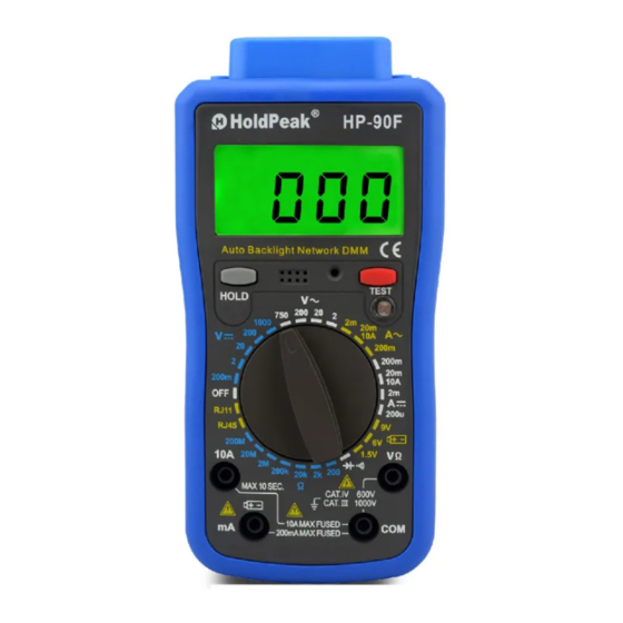
NETWORK DIGITAL MULTIMETER
OPERATOR'S MANUAL
1. Overview
The network multimeter is characterized at slim size, portable, stable performance and anti-dropping
capacity. Using 3 1/2 digits LCD monitor with character 16mm high, they offer clear readings. With
overall circuitry design centering on large-scale IC A/D converters in conjunction and over-load
protection circuit, the meters give excellent performance and exquisite making as a handy utility
instrument.
The meter can be used to measure DC & AC voltage, DC & AC current, resistance, battery, positive
diode voltage fall and audible continuity. It can be used to test network cable (RJ45) and telephone
line (RJ11) too.
2. Panel Layout
LCD display: 3 1/2 digits LCD display.
①
HOLD key: Press the "HOLD" key to lock display value, and the "
②
display, press it again to exit.
TEST key: Switch to RJ11 or RJ45 range and connect the telephone line or network cable with
③
the instrument, Press "TEST", the result will show on the LCD screen.
CDS sensor: The CDS sensor can reaction to the ambient brightness range, then automatically
④
control the LCD backlight to lighten or go out.
Rotary Switch: Use this switch to select functions and ranges.
⑤
10A: 10A Input Jack
⑥
VΩ: V
Input Jack
⑦
mA: mA and battery test Input Jack
⑧
COM: COM Input Jack
⑨
Network cable (RJ45) test Jack
⑩
⑪
Telephone line (RJ11) test Jack
⑫
Cover of the network test Jack
⑬
Crust of meter
⑭
Protective casing
3. Safety Information
3-1 The meters are designed according to IEC-1010 concerning electronic measuring instruments with
an over-voltage category CAT Ⅲ 1000V & CAT Ⅳ 600V and pollution 2.
3-2 Follow all safety and operating instructions to ensure that the meter is used safely and is kept in
good operating condition.
3-3 safety symbols:
Important safety information, refer to the operating manual.
Dangerous voltage may be presence.
Double insulation (protection Class II)
4. Special Cautions for Operation
4-1 The meters can be safe only according to standard procedures when used in conjunctions with the
supplied test leads. To replace damaged test leads with only the same model or same electric
specifications.
4-2 To avid risk of electric shock, do not use the meters before the cover is in place.
4-3 The range switch should be right position for the testing.
4-4 To avoid electric shock and damaging the instruments, the input signals are forbidden to exceed
the specified limits.
4-5 When measuring TV set or switched power, attention should be paid to the possible pulses that
may bring destruction to the circuit.
4-6 Range switch position is forbidden to be changed at random during measurement.
4-7 Take caution against shock in the course of measuring voltage higher than DC 60V & AC 30V.
4-8 Please do not remove the network test cover while not test the network, avoiding a risk of electric
shock.
4-9 Protection fuse should be replaced only with same type and same specification.
4-10 After operation is finished, set function switch at OFF range to save battery power.
4-11 If the meter is without usage for long time, take out battery to avoid damage by battery leakage.
5. GENERAL SPECIFICATIONS
5-1 Max Voltage between input terminal and Earth Ground: CAT Ⅲ 1000V & CAT Ⅳ 600V.
5-2 Over-range Indication: display "1" or "-1" for the significant digit.
5-3 Automatic display of negative polarity "-" .
5-4 Low Battery Indication: "
" displayed.
5-5 Data hold Indication: "
" displayed.
5-6 Network cable (RJ45) test Indication: "
5-7 Telephone line (RJ11) test Indication: "
5-8 Display: 3 1/2 digit LCD with a max. reading of 1999.
5-9 Manual range control
5-10 Auto LCD backlight
5-11 Fuse protection: 200mA/500V & 10A/500V Fast Fuse
5-12 Power supply: 9V battery (6F22 or NEDA 1604)
5-13 Operating Temp. : 0℃ to 40℃ (relative humidity <85%)
5-14 Storage Temp. : -10℃ to 50℃ (relative humidity <85%)
5-15 Guaranteed precision Temp. : 23± 5℃ (relative humidity <70%)
5-16 Dimension: 180x88x51mm
5-17 Weight: approx. 320g (including battery)
HP-90F
" sign will appear on the
" displayed.
" displayed.
6. Testing Specifications
Accuracy is specified for a period of year after calibration and at 18℃ to 28℃ (64℉ to 82℉)
with relative humidity to 70%.
6-1 DC Voltage
Range
Resolution
200mV
0.1mV
2V
1mV
20V
10mV
200V
100mV
1000V
1V
-- Impedance: 10MΩ
-- Overload protection: 1000V DC or 750V AC rms
6-2 AC Voltage
Range
Resolution
2V
1mV
20V
10mV
200V
100mV
750V
1V
-- Impedance: 10MΩ (2V range is 1MΩ)
-- Overload protection: 1000V DC or 750 AC rms
-- Frequency Range: 40 to 400Hz
-- Response: average, calibrated in rms of sine wave
6-3 DC Current
Range
Resolution
200μA
0.1μA
2mA
1μA
20mA
10μA
200mA
100μA
10A
10mA
-- Overload protection: 200mA/500V & 10A/500V Fast Fuse
Note: 10A up to 10 seconds
6-4 AC Current
Range
Resolution
2mA
1μA
20mA
10μA
200mA
100μA
10A
10mA
-- Overload protection: 200mA/500V & 10A/500V Fast Fuse
Note: 10A up to 10 seconds
-- Frequency Range: 40 to 400Hz
-- Response: average, calibrated in rms of sine wave
6-5 Resistance
Range
Resolution
200Ω
0.1Ω
2kΩ
1Ω
20kΩ
10Ω
200kΩ
100Ω
2MΩ
1kΩ
20MΩ
10kΩ
200MΩ
100kΩ
-- Overload protection: 500V DC or AC rms
6-6 Diode and Audible continuity test
Range
Description
Display read approximately
forward voltage of diode
Built-in buzzer sounds if
resistance is less than 50Ω
Overload protection: 500V DC or AC rms
6-7 Battery test
Range
Accuracy
1.5V
± (5.0% of rdg + 5 digits)
6V
9V
Overload protection: 200mA/500V Fast Fuse
6-8 Telephone line (RJ11) test
◆ Normal operation of telephone line: "PASS" symbol will appear on the LCD display,
◆ Abnormal operation of telephone line: "FAULT" symbol will appear on the LCD display.
6-9 Network cable (RJ45) test
◆ Normal network cables connecting: Correct connecting symbol, such as "1-2" or "3-6" will appear
on the LCD screen.
◆ Open circuit of network cables connecting: Open Circuit of network cables connecting will not
display on the LCD screen. For example, if 1-2 network cable is open circuit, "1-2" will not display
on the LCD screen.
◆ Short circuit of network cables: The symbol of short circuit of network cables will display on the
LCD screen. For example, if cable 1-2 is short circuit, "1-2", "SHO." will display on the LCD screen.
◆ Misconnection of network cables: The symbol of misconnection of network cables will display on
the LCD screen. For example, if cable 1-2 is misconnecting, "1-2", "MIS." will display on the LCD
screen.
◆ Reverse connection of network cables: The symbol of reverse connection of network cables will
display on the LCD screen. For example, if cable 1-2 is reverse connecting, "1-2", "REV." will
display on the LCD screen.
◆ Split pairs of network cables: The Split pairs network cables will display on the LCD screen. For
example, if cable 1-2 and 3-6 are split pairs, "1-2","3-6", "SPL." will display on the LCD screen.
◆ Shield of network cable: If shield of network cable is normal, "SHIELD" will display on the LCD
screen, if shield of network cable is open circuit or not excite, "SHIELD" will not display on the LCD
Screen.
Accuracy
± (0.5% of rdg + 2 digits)
± (0.8% of rdg + 2 digits)
Accuracy
± (1.0% of rdg + 2 digits)
± (1.2% of rdg + 3 digits)
Accuracy
± (1.2% of rdg + 2 digits)
± (2.0% of rdg + 3 digits)
Accuracy
± (1.5% of rdg + 3 digits)
± (2.5% of rdg + 5 digits)
Accuracy
± (1.0% of rdg + 3 digits)
± (1.0% of rdg + 2 digits)
± (1.5% of rdg + 3 digits)
± (5.0% of rdg + 10 digits)
Test Condition
Forward DC current
approx. 1mA
Reversed DC voltage
approx. 3V
Open circuit voltage
approx. 3V
Load Resistance
Resolution
Approx. 30Ω
10mV
Approx. 68Ω
Approx. 909Ω
Advertisement
Table of Contents

Subscribe to Our Youtube Channel
Related Manuals for HoldPeak HP-90F


Summary of Contents for HoldPeak HP-90F
- Page 1 6. Testing Specifications Accuracy is specified for a period of year after calibration and at 18℃ to 28℃ (64℉ to 82℉) HP-90F with relative humidity to 70%. NETWORK DIGITAL MULTIMETER 6-1 DC Voltage Range Resolution Accuracy OPERATOR’S MANUAL 200mV 0.1mV 1.
- Page 2 7. OPERATING INSTRUCTIONS 7-9 Telephone Line (RJ11) Testing 7-9-1 Open the cover of the network test on the top of the instrument by a screwdriver, take out the 7-1 Attention before operation 7-1-1 Check battery. When the battery voltage drop below proper operation range, the “ ”...
Need help?
Do you have a question about the HP-90F and is the answer not in the manual?
Questions and answers