
Related Manuals for Fervi 0050

Summary of Contents for Fervi 0050
- Page 1 OPERATION AND MAINTENANCE MANUAL Air die grinder set with sanding attachments Art. 0050 ORIGINAL INSTRUCTIONS...
- Page 2 Manual on the date of issue, listed on this page; however, the machine may be subject to potentially major technical changes in the future, without the Manual being updated. Therefore, see FERVI for information about modifications that could be implemented. REV. 2 October 2013...
-
Page 3: Table Of Contents
HARDWARE CONTENTS GENERAL SAFETY INSTRUCTIONS............. 4 Risks Associated with the Work Area ................4 Risks Associated with the Presence of Rotating and/or Moving Parts......4 Personal protective equipment ..................5 Technical support......................5 DESCRIPTION OF THE GRINDER AND INTENDED USE ....... 6 Technical specifications ....................7 Pictograms ........................7 Identification plates......................7 IMPROPER USE AND CONTRAINDICATIONS.......... -
Page 4: General Safety Instructions
HARDWARE 1 GENERAL SAFETY INSTRUCTIONS 1. During use, maintain control of the tool. The operators represent the most important aspect of safety. To best protect against the risk of injury, work cautiously and carefully. 2. The pneumatic tool should not be used and repaired by someone under the influence of drugs or alcohol. -
Page 5: Personal Protective Equipment
HARDWARE 1.3 Personal protective equipment When using the pneumatic tool, always wear the following: Hearing protection Safety shoes Work gloves Protective goggles (cap, earplugs, etc.) 1.4 Technical support For any problems and/or concerns, please contact, without hesitation, the Customer Service Department of the dealer, who has specialised staff, specific equipment and spare parts. -
Page 6: Description Of The Grinder And Intended Use
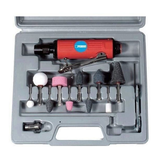
By changing the abrasive tools (grinding wheels), it is possible to grind or polish different materials, such as metals, wood and plastic. The grinder Art. 0050 is made up of the following parts (see Figure 1): Figure 1 – Grinder blow mould case Art. 0050. -
Page 7: Technical Specifications
HARDWARE 2.1 Technical specifications Operating pressure Air intake 600 / 6 (kPa/bar) (l/min) Rotation speed Empty weight 22,000 (rev/min) (kg) Sound pressure level emitted into the environment (dB (A)) 82.5 Vibration transmitted to the hand-arm system (m/s <2.5 2.2 Pictograms An obligation pictogram is affixed to each machine: CAREFULLY READ THE OPERATION AND MAINTENANCE MANUAL BEFORE USING THE TOOL! -
Page 8: Improper Use And Contraindications
HARDWARE 3 IMPROPER USE AND CONTRAINDICATIONS IT IS STRICTLY FORBIDDEN !! Allow the tool to be used by untrained personnel and those who have not read the instruction manual; Use the tool for different purposes and uses other than those for which it was designed, i.e. -
Page 9: Commissioning
HARDWARE 4 COMMISSIONING 1. Remove the air inlet cap, then screw the nozzle into hole: 1/4" NPT Male Quick-Release Coupling 2. Put a few drops of lubricating oil (without resin acid) in the air inlet nozzle. 3. Check the flexible air supply hose. If it is damaged, broken, torn or deformed it must not be connected to the tool. -
Page 10: How To Use
HARDWARE 5 HOW TO USE 5.1 Attaching the abrasive tools (grinding wheels) Crushing and Cutting Before attaching and/or removing the grinding wheels, always remove the air supply hose. Protective gloves Before attaching and/or removing the grinding wheels, wear suitable protective gloves. 1. - Page 11 HARDWARE Crushing and Cutting Always be sure to insert the shaft of the grinding wheel into the hole of the tool chuck by at least 10mm. Always make sure that the tool is assembled correctly while trying to manually remove it from the grinder.
-
Page 12: Power On / Off
HARDWARE 5.2 Power On / Off (Personal Protective Equipment) PPE Before using the grinder, wear suitable work clothing, gloves, shoes and protective goggles. Also wear a mask if you work with materials that produce dust or fumes. Also wear protective devices for the ears (hearing protectors), such as earmuffs, earplugs, etc. - Page 13 HARDWARE To start the grinder (to rotate the tool), press the safety lever forward with your thumb (Figure 8/A), then press the lever against the housing of the grinder (Figure 8/B). Figure 8 - Starting the grinder. The grinder's start lever is a continuous hold lever, in the sense that the function controlled (i.e., the rotation of the grinding wheel) is active as long as the lever itself is kept pressed.
-
Page 14: Maintenance And Cleaning
HARDWARE 6 MAINTENANCE AND CLEANING The purpose of this chapter is to provide all the information on maintenance procedures and their frequency as required by the Grinder. Frequency INTERVENTION Daily Weekly 1. General visual inspection 2. General cleaning 3. Clean the air outlet nozzle 4. -
Page 15: Bill Of Materials And Spare Parts
HARDWARE 7 BILL OF MATERIALS AND SPARE PARTS Page 15 of 16... - Page 16 0050/27 Bearing 0050/11 O-ring 0050/28 Intake 0050/12 Nut 0050/29 Lock ring nut 0050/13 O-ring 0050/30 Washer 0050/14 Release ring nut 0050/31 Coupling 1/4” 0050/15 O-ring 0050/32 Connection nut 0050/16 Inlet coupling 0050/33 Hex wrench 0050/17 Rubber coating 0050/34 Coupling 1/8”...
Need help?
Do you have a question about the 0050 and is the answer not in the manual?
Questions and answers