Table of Contents
Advertisement
Advertisement
Table of Contents

Subscribe to Our Youtube Channel
Related Manuals for MINN KOTA EDGE


Summary of Contents for MINN KOTA EDGE
- Page 1 EDGE BOW-MOUNT TROLLING MOTOR USER MANUAL...
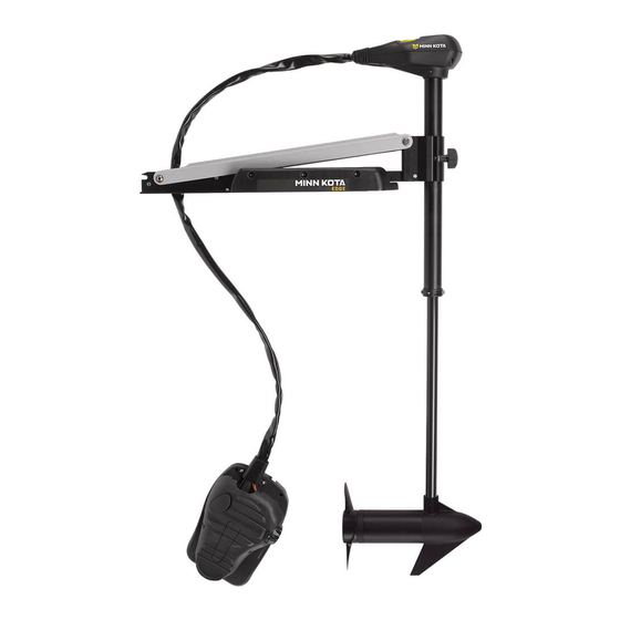
- Page 2 FEATURES Directional Indicator Mounting Bracket Latch & Door Depth Adjustment Knob Lifetime Warranty Flexible Composite Shaft Momentary Switch Rotary Speed Control Mom/Off/Con Switch Cool Quiet Power Motor Heel Block Propeller Specifications subject to change without notice. *This diagram is for reference only and may differ from your actual motor.
-
Page 3: Mount Installation
3. Place the motor on top of the desired mounting location while it is in the stowed position (for stow and deploy instructions, see "Stowing and Deploying the Motor" on p. 11). 4. Verify the motor rest is positioned far enough beyond the edge of the boat so that the motor clears all obstructions while deploying and stowing the motor. - Page 4 MOUNT INSTALLATION 5. Deploy the motor and remove the motor assembly from the mount by loosening the Steering Tension Knob and opening the door. WARNING: When raising or lowering motor, keep fi ngers clear of all hinge and pivot points and all moving parts. Depth Adjustment Knob Motor Assembly 6.
-
Page 5: Battery Wiring & Installation
CAUTION: These guidelines apply to general rigging to support your Minn Kota motor. Powering multiple motors or additional electrical devices from the same power circuit may impact the recommended conductor gauge and circuit breaker size. If you are using wire longer than that provided with your unit, follow the conductor gauge and circuit breaker sizing table below. -
Page 6: Selecting The Correct Batteries
• It is highly recommended that a circuit breaker or fuse be used with this trolling motor. Refer to “Conductor Gauge and Circuit Breaker Sizing Table” in the previous section to fi nd the appropriate circuit breaker or fuse for your motor. For motors requiring a 60-amp breaker, the Minn Kota MKR-19 60-amp circuit breaker is recommended. CONNECTING THE BATTERIES 12 VOLT SYSTEMS: 1. -
Page 7: Motor Wiring Diagram
MOTOR WIRING DIAGRAM NOTE: This is a universal, multi-voltage diagram. Double-check your motor's voltage for proper connections. Over-Current Protection Devices not shown in this illustration. RED+ FIVE SPEED SWITCH TERMINAL BLOCK MOM/OFF/CON SWITCH MOMENTARY SWITCH BLACK/WHITE BLACK- RED+ BATTERY 1 MOT0R BATTERY 1 BATTERY 2... -
Page 8: Using And Adjusting The Motor
USING AND ADJUSTING THE MOTOR STOWING AND DEPLOYING THE MOTOR WARNING: When raising or lowering the motor, keep fi ngers clear of all hinge and pivot points and all moving parts. MOUNT FEATURES • The motor mount is designed to fold back and lock the motor fl at on the deck when not in use and to provide secure stowage for transport. -
Page 9: Adjusting The Depth Of The Motor
USING & ADJUSTING THE MOTOR ADJUSTING THE DEPTH OF THE MOTOR Depth Adjustment Knob The propeller tip must be submerged at least 12” to avoid churning or agitation of surface water. Outer Shaft 1. With the motor deployed, fi rmly grasp the outer shaft or control head and hold it steady. -
Page 10: Controlling Speed & Steering With The Foot Pedal
USING & ADJUSTING THE MOTOR CONTROLLING SPEED & STEERING WITH THE FOOT PEDAL Most controls on the foot pedal are easy to operate by either foot or hand: Toe End Speed Knob Momentary Button Directional Indicator Heel End Mom/Off /Con Switch TO ADJUST MOTOR SPEED Turn the speed knob clockwise to increase speed and counter-clockwise to decrease speed. -
Page 11: Service And Maintenance
7. The propeller is designed to provide weed free operation with very high effi ciency. To maintain this top performance, the leading edge of the blades must be kept smooth. If they are rough or nicked from use, restore to smooth by sanding with fi ne... -
Page 12: Troubleshooting And Repair
TROUBLESHOOTING & REPAIR 1. Motor fails to run or lacks power: • Check battery connections for proper polarity. • Make sure terminals are clean and corrosion free. Use fi ne sandpaper or emery cloth to clean terminals. • Check battery water level. Add water if needed. 2. -
Page 13: Parts Diagram
55 LBS THRU - 12 VOLT - 45”/52” SHA This page provides Minn Kota® WEEE compliance disassembly instructions. For more information about where you should dispose of your waste equipment for recycling and recovery and/or your European Union member state requirements, please contact your dealer or distributor from which your product was purchased. -
Page 14: Parts List
PARTS LIST EDGE 55 55 LBS THRU - 12 VOLT - 45”/52” SHA PART PART PART ITEM QTY DESCRIPTION ITEM QTY DESCRIPTION ITEM QTY DESCRIPTION NUMBER NUMBER NUMBER 2-100-117 SEMBLY 12 V 3.625 2251603 ROPE- 48” CONNE OR 1/4 MALE... -
Page 15: Environmental Compliance Statement
Minn Kota motors are not subject to the disposal regulations EAG-VO (electric devices directive) that implements the WEEE directive. Nevertheless never dispose of your Minn Kota motor in a garbage bin but at the proper place of collection of your local town council. -
Page 16: Recommended Accessories
Stop buying new batteries and start taking care of the ones you’ve got. Many chargers can actually damage your battery over time – creating shorter run times and shorter overall life. Digitally controlled Minn Kota chargers are designed to provide the fastest charge that protect and extend battery life.
Need help?
Do you have a question about the EDGE and is the answer not in the manual?
Questions and answers