Table of Contents
Advertisement
Quick Links
1
SERVICE MANUAL
Level 1&2
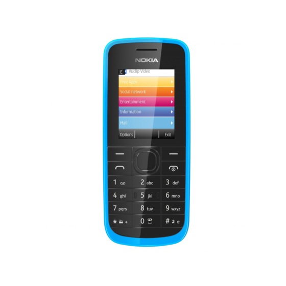
Nokia 109, C1-02i
RM-907
Nokia I nternal Use Only | Copyright © 2012 Nokia | A ll rights reserved
L1L2 Service Manual
Transceiver characteristics
Band
GSM 900/1800 MHz
GSM: 850/1900 MHz
Display
1.8" TFT display, 128x160 pixels
Operating System
S40
Connections
3.5mm AV Jack
2.0mm DC Jack
Micro SD card slot
FM Radio
GPRS/EGPRS
WAP 2.0
Transceiver with BL-5CB battery pack
Talk time
Standby
EGSM: Up to
EGSM: Up to
7h 50 min
790 hours
Note:
Talk times are dependent on network
parameters
and phone settings
Nokia 109, C1-02i
(RM-907)
V ersion 1.0
Advertisement
Table of Contents

Subscribe to Our Youtube Channel
Related Manuals for Nokia 109


Summary of Contents for Nokia 109
- Page 1 EGSM: Up to EGSM: Up to 7h 50 min 790 hours Note: Talk times are dependent on network parameters and phone settings Nokia I nternal Use Only | Copyright © 2012 Nokia | A ll rights reserved V ersion 1.0...
-
Page 2: Table Of Contents
SERVICE DEVICES ................................10 SOFTWARE UPDATE ..............................11 DISASSEMBLY INSTRUCTIONS ..........................12 10. ASSEMBLY HINTS ................................17 11. SOLDER COMPONENTS ............................... 18 Nokia I nternal Use Only | Copyright © 2012 Nokia | A ll rights reserved V ersion 1.0... - Page 3 The purpose of this document is to help NOKIA service levels 1 and 2 workshop technicians to carry out service to NOKIA products. This Service Manual is to be used only by authorized NOKIA service suppliers, and the content of it is confidential. Please note that NOKIA provides also other guidance documents (e.g.
-
Page 4: Copyright
Under no circumstances shall Nokia be responsible for any loss of data or income or any special, incidental, consequential or indirect damages howsoever caused. The contents of this document are provided “as is”. Except as required by applicable law,... -
Page 5: Warnings And Cautions
4. Ensure all components, modules screws and insulators are correctly re –fitted after servicing and alignment. 5. Ensure all cables and wires are repositioned correctly Nokia I nternal Use Only | Copyright © 2012 Nokia | A ll rights reserved V ersion 1.0... -
Page 6: Esd Protection
ESD Protected Area. For more information and local requirements about ESD protection and ESD Protected Area, contact your local Nokia After Market Services representative. Nokia I nternal Use Only | Copyright © 2012 Nokia | A ll rights reserved V ersion 1.0... -
Page 7: Care And Maintenance
All of the above suggestions apply equally to the product, battery, charger or any accessory. Nokia I nternal Use Only | Copyright © 2012 Nokia | A ll rights reserved V ersion 1.0... -
Page 8: Battery Information
Do not dispose batteries in a fire! Dispose of batteries according to local regulations (e.g. recycling). Do not dispose as household waste. Nokia I nternal Use Only | Copyright © 2012 Nokia | A ll rights reserved V ersion 1.0... -
Page 9: Exploded View
SIZE 4 RF1.4 x 5.0 B-COVER I0019 I0020 Only available Not reuseable Repair/swap v1.0 as assembly after removal only in level 3 Nokia I nternal Use Only | Copyright © 2012 Nokia | A ll rights reserved V ersion 1.0... -
Page 10: Service Devices
Nokia Online. Supplier or SF-278 Flash adapter manufacturer contacts for tool re-order can be found in “Recommended service equipment” document on Nokia Online. Nokia I nternal Use Only | Copyright © 2012 Nokia | A ll rights reserved V ersion 1.0... -
Page 11: Software Update
To use the FLS-5 Flash Dongle, follow the user guide inside the sales package. Please check always for the latest version of flash software, which is available on Nokia Online. Nokia I nternal Use Only | Copyright © 2012 Nokia | A ll rights reserved V ersion 1.0... -
Page 12: Disassembly Instructions
SRT-6 towards the bottom end to release the side of the A- COVER. Nokia I nternal Use Only | Copyright © 2012 Nokia | A ll rights reserved V ersion 1.0... - Page 13 11) Push out the KEYMAT as shown and remove it. 12) Unscrew the four TORX+ size 4 screws in the order shown. Nokia I nternal Use Only | Copyright © 2012 Nokia | A ll rights reserved V ersion 1.0...
- Page 14 17) Lift up the DC JACK with a DC plug. Remove it 18) Release the MFD BARD with the dental tool with tweezers. and remove it with tweezers. Nokia I nternal Use Only | Copyright © 2012 Nokia | A ll rights reserved V ersion 1.0...
- Page 15 DISPLAY FLEX. 23) Remove also the EARPIECE adhesive remains 24) Remove the KEYMAT LIGHT GUIDE. from the UI SHIELDING. Nokia I nternal Use Only | Copyright © 2012 Nokia | A ll rights reserved V ersion 1.0...
- Page 16 27) Now the Nokia 109/C1-02i disassembly procedure is complete. -END OF DISSASEMBLY - Nokia I nternal Use Only | Copyright © 2012 Nokia | A ll rights reserved V ersion 1.0...
-
Page 17: Assembly Hints
2) Tighten the two TORX+ size 4 screws to the torque of 14 Ncm in the order shown. torque of 14 Ncm in the order shown. Nokia I nternal Use Only | Copyright © 2012 Nokia | A ll rights reserved V ersion 1.0... -
Page 18: Solder Components
Nokia 109, C1-02i (RM-907) L1L2 Service Manual 11.SOLDER COMPONENTS BOTTOM Charger Fuse F2051 V2406 v1.0 Nokia I nternal Use Only | Copyright © 2012 Nokia | A ll rights reserved V ersion 1.0... - Page 19 www.s-manuals.com...
Need help?
Do you have a question about the 109 and is the answer not in the manual?
Questions and answers