Table of Contents
Advertisement
Copyright
This publication, including all photographs, illustrations and software, is protected
under international copyright laws, with all rights reserved. Neither this manual, nor
any of the material contained herein, may be reproduced without written consent of
the author.
Version 3.0
Disclaimer
The information in this document is subject to change without notice. The manufac-
turer makes no representations or warranties with respect to the contents hereof and
specifically disclaims any implied warranties of merchantability or fitness for any
particular purpose. The manufacturer reserves the right to revise this publication and
to make changes from time to time in the content hereof without obligation of the
manufacturer to notify any person of such revision or changes.
Trademark Recognition
Microsoft, MS-DOS and Windows are registered trademarks of Microsoft Corp.
AMD, Phenom, Athlon, Sempron and Duron are registered trademarks of AMD
Corporation.
Other product names used in this manual are the properties of their respective
owners and are acknowledged.
Federal Communications Commission (FCC)
This equipment has been tested and found to comply with the limits for a Class B
digital device, pursuant to Part 15 of the FCC Rules. These limits are designed to
provide reasonable protection against harmful interference in a residential installa-
tion. This equipment generates, uses, and can radiate radio frequency energy and, if
not installed and used in accordance with the instructions, may cause harmful inter-
ference to radio communications. However, there is no guarantee that interference
will not occur in a particular installation. If this equipment does cause harmful
interference to radio or television reception, which can be determined by turning the
equipment off and on, the user is encouraged to try to correct the interference by one
or more of the following measures:
•
Reorient or relocate the receiving antenna.
•
Increase the separation between the equipment and the receiver.
•
Connect the equipment onto an outlet on a circuit different from that to
which the receiver is connected.
•
Consult the dealer or an experienced radio/TV technician for help.
Shielded interconnect cables and a shielded AC power cable must be employed with
this equipment to ensure compliance with the pertinent RF emission limits govern-
ing this device. Changes or modifications not expressly approved by the system's
manufacturer could void the user's authority to operate the equipment.
Preface
Preface
Advertisement
Table of Contents

Related Manuals for ECS A75F-M2


Summary of Contents for ECS A75F-M2
- Page 1 Preface Copyright This publication, including all photographs, illustrations and software, is protected under international copyright laws, with all rights reserved. Neither this manual, nor any of the material contained herein, may be reproduced without written consent of the author. Version 3.0 Disclaimer The information in this document is subject to change without notice.
-
Page 2: Declaration Of Conformity
Declaration of Conformity This device complies with part 15 of the FCC rules. Operation is subject to the following conditions: • This device may not cause harmful interference. • This device must accept any interference received, including interfer- ence that may cause undesired operation. Canadian Department of Communications This class B digital apparatus meets all requirements of the Canadian Interference- causing Equipment Regulations. -
Page 3: Table Of Contents
T T T T T ABLE OF CONTENTS ABLE OF CONTENTS ABLE OF CONTENTS ABLE OF CONTENTS ABLE OF CONTENTS Preface Chapter 1 Introducing the Motherboard Introduction....................1 Feature.....................2 Motherboard Components..............5 Chapter 2 7 7 7 7 7 Installing the Motherboard Safety Precautions................7 Choosing a Computer Case..............7 Installing the Motherboard in a Case..........7... - Page 4 Exit Menu..................48 Updating the BIOS................49 51 51 51 51 51 Chapter 4 Using the Motherboard Software Auto-installing under Windows XP/7/8...........51 Running Setup................51 Manual Installation................53 ECS Utility Software ................53 Chapter 5 ® CrossFire Technology [AMD Dual Graphics] Support ® CrossFire Technology................55...
-
Page 5: Introducing The Motherboard
Chapter 1 Introducing the Motherboard Introduction Thank you for choosing the A75F-M2 motherboard. This motherboard is a high performance, enhanced function motherboard that supports socket FM1 for AMD A series processor for high-end business or personal desktop markets. The motherboard is based on AMD A75 (Hudson D3) express chipset for best desk- top platform. -
Page 6: Feature
Feature Processor This motherboard uses a socket FM1 that carries the following features: • Accommodates AMD A series processors • Supports CPU up to 100W TDP Chipset The AMD A75 (Hudson D3) chipset is based on an innovative and scalable architecture with proven reliability and performance. -
Page 7: Bios Firmware
Expansion Options The motherboard comes with the following expansion options: • One PCI Express x16 slots for Graphics Interface • Two PCI Express x1 slots • One 32-bit PCI v2.3 compliant slot • Six 7-pin SATA connectors Integrated I/O The motherboard has a full set of I/O ports and connectors: •... -
Page 8: Specifications
1 x Speaker header • 1 x Clear CMOS header • 1 x SPDIF out header • AMI BIOS with 32Mb SPI Flash ROM System BIOS • Supports Multi-language BIOS Utility • Supports ECS M.I.B III Utility Introducing the Motherboard... -
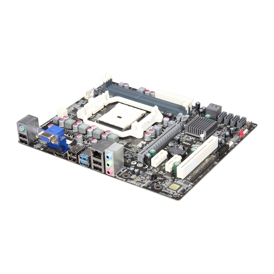
Page 9: Motherboard Components
• Supports eBLU/eDLU/eSF AP support (Warning: Microsoft .NET Framework 3.5 is required) • Supports EZ Charger Form Factor • MATX Size, 244mm x 200mm Motherboard Components Introducing the Motherboard... - Page 10 Table of Motherboard Components LABEL COMPONENTS 1. CPU Socket FM1 for AMD A series processors 2. SYS_FAN System cooling fan connector 3. CPU_FAN CPU cooling fan connector 4. DDR3_1~2 240-pin DDR3 SDRAM slots 5. ATX_POWER Standard 24-pin ATX power connector 6.
-
Page 11: Installing The Motherboard
Chapter 2 Installing the Motherboard Safety Precautions • Follow these safety precautions when installing the motherboard • Wear a grounding strap attached to a grounded device to avoid dam- age from static electricity • Discharge static electricity by touching the metal case of a safely grounded object before working on the motherboard •... -
Page 12: Checking Jumper Settings
Do not over-tighten the screws as this can stress the motherboard. Checking Jumper Settings This section explains how to set jumpers for correct configuration of the motherboard. Setting Jumpers Use the motherboard jumpers to set system configuration options. Jumpers with more than one pin are numbered. -
Page 13: Checking Jumper Settings
Checking Jumper Settings The following illustration shows the location of the motherboard jumpers. Pin 1 is labeled. Name Type Description Setting (default) 1-2: NORMAL 2-3: CLEAR CLR_CMOS 3-pin Clear CMOS Before clearing the CLR_CMOS CMOS, make sure to turn off the system. To avoid the system unstability after clearing CMOS, we recommend users to enter the main BIOS setting page to “Load Default Settings”... -
Page 14: Installing Hardware
Installing Hardware Installing the Processor Caution: When installing a CPU heatsink and cooling fan make sure that you DO NOT scratch the motherboard or any of the surface-mount resis- tors with the clip of the cooling fan. If the clip of the cooling fan scrapes across the motherboard, you may cause serious damage to the motherboard or its components. -
Page 15: Installing Memory Modules
CPU Installation Procedure The following illustration shows CPU installation components. Install your CPU. Pull up the lever away from the socket and lift up to 90-degree angle. Locate the CPU cut edge (the corner with the pin hold noticeably missing). Align and insert the CPU correctly. -
Page 16: Installation Procedure
Installation Procedure Refer to the following to install the memory modules. This motherboard supports unbuffered DDR3 SDRAM only. Push the latches on each side of the DIMM slot down. Align the memory module with the slot. The DIMM slots are keyed with notches and the DIMMs are keyed with cutouts so that they can only be installed correctly. -
Page 17: Expansion Slots
Expansion Slots Installing Add-on Cards The slots on this motherboard are designed to hold expansion cards and connect them to the system bus. Expansion slots are a means of adding or enhancing the motherboard’s features and capabilities. With these efficient facilities, you can in- crease the motherboard’s capabilities by adding hardware that performs tasks that are not part of the basic system. - Page 18 Follow these instructions to install an add-on card: Remove a blanking plate from the system case corresponding to the slot you are going to use. Install the edge connector of the add-on card into the expansion slot. Ensure that the edge connector is correctly seated in the slot. Secure the metal bracket of the card to the system case with a screw.
-
Page 19: Connecting Optional Devices
Connecting Optional Devices Refer to the following for information on connecting the motherboard’s optional devices: SATA1~6: Serial ATA connectors These connectors are used to support the new Serial ATAIII devices for the highest data transfer rates (6.0 Gb/s), simpler disk drive cabling and easier PC assembly. It doubles the transfer rate of current SATA 3.0Gb/s interface. - Page 20 F_USB1~2: Front Panel USB 2.0 headers The motherboard has six USB 2.0 ports installed on the rear edge I/O port array. Additionally, some computer cases have USB 2.0 ports at the front of the case. If you have this kind of case, use auxiliary USB 2.0 connector to connect the front- mounted ports to the motherboard.
- Page 21 USB3F: Front Panel USB 3.0 header This Motherboard implements one USB 3.0 header supporting 2 extra front USB 3.0 ports, which delivers 5Gb/s transfer rate. Signal Name Function Vbus Front Panel USB Power IntA_P1_SSRX- USB3 ICC Port1 SuperSpeed Rx- USB3 ICC Port1 SuperSpeed Rx+ IntA_P2_SSRX+ IntA_P1_SSTX- USB3 ICC Port1 SuperSpeed Tx-...
- Page 22 LPT: Onboard parallel port Header This is a header that can be used to connect to the printer, scanner or other devices. Signal Name Signal Name STROBE ERROR INIT SLCT Ground Ground Ground Ground Ground Ground BUSK Ground Ground SLCT Installing the Motherboard...
-
Page 23: Installing A Sata Hard Drive
Installing a SATA Hard Drive This section describes how to install a SATA hard drive. About SATA Connectors Your motherboard features six SATA connectors supporting a total of six drives. SATA refers to Serial ATA (Advanced Technology Attachment) is the standard inter- face for the IDE hard drives which are currently used in most PCs. -
Page 24: Connecting I/O Devices
Connecting I/O Devices The backplane of the motherboard has the following I/O ports: PS/2 mouse and Connect the PS/2 Keyboard or PS/2 Mouse to the PS/2 keyboard combo combo port. connector USB 2.0 Ports Use the USB 2.0 ports to connect USB 2.0 devices. USB 3.0 Ports Use the USB 3.0 ports to connect USB3.0 devices. -
Page 25: Connecting Case Components
Connecting Case Components After you have installed the motherboard into a case, you can begin connecting the motherboard components. Refer to the following: Connect the CPU cooling fan cable to CPU_FAN. Connect the standard power supply connector to ATX_POWER. Connect the case switches and indicator LEDs to the F_PANEL. Connect the system cooling fan connector to SYS_FAN. - Page 26 Connecting 4-pin power cable The ATX12V4P power connector is used to provide power to the CPU. When installing 4-pin power cable, the latches of power cable and the ATX12V4P match perfectly. 4-pin power cable CPU_FAN: Cooling FAN Power Connector Signal Name Function System Ground +12V...
- Page 27 ATX12V: ATX 12V Power Connector Signal Name Ground Ground +12V +12V SPK: Internal speaker Signal Name Signal Installing the Motherboard...
-
Page 28: Front Panel Header
Front Panel Header The front panel header (F_PANEL) provides a standard set of switch and LED headers commonly found on ATX or Micro ATX cases. Refer to the table below for informa- tion: Signal Function Signal Function HD_LED_P Hard disk LED (+) 2 FP PWR/SLP *MSG LED (+) HD_LED_N Hard disk LED (-) FP PWR/SLP *MSG LED (-) -
Page 29: Using Bios
Chapter 3 Using BIOS About the Setup Utility The computer uses the latest “American Megatrends Inc. ” BIOS with support for Windows Plug and Play. The CMOS chip on the motherboard contains the ROM setup instructions for configuring the motherboard BIOS. The BIOS (Basic Input and Output System) Setup Utility displays the system’s configuration status and provides you with options to set system parameters. -
Page 30: Resetting The Default Cmos Values
Press the delete key to access BIOS Setup Utility. Above image is for reference only, for details please refer to actual image. Resetting the Default CMOS Values When powering on for the first time, the POST screen may show a “CMOS Settings Wrong”... -
Page 31: Bios Navigation Key
In this manual, submenu items are denoted by an icon The default BIOS setting for this motherboard apply for most conditions with optimum performance. We do not suggest users change the default values in the BIOS setup and take no responsibility to any damage caused by changing the BIOS settings. -
Page 32: Main Menu
Main Menu This menu shows the information of BIOS and enables you to set the system language, date and time. Main Advanced Chipset M.I.B III Boot Security Exit Choose the system default BIOS Information language System Language English System Date Tue 01/01/2008 System Time 16:52:28... -
Page 33: Advanced Menu
Advanced Menu The Advanced menu items allow you to change the settings for the CPU and other system. Main Advanced Chipset M.I.B III Boot Security Exit LAN Configuration Parameters LAN Configuration PC Health Status Power Management Setup ACPI Settings CPU Configuration SATA Configuration : Select Screen USB Configuration... -
Page 34: Pc Health Status
PC Health Status On motherboards support hardware monitoring, this item lets you monitor the parameters for critical voltages, temperatures and fan speeds. Main Advanced Chipset M.I.B III Boot Security Exit Smart Fan Function CPU Tct1 CPU FAN SYS FAN 4672 RPM CPU Vcore +1.200 V DIMM Voltage... - Page 35 Smart Fan Mode (Normal) This item allows you to select the fan mode (Normal, Quiet, Silent, or Manual) for a better operation environment. If you choose Normal mode, the fan speed will be auto adjusted depending on the CPU temperature. If you choose Quiet mode, the fan speed will be auto minimized for quiet environment.
-
Page 36: Power Management Setup
Power Management Setup This page sets up some parameters for system power management operation. Main Advanced Chipset M.I.B III Boot Security Exit About Resume by Ring Power Management Setup Resume By RING Disabled Resume By PME Disabled Resume By USB 1.x/2.0 (S3) Disabled Resume By PS2 KB (S3) Disabled... -
Page 37: Acpi Configuration
ACPI Configuration The item in the menu shows the highest ACPI sleep state when the system enters suspend. Aptio Setup Utility - Copyright (C) 2011 American Megatrends, Inc. Main Advanced Chipset M.I.B III Boot Security Exit Select the highest ACPI ACPI Setting sleep state the system will enter when the... -
Page 38: Cpu Configuration
CPU Configuration Scroll to this item and press <Enter> to view the following screen: Main Advanced Chipset M.I.B III Boot Security Exit CPU Configuration Disabled for Windows XP Node0: AMD Engineering Sample Max Speed: 2133 MHZ Intended Speed: 2133 MHZ Microcode Patch Level: 300000f --------- Cache per Core --------- L1 Instruction Cache: 64 KB/2-way... -
Page 39: Sata Configuration
SATA Configuration Use this item to show the mode of serial SATA configuration options. Main Advanced Chipset M.I.B III Boot Security Exit SATA Configuration Serial-ATA Controller Enabled SATA Mode SATA Port1 WDC WD5000AAKX (500.1 SATA Port2 Not Present SATA Port3 Not Present SATA Port4 Not Present... -
Page 40: Usb Configuration
USB Configuration Scroll to this item and press <Enter> to view the following screen: Main Advanced Chipset M.I.B III Boot Security Exit USB Configuration All USB Devices Enabled Legacy USB Support Enabled : Select Screen /Click: Select Item Enter/Dbl Click : Select +/- : Change Opt. -
Page 41: Super Io Configuration
Super IO Configuration Scroll to this item and press <Enter> to view the following screen: Main Advanced Chipset M.I.B III Boot Security Exit Set Parameters of Serial Super IO Configuration Port 0 (COMA) Serial Port 0 Configuration Parallel Port Configuration : Select Screen /Click: Select Item Enter/Dbl Click : Select... - Page 42 Parallel Port Configuration This item shows the information of the super IO chip. Main Advanced Chipset M.I.B III Boot Security Exit Parallel Port Configuration Enable or Disable Parallel Port (LPT/LPTE) Parallel Port Enabled Device Settings IO=378h; IRQ=5; Change Settings Auto : Select Screen Device Mode Standard and Bi-di ...
-
Page 43: Chipset Menu
Chipset Menu The chipset menu items allow you to change the settings for the North Bridge chipset, South Bridge chipset and other system. Main Advanced Chipset M.I.B III Boot Security Exit North Bridge North Bridge Parameters South Bridge : Select Screen /Click: Select Item Enter/Dbl Click : Select +/- : Change Opt. - Page 44 South Bridge Scroll to this item and press <Enter> to view the following screen. Main Advanced Chipset M.I.B III Boot Security Exit Enabled/Disabled Azalia SB Chipset Configuration HD Audio Azalia HD Audio Enabled Azalia Internal HDMI codec Enabled Restore AC Power Loss Power Off Case Open Warning Disabled...
-
Page 45: M.i.b.iii (Mb Intelligent Bios Iii) Menu
M.I.B.III (MB Intelligent BIOS III) Menu This page enables you to set the clock speed and system bus for your system. The clock speed and system bus are determined by the kind of processor you have installed in your system. Main Advanced Chipset... -
Page 46: Boot Menu
Boot Menu This page enables you to set the keyboard NumLock state. Main Advanced Chipset M.I.B III Boot Security Exit Boot Configuration Windows 7 or other OS: Operation System Select Windows7 or other OS Boot policy for Legacy OS Launch PXE OpROM Disabled Launch Storage OpROM Enabled... - Page 47 Hard Disk / CD/DVD ROM / USB Floppy / USB CD/DVD ROM / USB HardDisk / USB Flash / Network Boot Drive Priorities These items enable you to specify the sequence of loading the operating system. Press <Enter> to see the submenu. CSM parameters OpROM execution, boot options filter,etc.
- Page 48 Hard Disk / CD/DVD ROM / USB Floppy / USB CD/DVD ROM / USB HardDisk / USB Flash / Network Boot Drive Priorities These items enable you to specify the sequence of loading the operating system. Press <Enter> to see the submenu. CSM parameters OpROM execution, boot options filter,etc.
-
Page 49: Security Menu
Security Menu This page enables you to set setup administrator password and user password. Main Advanced Chipset M.I.B III Boot Security Exit Administrator Password Status Not Install Secure Boot mode selector. ‘Standard’ -fixed Secure User Password Status Not Install boot policy, ‘Custom’ - changeable Image Administrator Password Execution policy and Secure... - Page 50 Image Execution Policy Scroll to this item to view the following screen: Main Advanced Chipset M.I.B III Boot Security Exit Internal FV Always Execute Image Execution Policy per Option ROM Deny Execute device path on Security Removable Media Deny Execute Violation.
- Page 51 Key Management Scroll to this item to view the following screen: Main Advanced Chipset M.I.B III Boot Security Exit Default Key Provisioning Disabled Force OEM default Secure Manage All Factory Keys (PK, KEK, DB, DBX) Boot Keys if System is in Install default Secure Boot keys Setup Mode.
-
Page 52: Exit Menu
Exit Menu This page enables you to exit system setup after saving or without saving the changes. Main Advanced Chipset M.I.B III Boot Security Exit Save Changes and Exit Exit system setup after Discard Changes and Exit saving the changes. Save Changes and Reset Discard Changes and Reset Save Options... -
Page 53: Updating The Bios
Updating the BIOS You can download and install updated BIOS for this motherboard from the manufacturer’s Web site. New BIOS provides support for new peripherals, improve- ments in performance, or fixes for known bugs. Install new BIOS as follows: If your motherboard has a BIOS protection jumper, change the setting to allow BIOS flashing. - Page 54 Memo Using BIOS...
-
Page 55: Using The Motherboard Software
C l i c k t h e “Setup” Click the “ Utilities” button to select and button to select and software install ECS Intelligent installation program. Utility. Running Setup Follow these instructions to install device drivers and software for the motherboard: Click Setup. - Page 56 Click Next. The following screen appears: Check the box next to the items you want to install. The default options are recommended. Click Next to run the Installation Wizard. An item installation screen appears: Follow the instructions on the screen to install the items. Drivers and software are automatically installed in sequence.
-
Page 57: Manual Installation
README.DOC) for information on installing the driver or software for your oper- ating system. ECS Utility Software (Intelligent EZ Utility) ECS Intelligent EZ Utility provides friendly interfaces under Windows O.S, which makes your computing more easily and conveniently. These software(s) are subject to change at anytime without prior notice. Please refer to the support disk for available software. - Page 58 Just select the one you prefer and start to download and install the drivers. eBLU ECS eBLU utility makes BIOS update faster and easier. eBLU will list the latest BIOS with a default check-mark. Click”install” button to install. Microsoft .NET Framework 3.5 is required.
-
Page 59: Crossfire Technology (Amd Dual Graphics) Support
Chapter 5 ® CrossFire Technology (AMD Dual Graphics) Support ® CrossFire Technology ® The CrossFire technology provides significant display performance boost to AMD- based systems by inserting the external PCI Express graphics card and enabling both the discrete GPU and the AMD A75 graphics core to render simultaneously in Hybrid CrossFire mode. - Page 60 3. Set the CrossFire in Advanced Menu to Enabled. Then press F4 to save the configuration and exit the BIOS. Main Advanced Chipset M.I.B III Boot Security Exit CrossFire: Output is IGD North Chipset Configuration Video IGD Memory Auto Initate Graphic Adapter CrossFire Enabled :Select Screen...
- Page 61 Please reference latest AMD Dual Graphics? Technology Graphic Card support list on AMD official website and subject to change without no- tice. 5. Enter AMD VISION Engine Control Center, you can see the option of CrossFire ® click it and select Enable CrossFire , then CrossFire starts.
- Page 62 Recommendation 1.The APU in the A75 platform delivers a discrete-class of graphics performance and enables leading GPU compute capability -Adding a discrete GPU is optional to extend graphics and GPU compute capacity ® 2.For optimal performance uplift, AMD recommends Dual Graphics (CrossFire Technology) combinations of -A4 and Discrete GPU model Radeon HD6450 -A6 and Discrete GPU model Radeon HD6570...
-
Page 63: Setting Up Amd A75 Raid Configuration
Chapter 6 Setting Up AMD A75 RAID Configuration Setting Up a bootable RAID Array This section explains how to configure a bootable AMD RAID array. Setting Up the BIOS 1. Start your computer, then press Delete to enter the BIOS setup. The BIOS CMOS Setup Utility screen appears. -
Page 64: Entering The Raid Bios Setup
4. Press F4 to save the configuration and exit. The PC reboots. 5. Enter the RAID BIOS Setup by pressing Ctrl-F when prompted, and proceed to set up the AMD RAID BIOS as described in the next section. Configuring the AMD RAID BIOS (Windows XP Installation) The AMD RAID BIOS set up lets you choose the RAID type and which hard drives you want to make part of the array. - Page 65 Select [2], then select LD 1 in the following page. The Define LD Menu screen appears (Figure 1.4). FastBuild (tm) Utility (c) 2006 ATI Technology, Inc. [ Define LD Menu ] LD No RAID Mode Total Drv LD 1 RAID 0 Stripe Block : 64 KB Past Init :...
- Page 66 Assigning the Disks 1. Select the Assignment to Y to designate a free disk to be used as a RAID array disk. Figure 1.5 illustrates the Define a New Array screen after two disks have been assigned as RAID 0 array disks. FastBuild (tm) Utility (c) 2006 ATI Technology, Inc.
- Page 67 Press ESC to exit. The Main Menu screen appears (Figure 1.7). FastBuild (tm) Utility (c) 2006 ATI Technology, Inc. [ Main Menu ] View Drive Assignments....[ 1 ] Define LD..........[ 2 ] Define LD..........[ 3 ] System is going to REBOOT! Controller Configuration....[ 4 ] Are You Sure? Y - Reboot / Any Key - Back...
-
Page 68: Installing The Raid Drivers
Installing the RAID Drivers Your system may come with a Windows install CD that already includes AMD RAID drivers. If so, then this section is not relevant. If that is not the case (or you are trying to install a new version of Windows), then you will need an AMD RAID driver F6 install floppy. - Page 69 The following Windows Setup screen appears: Windows Setup --------- You have chosen to configure a SCSI Adapter for use with windows£¬ using a device support disk provided bu an adapter manufacturer. Select the SCSI Adapter you want from the following list, or press ESC to return to the previous screen.
- Page 70 Memo Setting Up AMD A75 RAID Configuration...
-
Page 71: Trouble Shooting
Chapter 7 Trouble Shooting Start up problems during assembly After assembling the PC for the first time you may experience some start up problems. Before calling for technical support or returning for warranty, this chapter may help to address some of the common questions using some basic troubleshooting tips. -
Page 72: Start Up Problems After Prolong Use
2. From the BIOS setting, try to disable the Smartfan function to let the fan run at default speed. Doing a Load Optimised Default will also disable the Smartfan. Start up problems after prolong use After a prolong period of use your PC may experience start up problems again. This may be caused by breakdown of devices connected to the motherboard such as HDD, CPU fan, etc. - Page 74 Memo Trouble Shooting...
Need help?
Do you have a question about the A75F-M2 and is the answer not in the manual?
Questions and answers