Table of Contents
Advertisement
Advertisement
Table of Contents

Related Manuals for ECS A770M-A


Summary of Contents for ECS A770M-A
- Page 3 Preface Copyright This publication, including all photographs, illustrations and software, is protected under international copyright laws, with all rights reserved. Neither this manual, nor any of the material contained herein, may be reproduced without written consent of the author. Version 1.0C Disclaimer The information in this document is subject to change without notice.
-
Page 4: Declaration Of Conformity
Declaration of Conformity This device complies with part 15 of the FCC rules. Operation is subject to the following conditions: • This device may not cause harmful interference, and • This device must accept any interference received, including interfer- ence that may cause undesired operation. Canadian Department of Communications This class B digital apparatus meets all requirements of the Canadian Interference- causing Equipment Regulations. -
Page 5: Table Of Contents
T T T T T ABLE OF CONTENTS ABLE OF CONTENTS ABLE OF CONTENTS ABLE OF CONTENTS ABLE OF CONTENTS Preface Chapter 1 Introducing the Motherboard Introduction....................1 Features....................2 Motherboard Components..............4 Chapter 2 7 7 7 7 7 Installing the Motherboard Safety Precautions................7 Choosing a Computer Case..............7 Installing the Motherboard in a Case..........7... - Page 6 Integrated Peripherals..............34 Power Management Setup............35 PCI/PnP Configurations..............36 PC Health Status................37 Frequency/Voltage Control............38 Load Default Settings..............39 Supervisor Password..............39 User Password................40 Save & Exit Setup ................41 Exit Without Saving...............41 Chapter 4 43 43 43 43 Using the Motherboard Software About the Software CD-ROM............43 Auto-installing under Windows 2000/XP/Vista......43 Running Setup................44 Manual Installation................48...
-
Page 7: Introducing The Motherboard
Chapter 1 Introducing the Motherboard Introduction Thank you for choosing the A770M-A motherboard. This motherboard is a high performance, enhanced function motherboard that supports socket for AMD Phenom processor (socket AM2+)/AMD Athlon 64 X2 Dual-Core/Athlon 64/Sempron processors for high-end business or personal desktop markets. -
Page 8: Features
Feature Processor This motherboard uses a socket AM2+/AM2 that carries the following features: • Accommodates AMD Phenom processor (socket AM2+) AMD Athlon 64 X2 Dual-Core/Athlon 64/Sempron processors • Supports HyperTransport (HT) 3.0 interface speeds HyperTransport Technology is a point-to-point link between two devices, it enables integrated circuits to exchange information at much higher speeds than currently available interconnect technologies. - Page 9 Onboard LAN (Optional) The onboard LAN provides the following features: • Integrated Fast Ethernet Controller for PCI Express Applica- tions • Integrated 10/100 transceiver • Wake-on-LAN and remote wake-up support • Integrated Gigabit Ethernet Controller for PCI Express Applica- tions •...
-
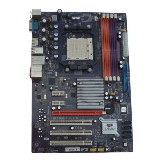
Page 10: Motherboard Components
Motherboard Components Introducing the Motherboard... - Page 11 Table of Motherboard Components LABEL COMPONENTS Socket for AMD Phenom procssor (socket AM2+)/AMD Athlon 1. CPU Socket 64 X2 Dual-Core/Athlon 64/Sempron processors CPU cooling fan connector 2. CPU_FAN1 240-pin DDR2 SDRAM slots 3. DRR2_1~4 4. ATX_POWER1 Standard 24-pin ATX power connector 5.
- Page 12 Memo Introducing the Motherboard...
-
Page 13: Installing The Motherboard
Chapter 2 Installing the Motherboard Safety Precautions • Follow these safety precautions when installing the motherboard • Wear a grounding strap attached to a grounded device to avoid dam- age from static electricity • Discharge static electricity by touching the metal case of a safely grounded object before working on the motherboard •... -
Page 14: Checking Jumper Settings
Do not over-tighten the screws as this can stress the motherboard. Checking Jumper Settings This section explains how to set jumpers for correct configuration of the motherboard. Setting Jumpers Use the motherboard jumpers to set system configuration options. Jumpers with more than one pin are numbered. -
Page 15: Checking Jumper Settings
Checking Jumper Settings The following illustration shows the location of the motherboard jumpers. Pin 1 is labeled. Jumper Settings Jumper Type Description Setting (default) 1-2: NORMAL 2-3: CLEAR CMOS CLR_CMOS 3-pin Clear CMOS Before clearing the CMOS, make sure to CLR_CMOS turn off the system. -
Page 16: Connecting Case Components
Connecting Case Components After you have installed the motherboard into a case, you can begin connecting the motherboard components. Refer to the following: Connect the CPU cooling fan cable to CPU_FAN1. Connect the standard power supply connector to ATX_POWER1. Connect the case speaker cable to SPK. Connect the case switches and indicator LEDs to the F_PANEL. -
Page 17: Atx 24-Pin Power Connector
CPU_FAN1: Cooling FAN Power Connector Function Signal Name System Ground +12V Power +12V Sense Sensor CPU FAN control Users please note that the fan connector supports the CPU cooling fan of 1.1A~2.2A (26.4W max.) at +12V. ATX_POWER1: ATX 24-pin Power Connector Signal Name Signal Name +3.3V... -
Page 18: Front Panel Header
Front Panel Header The front panel header (F_PANEL) provides a standard set of switch and LED headers commonly found on ATX or Micro ATX cases. Refer to the table below for information: Signal Function Signal Function HD_LED_P Hard disk LED (+) 2 FP PWR/SLP *MSG LED (+) HD_LED_N Hard disk LED (-) FP PWR/SLP *MSG LED (-) -
Page 19: Installing Hardware
Installing Hardware Installing the Processor Caution: When installing a CPU heatsink and cooling fan make sure that you DO NOT scratch the motherboard or any of the surface- mount resistors with the clip of the cooling fan. If the clip of the cooling fan scrapes across the motherboard, you may cause serious damage to the motherboard or its components. -
Page 20: Installing Memory Modules
CPU Installation Procedure The following illustration shows CPU installation components. Install your CPU. Pull up the lever away from the socket and lift up to 90-degree angle. Locate the CPU cut edge (the corner with the pin hold noticeably missing). Align and insert the CPU correctly. -
Page 21: Installation Procedure
Installation Procedure Refer to the following to install the memory modules. This motherboard supports unbuffered DDR2 SDRAM only. Push the latches on each side of the DIMM slot down. Align the memory module with the slot. The DIMM slots are keyed with notches and the DIMMs are keyed with cutouts so that they can only be installed correctly. - Page 22 Table A: DDR2 (memory module) QVL (Qualified Vendor List) The following DDR2 800/667/533/400 memory modules have been tested and quali- fied for use with this motherboard. Type Size Vendor Module Nam e Hynix 256 MB HYMP532U646-E3 AA DDR2 400 Nanya NT512T64U88A0F-5A 512 MB 256 MB...
-
Page 23: Installing A Hard Disk Drive/Cd-Rom/Sata Hard Drive
Type Size Vendor Module Nam e Infineon 256 MB HYS64T32000HU-25F-B A-DATA M2OAD6G3H3160I1E53 Aeneon AET660UD00-25DB98X Apacer AU512E800C5KBGC 512 MB APOGEE AU51082-800P505 Infineon HYS64T64000HU-25F-B Nanya NT512T64U88B0BY-25C DDR2 800 AL6E8E63H-8E1 APOGEE AU1G082-800P000 Infineon HYS64T128020HU-25F-B Kingston KHX6400D2ULK2/1G 1 GB Nanya NT1GT64U8HB0BY-25C AL7E8E63H-8E1 UMAX 53016042-7100B Mem ory Type Size... - Page 24 IDE: IDE Connector This motherboard supports four high data transfer SATA ports with each runs up to 3.0 Gb/s. To get better system performance, we recommend users connect the CD-ROM to the IDE channel, and set up the hard dives on the SATA ports. IDE devices enclose jumpers or switches used to set the IDE device as MASTER or SLAVE.
-
Page 25: Installing Add-On Cards
Installing Add-on Cards The slots on this motherboard are designed to hold expansion cards and connect them to the system bus. Expansion slots are a means of adding or enhancing the motherboard’s features and capabilities. With these efficient facilities, you can in- crease the motherboard’s capabilities by adding hardware that performs tasks that are not part of the basic system. - Page 26 Follow these instructions to install an add-on card: Remove a blanking plate from the system case corresponding to the slot you are going to use. Install the edge connector of the add-on card into the expansion slot. Ensure that the edge connector is correctly seated in the slot. Secure the metal bracket of the card to the system case with a screw.
-
Page 27: Connecting Optional Devices
Connecting Optional Devices Refer to the following for information on connecting the motherboard’s optional devices: F_AUDIO: Front Panel Audio header This header allows the user to install auxiliary front-oriented microphone and line- out ports for easier access. Signal Name Signal Name Signal Name Function PORT 1L... - Page 28 F_USB1~2: Front Panel USB headers The motherboard has six USB ports installed on the rear edge I/O port array. Addi- tionally, some computer cases have USB ports at the front of the case. If you have this kind of case, use auxiliary USB connector to connect the front-mounted ports to the motherboard.
-
Page 29: Connecting I/O Devices
Connecting I/O Devices The backplane of the motherboard has the following I/O ports: PS2 Mouse Use the upper PS/2 port to connect a PS/2 pointing device. PS2 Keyboard Use the lower PS/2 port to connect a PS/2 keyboard. ESATA Port Use this port to connect to an external SATA box or a Serial ATA portmultiplier. - Page 30 Memo Installing the Motherboard...
-
Page 31: Using Bios
Chapter 3 Using BIOS About the Setup Utility The computer uses the latest “American Megatrends Inc.” BIOS with support for Windows Plug and Play. The CMOS chip on the motherboard contains the ROM setup instructions for configuring the motherboard BIOS. The BIOS (Basic Input and Output System) Setup Utility displays the system ’... -
Page 32: Bios Navigation Keys
Press DEL to enter SETUP Press the delete key to access the BIOS Setup Utility. CMOS Setup Utility -- Copyright (C) 1985-2007, American Megatrends, Inc. Standard CMOS Setup Frequency/Voltage Control Advanced Setup Load Default Settings Advanced Chipset Setup Supervisor Password Integrated Peripherals User Password Power Management Setup... -
Page 33: Updating The Bios
Updating the BIOS You can download and install updated BIOS for this motherboard from the manufacturer’s Web site. New BIOS provides support for new peripherals, improve- ments in performance, or fixes for known bugs. Install new BIOS as follows: Create a bootable system disk. (Refer to Windows online help for information on creating a bootable system disk.) Download the Flash Utility and new BIOS file from the manufacturer’s Web site. -
Page 34: Standard Cmos Features
Standard CMOS Setup This option displays basic information about your system. CMOS Setup Utility -- Copyright (C) 1985-2007, American Megatrends, Inc. Standard CMOS Setup Date Wed 09/26/2007 Help Item Time 02 : 45 : 33 Use [ENTER], [TAB] Primary IDE Master Not Detected or [SHIFT-TAB] to Primary IDE Slave... -
Page 35: Advanced Bios Features
Type (Auto) Use this item to configure the type of the IDE device that you specify. If the feature is enabled, it will enhance hard disk performance by reading or writing more data during each transfer LBA/Large Mode (Auto) Use this item to set the LAB/Large mode to enhance hard disk performance by optimizing the area the hard disk is visited each time. - Page 36 CPU Virtualization (Enabled) Hardware Virtualization Technology enables processor feature for running multiple simultaneous Virtual Machines allowing specialized software applications to run in full isolation of each other. AMD C&Q (Enabled) This item helps the system to lower the frequency when CPU idles. When the frequency decreases, the temperature will drop automatically as well.
-
Page 37: Advanced Chipset Features
Advanced Chipset Setup This page sets up more advanced information about your system. Handle this page with caution. Any changes can affect the operation of your computer. CMOS Setup Utility - Copyright (C) 1985-2007, American Megatrends, Inc. Advanced Chipset Setup Help Item HT Configuration Press Enter... - Page 38 HT3 Protocol Checker (Auto) This item is used to set the HT3 Protocol Checker. NB Transmitter Attenuation (00) This item is used to set the Northbridge transmitter attenuation. CPU Transmitter Attenuation (00) This item is used to set the CPU transmitter attenuation. NB &...
- Page 39 Unganged Mode support (Auto) This item is used to set the unganged mode support. Power Down Enable (Enabled) When in power down mode, if all pages of the DRAMs associated with a CKE pin are closed, then these parts are placed in power down mode. Only pre-charge power down mode is supported, not active power down mode.
-
Page 40: Integrated Peripherals
Integrated Peripherals This page sets up some parameters for peripheral devices connected to the system. CMOS Setup Utility - Copyright (C) 1985-2007, American Megatrends, Inc. Integrated Peripherals Onboard IDE Controller Primary Help Item Onboard SATA Mode Enabled SATA Configuration DISABLED: disables the Onboard AUDIO Function Enabled integrated IDE... -
Page 41: Power Management Setup
Power Management Setup This page sets up some parameters for system power management operation. CMOS Setup Utility - Copyright (C) 1985-2007, American Megatrends, Inc. Power Management Setup Help Item ACPI Suspend Type S3 (STR) Soft-off by PWR-BTTN Instant Off PWRON After PWR-Fail Power Off Select the ACPI state used for... -
Page 42: Pci/Pnp Configurations
Resume By PS2 MS (S3) (Disabled) This item enables or disables you to allow mouse activity to awaken the system from power saving mode. Resume By RTC Alarm (Disabled) The system can be turned off with a software command. If you enable this item, the system can automatically resume at a fixed time based on the system’s RTC (realtime clock). -
Page 43: Pc Health Status
PC Health Status On motherboards support hardware monitoring, this item lets you monitor the parameters for critical voltages, temperatures and fan speeds. CMOS Setup Utility - Copyright (C) 1985-2007, American Megatrends, Inc. PC Health Status Help Item -=- System Hardware Monitor -=- Smart Fan Function Press Enter Shutdown Temperature... -
Page 44: Frequency/Voltage Control
DeltaT1 (+3) This item specifies the range that controls CPU temperature and keeps it from going so high or so low when smart fan works. SMART Fan Slope PWM value (4 PWM value/°C) This item is used to set the Slope Select PWM of the smart fan. Press <Esc>... -
Page 45: Load Default Settings
Auto Detect DIMM/PCI Clk (Enabled) When this item is enabled, BIOS will disable the clock signal of free DIMM/PCI slots. Spread Spectrum (Disabled) If you enable spread spectrum, it can significantly reduce the EMI (Electro-Magnetic Interference) generated by the system. CPU Over-clocking Func. -
Page 46: User Password
Supervisor Password (Not Installed) This item indicates whether a supervisor password has been set. If the password has been installed, Installed displays. If not, Not Installed displays. Change Supervisor Password (Press Enter) You can select this option and press <Enter> to access the sub menu. You can use the sub menu to change the supervisor password. -
Page 47: Save & Exit Setup
Save & Exit Setup Highlight this item and press <Enter> to save the changes that you have made in the Setup Utility and exit the Setup Utility. When the Save and Exit dialog box appears, select [OK] to save and exit, or select [Cancel] to return to the main menu. Exit Without Saving Highlight this item and press <Enter>... - Page 48 Memo Using BIOS...
-
Page 49: Using The Motherboard Software
Chapter 4 Using the Motherboard Software About the Software CD-ROM The support software CD-ROM that is included in the motherboard package contains all the drivers and utility programs needed to properly run the bundled products. Below you can find a brief description of each software program, and the location for your motherboard version. -
Page 50: Running Setup
Setup Tab Setup Click the Setup button to run the software installation program. Select from the menu which software you want to install. Browse CD The Browse CD button is the standard Windows command that allows you to open Windows Explorer and show the contents of the support CD. - Page 51 Click Next. The following screen appears: Check the box next to the items you want to install. The default options are recom- mended. Click Next run the Installation Wizard. An item installation screen appears: Follow the instructions on the screen to install the items. 1.
- Page 52 Method 1. Run Reboot Setup Windows Vista will block startup programs by default when installing drivers after the system restart. You must select taskbar icon Run Blocked Program and run Reboot Setup to install the next driver, until you finish all drivers installation. Method 2.
- Page 53 Select Classic View. Set User Account. Select Turn User Account Control on or off and press Continue. Using the Motherboard Software...
-
Page 54: Manual Installation
Disable User Account Control (UAC) to help protect your computer item and press OK, then press Restart Now. Then you can restart your computer and continue to install drivers without running blocked programs. Manual Installation Insert the CD in the CD-ROM drive and locate the PATH.DOC file in the root directory.
Need help?
Do you have a question about the A770M-A and is the answer not in the manual?
Questions and answers