Table of Contents
Advertisement
Advertisement
Table of Contents

Related Manuals for ECS A780GM-M3


Summary of Contents for ECS A780GM-M3
- Page 3 Preface Copyright This publication, including all photographs, illustrations and software, is protected under international copyright laws, with all rights reserved. Neither this manual, nor any of the material contained herein, may be reproduced without written consent of the author. Version 1.0 Disclaimer The information in this document is subject to change without notice.
-
Page 4: Declaration Of Conformity
Declaration of Conformity This device complies with part 15 of the FCC rules. Operation is subject to the following conditions: • This device may not cause harmful interference, and • This device must accept any interference received, including interfer- ence that may cause undesired operation. Canadian Department of Communications This class B digital apparatus meets all requirements of the Canadian Interference- causing Equipment Regulations. -
Page 5: Table Of Contents
T T T T T ABLE OF CONTENTS ABLE OF CONTENTS ABLE OF CONTENTS ABLE OF CONTENTS ABLE OF CONTENTS Preface Chapter 1 Introducing the Motherboard Introduction....................1 Features....................2 Motherboard Components..............4 Chapter 2 7 7 7 7 7 Installing the Motherboard Safety Precautions.................7 Choosing a Computer Case..............7 Installing the Motherboard in a Case..........7... - Page 6 Integrated Peripherals..............35 Power Management Setup.............37 PCI/PnP Setup................38 PC Health Status................39 Frequency/Voltage Control............41 Load Default Settings..............42 Supervisor Password..............42 User Password................43 Save & Exit Setup .................43 Exit Without Saving...............43 45 45 45 45 Chapter 4 Using the Motherboard Software About the Software CD-ROM............45 Auto-installing under Windows XP/Vista........45 Running Setup................46 Manual Installation................50...
-
Page 7: Introducing The Motherboard
Chapter 1 Introducing the Motherboard Introduction Thank you for choosing the A780GM-M3 motherboard. This motherboard is a high performance, enhanced function motherboard that supports socket for Phenom processor (socket AM2+)/Athlon 64 X2 Dual-Core/Athlon Sempron processors for high-end business or personal desktop markets. -
Page 8: Features
Feature Processor This motherboard uses a socket AM2+/AM2 that carries the following features: • Accommodates AMD Phenom processor (socket AM2+) AMD Athlon 64X2 Dual-Core/Athlon 64/Sempron™ processors • Supports HyperTransport (HT) 3.0 interface speeds HyperTransport Technology is a point-to-point link between two devices, it enables integrated circuits to exchange information at much higher speeds than currently available interconnect technologies. -
Page 9: Bios Firmware
Audio (optional) The onboard Audio provides either of the following features: • 5.1 Channel High Definition Audio Codec • DACs support 96K/48K/44.1KHz sample rate • Power support: Digital:3.3V; Analog:5.0V • and Tru Surround from SRS • Provides single ended CD input with DRM solutions and legacy OS issues •... -
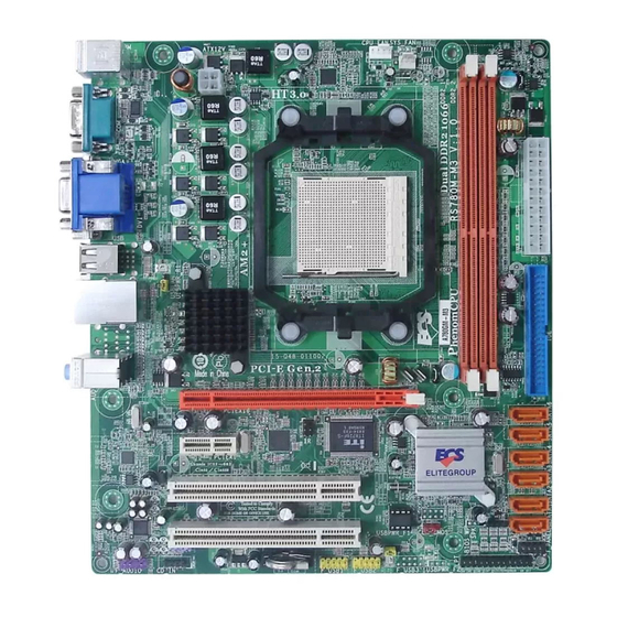
Page 10: Motherboard Components
Motherboard Components Introducing the Motherboard... - Page 11 Table of Motherboard Components LABEL CO MPO NENTS Socket for AMD Phenom processor (socket AM2+)/AMD Athlon 1. CPU Socket 64 X2 Dual-Core/Athlon 64/Sempron processors 2. CPU_FAN CPU cooling fan connector 3. SYS_FAN System cooling fan connector 4. DDR2_1~2 240-pin DDR2 SDRAM slots 5.
- Page 12 Memo Introducing the Motherboard...
-
Page 13: Installing The Motherboard
Chapter 2 Installing the Motherboard Safety Precautions • Follow these safety precautions when installing the motherboard • Wear a grounding strap attached to a grounded device to avoid dam- age from static electricity • Discharge static electricity by touching the metal case of a safely grounded object before working on the motherboard •... -
Page 14: Checking Jumper Settings
Do not over-tighten the screws as this can stress the motherboard. Checking Jumper Settings This section explains how to set jumpers for correct configuration of the motherboard. Setting Jumpers Use the motherboard jumpers to set system configuration options. Jumpers with more than one pin are numbered. -
Page 15: Checking Jumper Settings
Checking Jumper Settings The following illustration shows the location of the motherboard jumpers. Pin 1 is labeled. Jumper Settings Jumper Type Description Setting (default) 1-2: NORMAL 2-3: CLEAR CLR_CMOS 3-pin CLEAR CMOS Before clearing the CMOS, make sure to CLR_CMOS turn the system off. -
Page 16: Installing Hardware
Installing Hardware Installing the Processor Caution: When installing a CPU heatsink and cooling fan make sure that you DO NOT scratch the motherboard or any of the surface- mount resistors with the clip of the cooling fan. If the clip of the cooling fan scrapes across the motherboard, you may cause serious damage to the motherboard or its components. -
Page 17: Cpu Installation Procedure
CPU Installation Procedure The following illustration shows CPU installation components. Unhook the locking lever of the CPU socket. Pull the locking lever away from the socket and raising it to the upright position. Match the pin1 corner marked as the beveled edge on the CPU with the pin1 corner on the socket. -
Page 18: Installing Memory Modules
Installing Memory Modules This motherboard accommodates two memory modules. It can support two 240-pin DDR2 1066 (AM2+)/800/667/533/400. The total memory capacity is 16 GB*. DDR2 SDRAM memory module table Memory module Memory Bus DDR2 200 MHz DDR2 266 MHz DDR2 333 MHz DDR2 400 MHz... - Page 19 Table A: Unbuffered DIMM Support for Socket AM2+/AM2 CPU DRAM Speed DIMM1 DIMM2 Timing Mode DDR2-400 DDR2-400 DDR2-533 SRx16 SRx16 DDR2-533 SRx16 SRx8 SRx8 SRx16 DDR2-533 SRx8 SRx8 DDR2-533 DRx8 DRx8 DRx8 SRx16 DDR2-533 SRx16 DRx8 DRx8 SRx8 DDR2-533 SRx8 DRx8 DDR2-667 SRx16...
- Page 20 Table B: DDR2 (memory module) QVL (Qualified Vendor List) The following DDR2 1066 (AM2+)/800/667/533/400 memory modules have been tested and qualified for use with this motherboard. Type Size Vendor Module Name Samsung M37 8T3354 BZ0-CCC K 4T5116 3QB -ZCCC 256 MB DDR2 400 Samsung M378T65 53BG 0-CCC K 4T5108 3QB -GCCC...
- Page 21 Type Size Vendor Module Name Ap acer AHU51 2E80 0C5K1 C CO RS AIR CM2X1 024-6 400P RO HYS64T64 020HU-2.5-A Infineo n HYB1 8T256 80 0AF25 512 MB DDR2 800 04701 G16 CZ5U2G Infinity 047 5120 8CZ5 U2D Sync MAX U5 38H8G0 9DHL UMA X U2 S12D30 TP-8E...
-
Page 22: Expansion Slots
Expansion Slots Installing Add-on Cards The slots on this motherboard are designed to hold expansion cards and connect them to the system bus. Expansion slots are a means of adding or enhancing the motherboard’s features and capabilities. With these efficient facilities, you can in- crease the motherboard’s capabilities by adding hardware that performs tasks that are not part of the basic system. - Page 23 Follow these instructions to install an add-on card: Remove a blanking plate from the system case corresponding to the slot you are going to use. Install the edge connector of the add-on card into the expansion slot. Ensure that the edge connector is correctly seated in the slot. Secure the metal bracket of the card to the system case with a screw.
-
Page 24: Connecting Optional Devices
Connecting Optional Devices Refer to the following for information on connecting the motherboard’s optional devices: F_AUDIO: Front Panel Audio header This header allows the user to install auxiliary front-oriented microphone and line- out ports for easier access. Signal Name Signal Name Signal Name Function PORT 1L... - Page 25 SATA1~6: Serial ATA connectors These connectors are used to support the new Serial ATA devices for the highest data transfer rates (3.0 Gb/s), simpler disk drive cabling and easier PC assembly. It elimi- nates limitations of the current Parallel ATA interface. But maintains register com- patibility and software compatibility with Parallel ATA.
- Page 26 IR: Infrared header The motherboard supports an Infrared (IR) data port. Infrared ports allow the wire- less exchange of information between your computer and similarly equipped devices such as printers, laptops, Personal Digital Assistants (PDAs), and other computers. Signal Name Function Not Assigned Not assigned...
-
Page 27: Installing A Hard Disk Drive/Cd-Rom/Sata Hard Drive
Installing a Hard Disk Drive/CD-ROM/SATA Hard Drive This section describes how to install IDE devices such as a hard disk drive and a CD- ROM drive. About IDE Devices Your motherboard has one IDE interface. An IDE ribbon cable supporting two IDE devices is bundled with the motherboard. - Page 28 Refer to the illustration below for proper installation: Attach either cable end to the connector on the motherboard. Attach the other cable end to the SATA hard drive. Attach the SATA power cable to the SATA hard drive and connect the other end to the power supply.
-
Page 29: Connecting I/O Devices
Connecting I/O Devices The backplane of the motherboard has the following I/O ports: PS2 Mouse Use the upper PS/2 port to connect a PS/2 pointing device. PS2 Keyboard Use the lower PS/2 port to connect a PS/2 keyboard. Serial Port Use the COM port to connect serial devices such as mouse (COM) or fax/modems. -
Page 30: Connecting Case Components
Connecting Case Components After you have installed the motherboard into a case, you can begin connecting the motherboard components. Refer to the following: Connect the CPU cooling fan cable to CPU_FAN. Connect the standard power supply connector to ATX_POWER. Connect the case speaker cable to SPK. Connect the case switches and indicator LEDs to the F_PANEL. - Page 31 CPU_FAN: FAN Power Connector Signal Name Function System Ground Power +12V +12V Sense Sensor CPU FAN control Users please note that the fan connector supports the CPU cooling fan of 1.1A~2.2A (26.4W max.) at +12V. SYS_FAN: FAN Power Connector Signal Name Function System Ground Power +12V...
-
Page 32: Spk: Internal Speaker
SPK: Internal speaker Signal Name Signal Front Panel Header The front panel header (F_PANEL) provides a standard set of switch and LED headers commonly found on ATX or Micro ATX cases. Refer to the table below for informa- tion: Signal Function Signal Function... -
Page 33: Using Bios
Chapter 3 Using BIOS About the Setup Utility The computer uses the latest “American Megatrends Inc. ” BIOS with support for Windows Plug and Play. The CMOS chip on the motherboard contains the ROM setup instructions for configuring the motherboard BIOS. The BIOS (Basic Input and Output System) Setup Utility displays the system ’... -
Page 34: Bios Navigation Keys
Press DEL to enter SETUP Press the delete key to access the BIOS Setup Utility. CMOS Setup Utility -- Copyright (C) 1985-2007, American Megatrends, Inc. Standard CMOS Setup Frequency/Voltage Control Advanced Setup Load Default Settings Advanced Chipset Setup Supervisor Password Integrated Peripherals User Password Power Management Setup... -
Page 35: Updating The Bios
Updating the BIOS You can download and install updated BIOS for this motherboard from the manufacturer’s Web site. New BIOS provides support for new peripherals, improve- ments in performance, or fixes for known bugs. Install new BIOS as follows: If your motherboard has a BIOS protection jumper, change the setting to allow BIOS flashing. -
Page 36: Standard Cmos Setup
Standard CMOS Setup This option displays basic information about your system. CMOS Setup Utility -- Copyright (C) 1985-2007, American Megatrends, Inc. Standard CMOS Setup Date Sat 03/22/2008 Help Item Time 20:44:15 User [Enter], [TAB] SATA 1 Not Detected or [SHIFT-TAB] to SATA 2 Not Detected select a field. - Page 37 Block (Multi-Sector Transfer (Auto) If the feature is enabled, it will enhance hard disk performance by reading or writing more data during each transfer. PIO Mode (Auto) Use this item to set the PIO mode to enhance hard disk performance by optimizing the hard disk timing.
-
Page 38: Advanced Setup
Advanced Setup This page sets up more advanced information about your system. Handle this page with caution. Any changes can affect the operation of your computer. CMOS Setup Utility - Copyright (C) 1985-2007, American Megatrends, Inc. Advanced Setup Help Item HT Frequency Auto CPU Virtualization... - Page 39 1st/2nd/3rd Boot Device (Hard Drive/CD/DVD/Removable Dev.) Use this item to determine the device order the computer used to look for an operating system to load at start-up time. The devices showed here will be different depending on the exact devices installed on your motherboard. Boot Other Device (Yes) When enabled, the system searches all other possible locations for an operating system if it fails to find one in the devices specified under the First, Second and Third...
-
Page 40: Advanced Chipset Setup
Advanced Chipset Setup This page sets up more advanced information about your system. Handle this page with caution. Any changes can affect the operation of your computer. CMOS Setup Utility - Copyright (C) 1985-2007, American Megatrends, Inc. Advanced Chipset Setup Help Item Share Memory Auto Detection Enabled... -
Page 41: Integrated Peripherals
Integrated Peripherals This page sets up some parameters for peripheral devices connected to the system. CMOS Setup Utility - Copyright (C) 1985-2007, American Megatrends, Inc. Integrated Peripherals Onboard IDE Controller Enabled Help Item Onboard SATA Mode Enabled SATA Configuration Onboard AUDIO Function Enabled Onboard LAN Function Enabled... - Page 42 Parallel Port Mode (Normal) Use this item to select the parallel port mode. You can select Normal (Standard Parallel Port), ECP (Extended Capabilities Port), EPP (Enhanced Parallel Port), or BPP (Bi-Directional Parallel Port). Parallel Port IRQ (IRQ7) Use this item to assign IRQ to the parallel port. USB Functions (Enabled) Use this item to enable or disable the USB function.
-
Page 43: Power Management Setup
Power Management Setup This page sets up some parameters for system power management operation. CMOS Setup Utility - Copyright (C) 1985-2007, American Megatrends, Inc. Power Management Setup Help Item ACPI Suspend Type S3 (STR) Soft-off by PWR-BTTN Instant Off Select the ACPI PWRON After PWR-Fail Power Off state used for... -
Page 44: Pci/Pnp Setup
Resume By PS2 KB (S3) (Disabled) This item enables or disables you to allow keyboard activity to awaken the system from power saving mode. Resume By PS2 MS (S3) (Disabled) This item enables or disables you to allow mouse activity to awaken the system from power saving mode. -
Page 45: Pc Health Status
PC Health Status On motherboards support hardware monitoring, this item lets you monitor the parameters for critical voltages, temperatures and fan speeds. CMOS Setup Utility - Copyright (C) 1985-2007, American Megatrends, Inc. PC Health Status Help Item -=- System Hardware Monitor -=- Smart Fan Function Press Enter Shutdown Temperature... - Page 46 DeltaT1 (+3) This item specifies the range that controls CPU temperature and keeps it from going so high or so low when smart fan works. SMART Fan Slope PWM value (4 PWM value/°C) This item is used to set the Slope Select PWM of the smart fan. Press <Esc>...
-
Page 47: Frequency/Voltage Control
Frequency/Voltage Control This page enables you to set the clock speed and system bus for your system. The clock speed and system bus are determined by the kind of processor you have installed in your system. CMOS Setup Utility - Copyright (C) 1985-2007, American Megatrends, Inc. Frequency/Voltage Control Help item Auto Detect DIMM/PCI CIK... -
Page 48: Load Default Settings
Load Default Settings This option opens a dialog box to ask if you are sure to install optimized defaults or not. You select [OK], and then press <Enter>, the Setup Utility loads all default values; or select [Cancel], and then press <Enter>, the Setup Utility does not load default values. -
Page 49: User Password
User Password This page helps you install or change a password. CMOS Setup Utility - Copyright (C) 1985-2007, American Megatrends, Inc. User Password User Password : Not Installed Help item Change User Password Press Enter Install or Change the password. : Move Enter : Select +/-/: Value... - Page 50 Memo Using BIOS...
-
Page 51: Using The Motherboard Software
Chapter 4 Using the Motherboard Software About the Software CD-ROM The support software CD-ROM that is included in the motherboard package contains all the drivers and utility programs needed to properly run the bundled products. Below you can find a brief description of each software program, and the location for your motherboard version. -
Page 52: Running Setup
Setup Tab Setup Click the Setup button to run the software installation program. Select from the menu which software you want to install. Browse CD The Browse CD button is the standard Windows command that allows you to open Windows Explorer and show the contents of the support CD. - Page 53 Click Next. The following screen appears: Check the box next to the items you want to install. The default options are recom- mended. Click Next run the Installation Wizard. An item installation screen appears: Follow the instructions on the screen to install the items. 1.
- Page 54 Method 1. Run Reboot Setup Windows Vista will block startup programs by default when installing drivers after the system restart. You must select taskbar icon Run Blocked Program and run Reboot Setup to install the next driver, until you finish all drivers installation. Method 2.
- Page 55 Select Classic View. Set User Account. Select Turn User Account Control on or off and press Continue. Using the Motherboard Software...
-
Page 56: Manual Installation
Disable User Account Control (UAC) to help protect your computer item and press OK, then press Restart Now. Then you can restart your computer and continue to install drivers without running blocked programs. Manual Installation Insert the CD in the CD-ROM drive and locate the PATH.DOC file in the root directory. -
Page 57: Hybrid Graphics Technology Support
Chapter 5 Hybrid Graphics Technology Support ® ® Hybrid Graphics Technology The Hybrid Graphics ® technology provides significant display performance boost to AMD-based systems by inserting the external PCI Express graphics card and enabling both the discrete GPU and the RS780 graphics core to render simultaneously in Hybrid CrossFire mode. - Page 58 Note: SurroundView provides the power and convenience of multiadapter, multimonitor support for computers that use a PCI-E based graphics card in conjunction with ATI integrated graphic processors. And there are two options: Disabled and PCI-E. If SurroundView set to Disabled, and Init Display First set to OnBoard, SurroundView will be Enabled by Catalyst Control Center based on cancel the Enable CrossFire...
-
Page 59: Technology Support
4. Enter Catalyst Control Center, you can see the option of CrossFire , click it and ® select Enable CrossFire , then Hybrid Graphics starts. ® To disable Hybrid Graphics , please make sure to cancel Enable CrossFire in Catalyst Control Center firstly. Hybrid Graphics Technology Support ®... - Page 60 Memo Hybrid Graphics Technology Support ®...
Need help?
Do you have a question about the A780GM-M3 and is the answer not in the manual?
Questions and answers