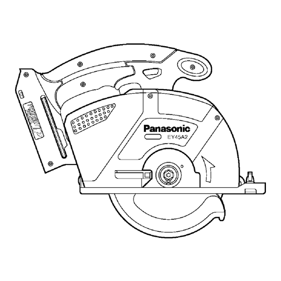
Panasonic EY45A2 Service Manual
Cordless multi purpose cutter
Hide thumbs
Also See for EY45A2:
- Operating instructions manual (176 pages) ,
- Operating instructions manual (164 pages)
Advertisement
TABLE OF CONTENTS
1 Warning -------------------------------------------------------------- 2
2 Specifications ----------------------------------------------------- 2
3 Troubleshooting Guide ----------------------------------------- 3
4 Disassembly and Assembly Instructions ---------------- 6
5 Wiring Connection Diagram ---------------------------------15
6 Schematic Diagram ---------------------------------------------15
7 Exploded View and Replacement Parts List -----------16
Cordless Multi Purpose Cutter
Model No.
Europe
Oceania
PAGE
© Panasonic Corporation 2014. All rights reserved.
Unauthorized copying and distribution is a violation
of law.
Order Number PTD1402X36CE
EY45A2
PAGE
Advertisement

Related Manuals for Panasonic EY45A2

Summary of Contents for Panasonic EY45A2
-
Page 1: Table Of Contents
4 Disassembly and Assembly Instructions ---------------- 6 5 Wiring Connection Diagram ---------------------------------15 6 Schematic Diagram ---------------------------------------------15 7 Exploded View and Replacement Parts List -----------16 © Panasonic Corporation 2014. All rights reserved. Unauthorized copying and distribution is a violation of law. -
Page 2: Warning
1 Warning Caution: • Pb free solder has a higher melting point that standard solder; Typically the melting point is 50 - 70°F (30 - 40°C) higher. Please use a soldering iron with temperature control and adjust it to 750 ± 20°F (400 ± 10°C). In case of using high temperature solder- ing iron, please be careful not to heat too long. -
Page 3: Troubleshooting Guide
3 Troubleshooting Guide 3.1. Troubleshooting Guide... - Page 5 3.2. Trial Operation (After Checking Troubleshooting Guide) 3.2.1. Assembly • Confirm if there is no gap between housing A and B by pinching lead wires. • There is no dust or deformation on battery terminals. • Confirm all screws are tightened firmly. •...
-
Page 6: Disassembly And Assembly Instructions
4 Disassembly and Assembly Instructions *To assemble the tool, start with 4-10 and proceed to 4-1 4.1. Removing the Blade 4.2. Removing the safety cover B, front cover assembly and transparent cover... - Page 7 4.3. Removing the safety cover and lower guard...
- Page 9 4.4. Removing the base...
- Page 10 4.5. Removing the housing B 4.6. Removing the interior components...
- Page 11 4.7. Removing the driving assembly from the motor 4.8. Removing the switch and LED light from, and reattaching them to, the module assembly...
- Page 12 4.9. Removing the mid gear assembly and thrust plates 4.10. Apply grease (SUNLIGHT No.2 )to the gear box A assembly, mid gear assembly, and thrust plates...
- Page 13 4.11. Wiring and Assembly Points...
-
Page 15: Wiring Connection Diagram
5 Wiring Connection Diagram 6 Schematic Diagram... -
Page 16: Exploded View And Replacement Parts List
7 Exploded View and Replacement Parts List 7.1. Exploded View... - Page 17 7.2. Replacement Prts List Safety Ref. No. Part No. Part Name & Description Quantity Remarks DUST CASE ASSEMBLY WEY45A2X3047 HEX WRENCH WEY3542K7867 FLANGE SOCKET WEY3530K6256 (M5*12) OUTER WASHER WEY3501K1176 INNER WASHER WEY3503L1166 TAPPING SCREW WEY4542L9257 (K2*10) TAPPING SCREW WEY45A2L9037 (3*20), (13PCS/PK) FRONT COVER WEY45A2X3107 SAFETY COVER B...
Need help?
Do you have a question about the EY45A2 and is the answer not in the manual?
Questions and answers